

Page 1

OWNER’S MANUAL
Tilting Self-Contained
Gas Steam Jacketed Kettles
MODELS:
• FT-20GL • FT-40GL • FT-60GL • FT-80GL • FT-100GL
An Employee Owned Company
35 Garvey Street ● Everett ● MA ● 02149-4403 Form No. S-1922A
Tel: (617) 387-4100 ● Fax: (617) 387-4456 (MA)
Toll Free: (866) 698-3188 ● Outside MA Fax: (800) 227-2659
Customer Service: custserv@mi.com ● Visit Us At: www.mi.com
●
02/08
Page 2

TABLE OF CONTENTS
INSTALLATION ...............................................................................1-2
OPERATION ...................................................................................3
MAINTENANCE ..............................................................................4
TROUBLE-SHOOTING ..................................................................5
ILLUSTRA
WIRING ...........................................................................................13-14
TED PARTS LIST ...........................................................5-12
i
Page 3

INSTALLATION
Uncrate carefully. Report any hidden freight damage to
the freight company immediately.
Set unit in place. Be certain to maintain the following
minimum clearances to combustible construction. Side
“0” inches, back “4” inches at ue box. Level the unit
using a spirit level in all directions on the top of the kettle (lid up). Adjust the bottom foot on each leg to over-
come an uneven oor. Be certain to leave adequate
clearances for cleaning, maintenance and service. If
unit is also equipped with an optional water ll valve
it too must be connected with a exible water supply
tube, quick disconnect and strain relief.
Appliance location should have an exhaust system
provided directly above the appliance to exhaust
combustion generated by the gas burner. For use on
noncombustible oors. Minimum clearance from combustible and noncombustible constructions, sides “0”
inches, back “4” inches at ue box.
Clearance must be adequate in aisle and at the side
and back. Adequate clearances for air openings into
combustion chamber must be provided, as well as for
serviceability. All units must be installed in such a man-
ner that the ow of combustion and ventilation are not
obstructed. Provisions for an adequate air supply must
also be provided. Do not obstruct the lower front or left
side of the unit, as combustive air enters through these
areas.
DESCRIPTION: The kettle has double-wall construction of 300 series stainless steel forming a steam jacket
around the lower 2/3 of the kettle. The jacket enclosure
contains factory sealed water and antifreeze. The kettle
exterior is fully insulated. The bottom of the kettle is a
hemispherical design for superior heat circulation. The
recessed control panel is located on the front right side
of the unit in full view of the operator. Standard controls
include direct immersion thermostat, water sight glass,
cooking light, pressure gauge and electronic ignition
with ignition indicator light. Safety features include low
water cutoff with indicator light, pressure switch, pressure relief valve and a 100% safety gas shut off valve.
The kettle pivots on trunnions connected to the gear
and control consoles. The worm and gear tilting mechanism allows the kettle to tilt forward to a full 90° for
complete draining. The tilt mechanism is self locking
for positive stop action. The consoles are drip proof,
stainless steel clad and are supported on all welded 1
5/8” (41mm) diameter stainless steel legs with anged
feet.
kettle is A.S.M.E. code stamped for operation to 50
PSI. Temperature range from 150° F to 285° F.
120 VAC, 1pH, 50/60 Hz
OPTIONAL AT EXTRA COST:
Spring assist cover, HSC
2” tangent draw off, FDOR-2
3” tangent draw off, FDOR-3
Tri-Basket assembly
Single pantry faucet with swing spout, SP-12
Double pantry faucet with swing spout, DP-12
Graduated measuring strip, MS-1
Perforated strainer
Solid disk strainer DOS-2
316 stainless steel liner for high acid content
SERVICE CONNECTIONS: GAS INSTALLATION TO
CONFORM TO LOCAL CODES OR IN THE ABSENCE OF
LOCAL CODES TO NATIONAL FUEL GAS’ CODE - ANSI
Z223.l.- LATEST EDITION IN CANADA INSTALLATION IN
ACCORDANCE WITH CAN/CGA-B149.1 OR 0.2 OR CUR-
RENT CODE
The appliance and it’s individual shut-off valve
1.
.
must be disconnected from the gas supply piping
system during any pressure testing of that system at .test pressures in excess of 1/2 PSI (0.1
kg/cm2).
The appliance must be isolated from’ the gas sup-
2.
ply piping system by closing it’s individual manual
shut-off valve during any pressure testing of the
gas supply piping system at test pressures equal
to or less than 1/2 PSI (0.1 kg/cm2).
ELECTRICAL GROUNDING MUST BE PROVIDED IN ACCORDANCE WITH LOCAL CODES, OR IN THE ABSENCE
OF LOCAL CODES, WITH THE NATIONAL ELECTRIC
CODE, ANSI/NFPA 70 - LATEST EDITION’ IN CANADA
INSTALLATION IN ACCORDANCE WITH C.S.A. C22.1 CANADIAN ELECTRIC CODE PART 1.
WARNING: ELECTRICAL GROUNDING INSTRUCTIONS
UNITS EQUIPPED WITH A THREE-PRONG (GROUNDING) PLUG FOR YOUR PROTECTION AGAINST SHOCK
HAZARD AND SHOULD BE PLUGGED DIRECTLY INTO A
PROPERLY GROUNDED THREE-PRONG RECEPTACLE.
DO NOT CUT OR REMOVE THE GROUNDING PRONG
FROM THIS PLUG. (120 VOLT UNITS ONLY).
Units with these electrical rating are factory equipped
with a transformer.. To connect supply wire remove
top right cover and route supply wires and ground wire
through the hole in the back of console with strain relief
tting supplied. Connect wires to terminal block and
ground lug. Replace cover.
OPERATION SHALL BE BY: Natural or L.P. gas utiliz-
ing a high efciency power burner system. The steam
Wiring diagram for unit is located in side panel of the
left hand console facing the front of the unit..
1
Page 4
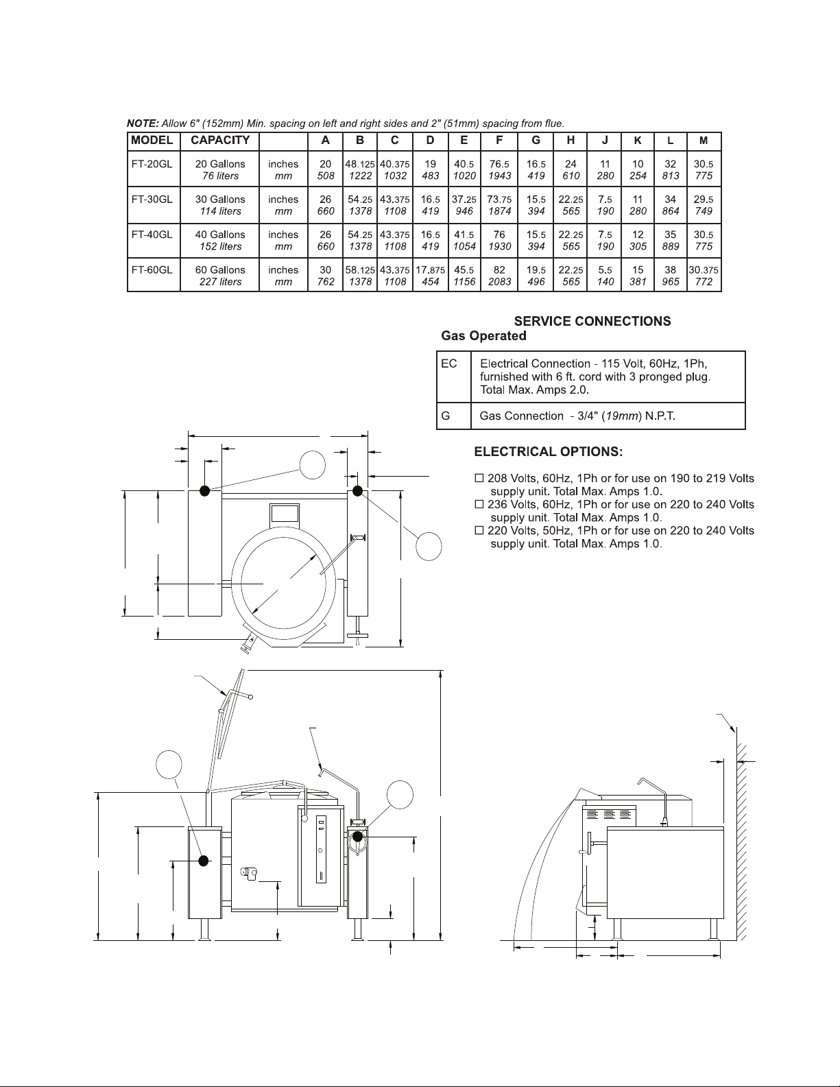
INSTALLATION
26�
660mm
35�
889mm
G
Optional Spring
Assist Cover
G
E
36 1/4�
921mm
H
D
EC
29�
736mm
6�
152mm
F
Optional Faucet
C
EC
6 1/4�
159mm
3 1/8�
79mm
10 1/4�
260mm
B
G
A
5 1/8�
130mm
Wall
4 Min.
102mm
J
K
M
L
Page 5

OPERATION
IMPORTANT NOTE: Unit is shipped with gas combi-
nation valve turned “ON”
OPEN MANUAL GAS SHUT OFF VALVE.
1.
WITH THERMOSTAT SET AT OFF.
2.
TURN POWER SWITCH ON.
3.
SET THERMOSTAT TO MAXIMUM, INITIATING
4.
A 30 SECOND PRE-PURGE.
NOTE: If after 36 seconds the burner fails to ig-
nite or burner lights then goes out the system goes
into safety lockout; de-energize the system by setting the thermostat to OFF for 5 minutes and try
again.
SET THERMOSTAT TO DESIRED TEMPERA-
5.
TURE SETTING.
DAILY SHUTDOWN
TURN POWER SWITCH OFF.
1.
TURN THERMOSTAT OFF.
2.
THERMOSTAT - The thermostat selects are de-
4.
sired internal kettle operating temperatures.
PRESSURE GAUGE - The pressure gauge indi-
5.
cates that internal operating pressure of the kettle. When cold, the gauge should indicate 25 to
30 inches mercury column vacuum. If it does not,
refer to “Re-establishing Vacuum” above this section. Under normal operation with the kettle empty
(thermostat set at 285oF) the pressure shall reach
38 PSI. When loaded the pressure may be considerably less.
SIGHT GLASS - The sight glass indicates the min-
6.
imum and maximum water level within the kettle.
If water level falls below minimum level more distilled water should be added. See “Adding Water”
section.
PRESSURE RELIEF VALVE - A safety device
7.
which prevents the internal kettle pressure from
ever exceeding 50 PSI. If should never be tampered with.
LOW WATER LIGHT COMES ON - ADD WATER
COMPLETE SHUTDOWN
TURN POWER SWITCH OFF.
1.
TURN THERMOSTAT OFF.
2.
TURN POWER SUPPLY TO UNIT OFF.
3.
REMOVE FRONT ACCESS PANEL ON LEFT
4.
SIDE AND TURN DIAL ON COMBINATION VALVE
TO OFF.
CLOSE MANUAL GAS SHUT OFF VALVE.
5.
FRONT PANEL CONTROLS
POWER SWITCH - This switch turns the main
1.
power to the unit on and off. If must be turned on to
heat the kettle. It should be turned of when kettle
will not be in use for long periods of time.
(RED) COOKING LIGHT - This light is on when-
2.
ever the main burner gas is on.
(AMBER) LOW WATER LIGHT - All kettles are
3.
supplied with sufcient distilled water in pressurized jacket. If at any time the water level falls be-
low that required for proper operation, the kettle
will not heat and this light will come on. See “Adding Water” Section.
Unit should be completely cold and off.
1.
Lift handle of pressure relief valve to release vac-
2.
uum in kettle.
Remove relief valve and attach a 3/4” NPT elbow
3.
pointing upward.
Using pure distilled water only, pour the water into
4.
the open end of the elbow (a funnel will be helpful).
Water will enter kettle slowly, as air must escape
through the same hole. Water should be added until water level is at the sight glass half way between
the minimum and maximum levels.
When sufcient water has been added, remove
5.
elbow and replace pressure relief for steam at 50
PSI.
Vacuum must be re-established.
6.
The total amount of distilled water in each kettle is:
FT-20GL - 6 Gallons of water
•
FT-30GL - 9 Gallons of water
•
FT-40GL - 9 Gallons of water
•
FT-60GL - 12 Gallons of water
•
3
Page 6

MAINTENANCE
PERIODIC MAINTENANCE
NOTICE: As a safety precaution, disconnect the power
supply during cleaning or servicing.
CLEANING
For easier cleaning add cold water to the kettle immediately after removing contents and let soak.
Wash exposed cleanable areas daily. To remove normal dirt, grease or product residue from stainless steel,
use ordinary soap and water applied with a sponge
or cloth. Dry thoroughly with a clean cloth. Never use
vinegar or any corrosion cleaner. Never, use ordinary
steel wool, wire brush or steel scouring pads. Never
use cleaning solvents with a hydrocarbon base on
control panel. Blower wheel inlet screen and motor air
vent should be cleansed if an accumulation of dust or
lint is obvious.
At least twice a year the unit venting system should be
examined and cleaned. At least twice a year have an
authorized Service Person clean and adjust the unit for
maximum performance.
RE-ESTABLISHING VACUUM
With the kettle completely cold a vacuum of 25 to 30
inches mercury column should be maintained as indicated by the pressure gauge on the front control
panel. If at any time the vacuum is less than 25 inches
M.C. the vacuum should be re-established. With the
kettle empty turn the thermostat knob to the highest
temperature. When the pressure gauge reaches 2.0
PSI turn thermostat off, open the pressure relief valve
until manometer reads 1 PSI then sharply release it.
This should remove the air and any loss in performance should return. Should the kettle fail to maintain
a vacuum after repeated attempts to establish it further
checks should be made to see if the pressure relief
valve is leaking or if there are any leaks in the pressure
relief valve piping, copper lines going to the pressure
switch, pressure gauge or thermostat tting.
ADJUSTMENTS
THERMOSTAT: The thermostat adjustment should not
be changed. Check the following before changing the
thermostat.
With kettle cold, the pressure on the pressure
1.
gauge should read 25 to 30 inches mercury column vacuum. If not, see “Re-establishing Vacuum”
above.
The pressure switch is .not set too high or too
2.
low and causing the out of adjustment condition.
A voltmeter should be used by a properly trained
servicemen to determine if the pressure switch or
thermostat is actually cycling the burners. If the
pressure switch is found to be the problem. See
“Pressure Switch” below.
PRESSURE SWITCH: The pressure switch should not
be adjusted until it is determined to be the cause of an
operating pressure difculty. See “thermostat” section
to determine if the source of difculty is the pressure
switch or thermostat, The major difculties caused by
pressure switch miss-adjustment are:
Pressure relief valve opening, especially on pre-
1.
heat from a cold start to 285oF (pressure switch
set too high).
Pressure in kettle is to low and burners are being
2.
shut down by pressure switch (not thermostat).
The pressure switch is preset for proper operation
from the factory. It is adjusted to the maximum pressure which will prevent the pressure relief valve from
opening. This setting will be slightly different on different kettles due to variations in the pressure relief
valves. During preheat to the maximum thermostat
setting (285oF), from either a cold condition or a lower
temperature setting, the temperature may overshoot
the thermostat setting and be shut down by the pressure switch. This is normal, however, after the kettle
has cycled several times (empty) the thermostat will
begin cycling the unit. .
TO ADJUST PRESSURE SWITCH:
With the kettle empty and completely cold, turn
1.
kettle on and set thermostat to maximum setting
(285oF).
Pressure in kettle (read pressure gauge on front
2.
panel) should reach a maximum pressure of 40
PSI and pressure relief valve should not open.
Kettle pressure may rise 3 or 4 PSI even afterburners shut down.
Relief valve should not open when kettle pressure
3.
is 40 PSI pressure switch setting is satisfactory.
If relief valve opens, reduce setting on pressure
4.
switch, cool kettle completely by running cold water through it and repeat this procedure.
If pressure in kettle is below 40 psi increase set-
5.
ting of pressure switch, cool kettle completely by
running cold water through it and repeat this procedure.
To obtain access to the pressure switch the front
6.
panel must be removed. Remove the screws on
either side of the panel. Be sure to support the
panel to avoid excessive strain on the wiring.
To increase the pressure switch setting turn the
7.
white ribbed knob clockwise; to decrease turn it
counterclockwise. Use the centre of the black ring
as an indicator.
4
Page 7

TROUBLE-SHOOTING
MOTOR WILL NOT RUN!
1. No Current.
2. Defective Thermostat.
3. Defective Motor.
4. Motor Overload Out.
5. Blown Fuse.
MOTOR RUNS, SPARK PRESENT
ON GAS IGNITION!
1. Manual Main Valve Off.
2. Miss-located Spark or Ground Rods.
3. Defective Valve.
4. Defective Primary Safety Control.
5. Air Shutter Open Too Far.
MOTOR RUNS, NO SPARK!
1. Defective Transformer.
2. Defective Spark Ignition.
3. Defective Spark Electrode (Cracked
Insulator).
4. Defective High Tension Wire.
5. Defective Centrifugal Switch on Motor.
FLAME BURNS ONLY ABOUT 6
SECONDS & SHUTS OFF!
1. Flame Rod or Flame Ground Misslocated.
2. Defective Flame Rod Wire.
3. Defective Primary Control.
NOTE: Loose, broken or grounded wiring may cause many of the
symptoms listed, Check all wiring make sure it is intact.
ILLUSTRATED PARTS
FIGURE 1.
ITEM PART NO. DESCRIPTION QTY.
1
2
3
4
5
6
7
8
9
10
11
12
13
*14
*
15
16
17
18
19
20
21
22
23
* SELECT AS REQUIRED.
97-5725 PILOT LIGHT - GREEN 24V 1
97-5423 INSTRUCTION LABEL 1
97-5424 L.W. MTG. BRACKET 1
97-5554 PROBE 1
97-5426 L.W. CUT OFF 1
97-5427 THERMOSTAT 1
97-5357 POLY PANEL 1
97-5429 POWER SWITCH 1
97-5430 PILOT LIGHT - RED 1
97-5431 PILOT LIGHT - AMBER 1
97-5559 DIAL 1
97-5433 PRESSURE GAUGE BRACKET 1
97-5002 PRESSURE GAUGE 1
97-5434 MTNG. BRKT (20, 30 & 40 GALLON ONLY) 1
97-3435 MTNG. BRKT (60 GALLON ONLY) 1
97-5436 SIHT GLASS 1
97-5437 PRESSURE SWITCH 1
97-5997 RELIEF VALVE 1
97-5032 FLANGE FOOT 4
10-6963 TERMINAL BLOCK 2
10-6962 END SECTION 1
97-5414 INTERLOCK SWITCH 1
97-5441 GROUND LUG 1
97-5415 VENT 1
5
SHORT FLAME!
1. Wrong Main Orice.
2. Low Gas Pressure.
3. Air Shutter Adjustment.
4. Main Manual Valve Partially Closed.
5. Inoperative Step Regulator Portion
of Main Valve.
LONG HAZY FLAME!
1. Wrong Main Orice.
2. High Gas Pressure.
3. Dirty Blower Wheel.
4. Air Shutter Adjustment.
5. Main Regulator Adjustment.
GAS FAILS TO SHUT OFF!
1. Dirt on Valve Seat.
2. Defective Main Valve.
Page 8

FIGURE 1.
ILLUSTRATED PARTS
6
Page 9

ILLUSTRATED PARTS
FIGURE 2.
ITEM PART NO. DESCRIPTION QTY.
10
11
12
1
2
3
4
5
6
7
8
9
97-5090 HANDWHEEL
97-5091 SET SCREW
97-5092 TILT SHAFT
97-5420 BUSHING
97-5094 WORM GEAR
97-5093 TENSION PIN
97-5095 THRUST BEARING
97-5096 JAM NUT
97-5845 KEY
97-5546 RETAINING RING
97-5416 SET SCREW
97-5098 SEGMENT GEAR
1
1
1
2
1
1
2
2
1
1
1
1
7
Page 10

FIGURE 3.
ILLUSTRATED PARTS
FIGURE 3.
ITEM PART NO. DESCRIPTION QTY.
**1
2
3
4
5
*
*
97-5829
98-6196
97-5902
97-5091
97-5090
97-5814
97-5832
CONSOLE COVER
CONSOLE COVER ASSY., FAUCET MOUNT (OPTIONAL)
SPACER, FAUCET MOUNT (OPTIONAL)
SET SCREW
HAND WHEEL
FRONT BEARING
TILT SHAFT
8
1
1
1
1
1
1
1
Page 11

ILLUSTRATED PARTS
FIGURE 3.
ITEM PART NO. DESCRIPTION QTY.
6
7
8
9
10
**11
12
13
14
15
16
17
18
19
20
21
22
23
24
25
26
27
28
29
**30
31
32
33
34
35
36
37
38
39
40
41
42
43
44
** NOT SHOWN.
** SELECT AS REQUIRED.
97-6494 TILT LABEL
97-5712 TRUNNION HOUSING ASSEMBLY
97-5845 KEY
97-5546 RETAINING RING
97-5737 ARM
97-5868 FLAT WASHER 3/8
97-5870 HEX SOCKET CAP SCREW, 3/8 -16 x 2- 1/8
97-5869 HEX SOCKET CAP SCREW, 3/8 -16x1- 1/4
97-5818 CHAIN LINK
97-5830 SCREW JACK
97-5735 BASE ASSEMBLY
97-5831 BASE BRACKET ASSEMBLY
97-5813 BEARING
97-5032 ADJUSTABLE FOOT
97-5732 SIDE PANEL
97-5738 TRUSS HEAD SLOT SCREW, 10-32 x 1/2
10-6963 TERMINAL BLOCK SECTION
10-6962 END SECTION
97-5848 EARTH ID TAG
97-5866 FLAT WASHER #10
97-5751 TRUSS HEAD PHILLIPS DRIVE, 10-32 x 1 1/4
97-5733 RD HEAD SLOT DRIVE SCREWS 8-32 x 1/4
97-5865 EXTERNAL TOOTH WASHER #8
97-5811 PIN
97-5872 HEX SOCKET SET SCREW 1/4 -20 x 1/2
97-5871 LOCK WASHER 3/8
97-5584 HEX NUT 3/8 - 16
97-5790 GREASE NIPPLE, 1/8 NPT
97-5652 FLAT WASHER 5/16
97-5739 HEX NUT 5/16 -18
97-5833 FLEXIBLE SHAFT GUIDE
97-5819 NYLON SHAFT GUIDE
97-5873 SET SCREW 1/4 -20 x 3/8
97-5741 EXTERNAL RETAINING RING
97-5815 KEY
97-6569 SPROCKET
97-5812 OUTPUT SHAFT
97-5816 SPROCKET
97-5817 CHAIN
1
1
1
1
1
**
1
8
1
1
1
1
2
2
1
10
2
1
1
2
2
3
3
1
1
**
7
1
2
2
1
2
1
1
2
1
1
1
1
9
Page 12

FIGURE 4.
ILLUSTRATED PARTS
FIGURE 4.
ITEM PART NO. DESCRIPTION QTY.
97-5530 HINGE ASSY - 20-40 GALLON KETTLE
10
1
2
3
4
5
6
6
7
8
9
97-5352 LOCK PIN
97-5343 END LOCK PLATE
97-5344 STATIONARY DISC
97-5698 CORES
97-5699 SPRING
97-5335 HANDLE ASSY- 20 GALLON KETTLE
97-5336 HANDLE ASSY - 30/40 GALLON KETTLE
97-5347 ROTARY DISC
97-5348 END STOP PLATE
97-5349 CAP SCREW
97-5337 KNOB
1
1
1
2
1
1
1
1
1
4
1
97-5464 HINGE ASSY - 60 GALLON KETTLE
10
1
2
3
4
5
6
7
8
9
97-5352 LOCK PIN
97-5343 END LOCK PLATE
97-5354 STATIONARY DISC
97-5345 CORES
97-5160 SPRING
97-5842 HANDLE ASSY
97-5352 ROTARY DISC
97-5356 END STOP PLATE
97-5545 CAP SCREWS
97-5337 KNOB
1
1
1
2
1
1
1
1
4
1
10
Page 13

ILLUSTRATED PARTS
FIGURE 5.
FIGURE 6.
FIGURE 6.
ITEM PART NO. DESCRIPTION QTY.
1.5”
VALVE
1
98-6155 98-6155 98-6155 NUT
2
3
4
5
6
7
-- -- -- HANDLE
97-5068 97-5069 97-5070 HEX ASSY NUT
97-5074 97-5072 97-5073 BONNET
97-5074 97-5074 97-5074 DISC & STEM ASSY
97-5077 97-5078 97-5079 O-RING
97-6496 97-6159 97-6497 VALVE BODY
2”
VALVE
3”
VALVE
1
1
1
1
1
1
1
11
Page 14

FIGURE 7.
ILLUSTRATED PARTS
12
Page 15

FIGURE 8.
WIRING
13
Page 16

FIGURE 9.
WIRING
14
Page 17

 Loading...