

Page 1

FT-GL & FT-GLF SERIES
2/3 AND FULLY JACKETED GAS TILTING KETTLES
PARTS AND SERVICE MANUAL
EFFECTIVE SEPTEMBER 16, 2014
The Company reserves the right to make substitution in the event that items specied are not available.
ERRORS: Descriptive and/or typographic errors are subject to correction.
44 Lakeside Avenue, Burlington, Vermont 05401 USA Telephone: (802) 658-6600 Fax: (802) 860-3732
Superseding All Previous Parts Lists.
MARKET FORGE INDUSTRIES
www.mi.com
P/N 14-0360 Rev A (9/14)
Page 2

TABLE OF CONTENTS
ADJUSTMENTS .......................................................................3
TROUBLESHOOTING ..................................................................6
ILLUSTRATED PART LIST
KETTLE ...............................................................................8
FT-20GL TILTING MECHANISM ....................................................... 10
TILT CONSOLE AND PARTS .......................................................... 12
INTERIOR COMPONENTS ........................................................... 15
SPRING ASSIST HINGE ASSEMBLY .................................................. 18
DRAW OFF VALVE ................................................................... 19
WIRING - 120V, 1 PHASE ............................................................ 21
WIRING - 220-240V, 1 PHASE ........................................................ 23
SEPTEMBER 16, 2014 2 FT-GL & FT-GLF SERIES GAS KETTLES
Page 3
ADJUSTMENTS
GENERAL
When any difculty arises always check that the unit has
been connected to the gas supply type and voltage for
which it was supplied. This can be done by examining
the serial plate on the lower right side of the unit. It will
list the gas type and voltage for which the unit was manu-
factured.
Wiring diagrams for the unit are located in a small enve-
lope afxed to the side panel of left hand console.
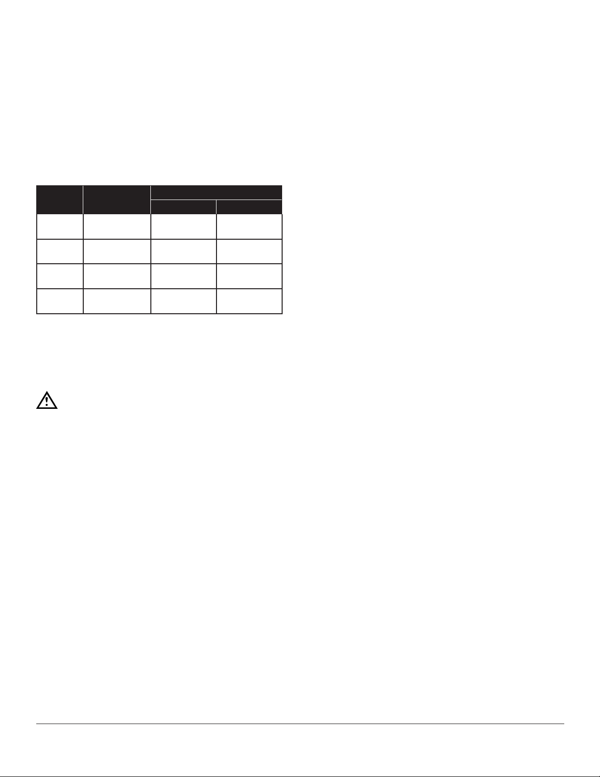
UNIT
FT-20GL
FT-30GL
FT-40GL
FT-60GL
TOTAL INPUT
BTU/HOUR
80,000
100,000
100,000
120,000
ORIFICE SIZE
Natural Propane
DMS # 19
(.166")
DMS # 13
(.185")
DMS # 13
(.185")
DMS # 7
(.201")
DMS # 30
(.125")
DMS # 27
(.144")
DMS # 27
(.144")
DMS # 23
(.154")
MANIFOLD PRESSURE
Natural Gas 3.5 inches W.C
LP Gas 4 inches W.C.
THERMOSTAT
The thermostat adjustment should not be changed.
Check the following before changing the thermostat.
1. With kettle cold, the pressure on the pressure gauge
should read in the green vacuum zone (25 to 30 inches Hg vacuum). If not, see ‘Re-establishing Vacuum”
section.
2. The pressure switch may be set too high or too low
and causing the out of adjustment condition. A voltmeter should be used by a properly trained service-
man to determine if the pressure switch or thermostat
is actually cycling the burners. If the pressure switch
is found to be cycling the burners, see “Pressure
Switch” section.
After verifying that the pressure switch is set and operat-
ing properly, the thermostat may be adjusted using the
set screw inside the stem. At maximum setting, the thermostat should cycle off at a gauge pressure reading of 30
psi. Turn set screw clockwise to decrease pressure and
counterclockwise to increase pressure.
ADJUSTMENTS
WARNING
Adjustments and service work may be per-
formed only by a qualied technician who is
experienced in, and knowledgeable with, the
operation of commercial gas cooking equip-
ment. To assure your condence, contact your
authorized service agency for reliable service,
dependable advice or other assistance, and
for genuine factory parts.
SEPTEMBER 16, 2014 3 FT-GL & FT-GLF SERIES GAS KETTLES
Page 4

ADJUSTMENTS
PRESSURE SWITCH
The pressure switch should not be adjusted until it is determined to be the cause of an operating pressure dif-
culty. See “Thermostat” section to determine if the source
of difculty is the pressure switch or thermostat.
The major difculties caused by pressure switch mis-ad-
justment are:
1. Pressure relief valve opening, pressure rises above
45 psi.
2. Pressure in kettle is less than 30 psi and burner is
being shut down by pressure switch (not thermostat).
The pressure switch is preset for proper operation from
the factory. It is adjusted to the maximum pressure which
will prevent the pressure relief valve from opening. Dur-
ing preheat to the maximum thermostat setting (275EF),
from either a cold condition or a lower temperature setting, the temperature may overshoot the thermostat set-
ting and be shut down by the pressure switch. This is
normal, however, after the kettle has cycled several times
(empty) the thermostat will begin cycling the unit.
TO ADJUST PRESSURE SWITCH:
1. To obtain access to the pressure switch, the front
panel must be removed. Remove the screws on bot-
tom of the panel. Be sure to support the panel to
avoid excessive strain on the wiring.
2. To increase the pressure switch setting, turn the white
ribbed knob clockwise; to decrease, turn it counterclockwise. Use the centre of the black ring as an in-
dicator.
3. With the kettle empty and completely cold, turn kettle
on and set thermostat to maximum setting (275EF).
4. The pressure in kettle (read pressure gauge on front
panel) should reach a maximum of 30 psi and pressure relief valve should not open. Kettle pressure
may rise 3 or 4 psi even after burners shut down.
5. Relief valve should not open when kettle pressure is
45 psi; pressure switch setting is satisfactory.
6. If the safety relief valve opens, reduce setting on
pressure switch, cool kettle completely by running
cold water through it and repeat steps 3 - 6.
7. If pressure in kettle is below 30 psi increase setting
of pressure switch, cool kettle completely by running
cold water through it and repeat steps 3 - 7.
ADDING WATER (Low water light comes on)
It may be necessary to replenish water in the jacket when
the low water indicator comes on. Do so as follows:
1. Unit should be completely cold and off.
2. Lift handle of pressure relief valve to release vacuum
in kettle. (Relief valve is at left rear of kettle.
3. Remove air vent nut on the elbow located at the rear
left of the unit.
4. Using pure distilled water only, pour the water into
the opening (a funnel will be helpful). Water will enter the kettle slowly, as air must escape through the
same hole. Water should be added until water level
at the sight glass is half way between the minimum
and maximum levels.
5. When sufcient water has been added, replace and
tighten the nut. Be sure to seal threads with a pipe
joint compound suitable for steam at 50 psi.
6. Vacuum must be re-established (See Re-establishing
Vacuum).
FOR REFERENCE:
The total amount of distilled water to be added when low
level pilot is illuminated:
FT-20GL 169 . oz. (5 L)
FT-30GL & FT-40GL 270 . oz. (8 L)
FT-60GL 372 . oz. (11 L)
RE-ESTABLISHING VACUUM
Periodically check pressure gauge when kettle is cold.
Reading should be in green vacuum zone (below 0 psi).
Otherwise air is present and proper heating will not occur. Use the following procedure to remove air and re-
establish vacuum:
With the kettle empty, turn the thermostat knob to the
highest temperature. When the temperature pilot light
goes off, open air vent nut one (1) full turn for 20 seconds
and then close and tighten the nut. This should remove
the air and any loss in performance should return.
Should the kettle fail to maintain a vacuum after repeated
attempts to establish vacuum, further checks should be
made to see if the pressure relief valve is leaking or if
there are any leaks in the pressure relief valve piping,
copper lines going to the pressure switch, pressure gauge
or thermostat tting.
8. Allow the kettle to cycle several times to verify the
correct pressure setting.
9. Replace the front panel when adjustment is complete.
SEPTEMBER 16, 2014 4 FT-GL & FT-GLF SERIES GAS KETTLES
Page 5

ADJUSTMENTS
SAFETY VALVE MAINTENANCE AND TESTING
CAUTION
Under normal operating conditions a “try lever
test” should be performed every two months.
Under severe service conditions, or if corro-
sion and/or deposits are noticed within the
valve body, testing must be performed more
often. A “try lever test” should also be performed at the end of any non-service period.
CAUTION
Hot, high pressure uid may be discharged
from body drain and vent during “try lever”
test. Care must be taken to avoid any bodily
contact.
CAUTION
High sound levels may be experienced during
“try lever” test. Wear proper safety equipment and exercise extreme care! Test at, or
near, half of the operating pressure by holding
the test lever fully open for at least two seconds to ush the valve seat free of sediment
and debris. Then release lever and permit the
valve to snap shut.
If lift lever does not activate, or there is no
evidence of discharge, turn off equipment im-
mediately and contact a licensed contractor or
qualied service personnel.
SEPTEMBER 16, 2014 5 FT-GL & FT-GLF SERIES GAS KETTLES
Page 6

TROUBLESHOOTING
PROBLEM LOOK FOR
Motor will not run.
Motor runs, no spark.
Motor runs, spark present, no gas ignition.
• No current. Check that power is being supplied to the unit.
• Defective thermostat or pressure switch.
• Defective motor.
• Motor overload out.
• Blown fuse.
• Defective transformer.
• Defective ignition module.
• Blown fuse on ignition module.
• Defective spark electrode (cracked insulator).
• Defective ignition cable.
• Defective centrifugal switch on motor.
• Manual main valve off.
• Mislocated spark or ground rods.
• Defective valve.
• Defective ignition module.
Low water light comes on.
Relief valve opens.
Flame burns only about 6 seconds and shuts off.
• Burner rate set too high. Ensure that manifold pressure is set per
rating plate and that correct orice size installed
• Burner getting too much air. Reduce air shutter opening (not below
1.0).
• Add water - See previous section ADJUSTMENTS.
• Pressure switch set too high.
• Pressure gauge is not accurate.
• Relief valve is faulty
• Flame rod or ame ground mislocated.
• Defective ame rod wire.
• Defective ignition module.
• Burner rate set too high. Ensure that manifold pressure is set per
rating plate and that correct orice size installed
• Burner getting too much air. Reduce air shutter opening (not below
1.0).
SEPTEMBER 16, 2014 6 FT-GL & FT-GLF SERIES GAS KETTLES
Page 7

TROUBLESHOOTING
PROBLEM LOOK FOR
Short ame.
Long hazy ame.
Gas fails to shut off.
NOTE: Loose, broken or grounded wiring may cause many of the symptoms listed. Check all wiring and make sure it is intact.
• Wrong size orice.
• Low gas pressure.
• Air shutter adjustment.
• Main manual valve partially closed.
• Wrong size orice.
• High gas pressure.
• Dirty blower wheel or intake.
• Air shutter adjustments.
• Dirt on valve seat.
• Defective main valve.
SEPTEMBER 16, 2014 7 FT-GL & FT-GLF SERIES GAS KETTLES
Page 8
KETTLE
SEPTEMBER 16, 2014 8 FT-GL & FT-GLF SERIES GAS KETTLES
Page 9

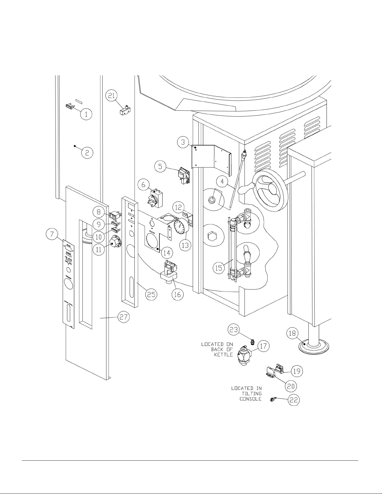
KETTLE
ITEM PART NO. DESCRIPTION QTY
1 97-5725 Pilot Light - Green 24V 1
2 97-5423 Instruction Label 1
3 97-5424 Low Water Control Mounting Bracket 1
**4 97-5554 Probe, 9 3/4” (20 Gallon) 1
97-5580 Probe, 9 1/4” (30, 40, 60 Gallon) 1
5 97-5426 Low Water Cut Off Control 1
6 97-5427 Thermostat 1
7 97-5357 Poly Panel 1
8 97-5429 Power Switch 1
9 97-5430 Pilot Light - Red 1
10 97-5431 Pilot Light - Amber 1
11 97-5559 Dial 1
12 97-5433 Pressure Gauge Bracket 1
13 97-5002 Pressure Gauge 1
**14 97-5434 Mounting Bracket (30, 40 Gallon Only) 1
97-3435 Mounting Bracket (20, 60 Gallon Only) 1
15 97-5436 Sight Glass Assembly 1
97-7254 Glass, 5/8" x 8" Long 1
97-7182 Rods 2
97-7180 Washer - Rubber 2
97-7181 Washer - Brass 2
16 97-5437 Pressure Switch 1
17 97-5997 Relief Valve 1
18 97-5032 Flanged Foot 2
19 10-6963 Terminal Block Section 2
20 10-6962 End Section 1
21 97-5414 Interlock Switch 1
22 97-5441 Ground Lug 1
23 97-415 Vent 1
**24* 97-5643 Combustion Chamber (FT-20GL) 1
97-5644 Combustion Chamber (FT-30GL & FT-40GL) 1
97-5645 Combustion Chamber (FT-60GL & FT-40GLF) 1
25 97-7174 Recessed Control Panel 1
**26* 97-7262 Bottom Cover (FT-20GL) 1
97-7263 Bottom Cover (FT-30GL & FT-40GL) 1
97-7264 Bottom Cover (FT-60GL & FT-40GLF) 1
**27 97-7265 Control Panel (FT-20GL) 1
97-7266 Control Panel (FT-30GL) 1
97-7267 Control Panel (FT-40GL) 1
97-7268 Control Panel (FT-60GLF) 1
97-7269 Control Panel (FT-40GLF) 1
* NOT SHOWN.
** SELECT AS REQUIRED.
SEPTEMBER 16, 2014 9 FT-GL & FT-GLF SERIES GAS KETTLES
Page 10

FT-20GL TILTING MECHANISM
SEPTEMBER 16, 2014 10 FT-GL & FT-GLF SERIES GAS KETTLES
Page 11

FT-20GL TILTING MECHANISM
ITEM PART NO. DESCRIPTION QTY
1 97-5090 Handwheel 1
2 97-5091 Set Screw 1
3 97-5092 Tilt Shaft 1
4 97-5420 Bushing 2
5 97-5094 Worm Gear (Includes Items 6 - 12) 1
97-5098 Segment Gear (Includes Items 6 - 12) 1
6 97-5093 Tension Pin, 3/16" D x 1-1/4" L 1
7 97-5845 Key 1
8 97-5546 Retaining Ring 1
9 97-5416 Set Screw 2
10 97-7246 Bolt 1
11 97-7247 Washer, Flat, 1/2" 1
12 97-7248 Nut, 1/2-13UNC 1
13 97-5820 Washer 3/4 ID x 1 - 1/4 OD 1
14. 97-5821 Cotter Pin S.S. 3/16 x 1 1
*15 97-5702 Cord Set, 120V 1
*16 97-6494 Decal – Tilt 1
17 97-5095 Thrust Bearing 2
18 97-5096 Jam Nut 2
*19 97-7249 Console Cover 1
*20 97-5720 Console Cover Assembly (Faucet Mount), Optional 1
*21 97-5902 Spacer (Faucet Mount) 1
* NOT SHOWN.
SEPTEMBER 16, 2014 11 FT-GL & FT-GLF SERIES GAS KETTLES
Page 12

TILT CONSOLE AND PARTS
SEPTEMBER 16, 2014 12 FT-GL & FT-GLF SERIES GAS KETTLES
Page 13

TILT CONSOLE AND PARTS
ITEM PART NO. DESCRIPTION QTY
**1 97-5829 Console Cover 1
* 98-6196 Console Cover Assembly (Faucet Mount), OPTIONAL. 1
* 97-5902 Spacer (Faucet Mount), OPTIONAL. 1
2 97-5091 Set Screw 1
3 97-5090 Handwheel 1
4 97-5814 Front Bearing 1
5 97-5832 Tilt Shaft 1
6 97-6494 Tilt Label 1
7 97-5712 Trunnion Housing Assembly 1
8 97-5845 Key 1
9 97-5546 Retaining Ring 1
10 97-5737 Arm 1
11 97-5868 Flat Washer 3/8 As Required
12 97-5870 Hex Socket Cap Screw, 3/8 - 16 x 2 - 1/8 1
13 97-5869 Hex Socket Cap Screw, 3/8 - 16 x 1 - 1/4 8
14 97-5818 Chain Link 1
15 97-5830 Screw Jack 1
97-5830 Screw Jack, FT-40GLF 1
16 97-5735 Base Assembly 1
97-7251 Base Assembly, FT-40GLF 1
17 97-5831 Base Bracket Assembly 1
18 97-5813 Bearing 2
19 97-5032 Adjustable Foot 2
20 97-5732 Side Panel 1
21 97-5738 Truss HD Slot Screw, 10 - 32 x 1/2 10
22 10-6963 Terminal Block Section 2
23 10-6962 End Section 1
24 97-5848 Earth ID Tag 1
25 97-5866 Flat Washer #10 2
26 97-5751 Truss HD Phillips Drive, 10 - 32 x 1-1/4 2
27 97-5733 RD HD Slot Drive Screws, 8 - 32 x 1/4 3
28 97-5865 External Tooth Washer # 8 3
29 97-5811 Pin, Rod End of Screw Jack 1
30 97-7252 Retaining Ring, External, 18 mm 2
31 97-5871 Lock Washer, 3/8 As Required
32 97-5584 Hex Nut, 3/8 - 16 7
33 97-5790 Grease Nipple, 1/8 NPT 1
34 97-5652 Flat Washer, 5/16 2
SEPTEMBER 16, 2014 13 FT-GL & FT-GLF SERIES GAS KETTLES
Page 14

TILT CONSOLE AND PARTS
ITEM PART NO. DESCRIPTION QTY
35 97-5739 Hex Nut, 5/16 - 18 2
36 97-5833 Flexible Shaft Assembly 1
37 97-5819 Nylon Shaft Guide 2
38 97-5873 Set Screw, 1/4 - 28 x 3/8 1
39 97-5741 External Retaining Ring 1
40 97-5815 Key 2
41 97-6569 Sprocket 1
42 97-5812 Output Shaft 1
43 97-5816 Sprocket 1
44 97-5817 Chain 1
*45 97-7275 Single Faucet, 18", OPTIONAL 1
97-7276 Double Faucet, 18", OPTIONAL 1
46 97-7277 Bushing, DU, 18d x 20D c 15L 4
* NOT SHOWN.
** SELECT AS REQUIRED.
SEPTEMBER 16, 2014 14 FT-GL & FT-GLF SERIES GAS KETTLES
Page 15

INTERIOR COMPONENTS
SEPTEMBER 16, 2014 15 FT-GL & FT-GLF SERIES GAS KETTLES
Page 16

INTERIOR COMPONENTS
ITEM PART NO. DESCRIPTION
**1 97-7278 Complete Burner Assembly, Natural Gas 1
97-7279 Complete Burner Assembly, LP Gas 1
97-7280 Complete Burner Assembly, Natural Gas 1
97-7281 Complete Burner Assembly, LP Gas 1
97-7282 Complete Burner Assembly, Natural Gas 1
97-7283 Complete Burner Assembly, LP Gas 1
97-7282 Complete Burner Assembly, Natural Gas, FT-40GLF 1
97-7283 Complete Burner Assembly, LP Gas, FT-40GLF 1
2 97-5311 DSI Module 1 1 1
3 97-7284 Ignition Wire, 18" 1 1 1
4 97-5476 Fuse, 250V, 3 Amp. 1 1 1
5 97-5313 Transformer, 120/24V, 50/60, 30 VA 1 1 1
6 97-7272 Motor/Blower, 115V/50/60 Hz 1 1 1
7 97-7286 Control/Ignition Module Wire Harness 1 1 1
8 97-7287 Air Shutter Assembly 1 1 1
9 97-7288 Venturi Assembly 1 1 1
10 97-6400 Electrode Assembly 1 1 1
11 97-7289 Electrode Mounting Bracket 1 1 1
12 97-7290 Adaptor Bushing, 7/8" 1 1 1
13 97-7291 Control Box with Strap 1 1 1
14 97-7292 Control Box Lid 1 1 1
15 97-7293 Tube/Housing, 6" 1 1 1
16 97-7294 Flange Gasket, 6-1/2" Square 1 1 1
17 97-7295 Adjustable Flange Assembly, 6-1/2" Square 1 1 1
18 97-7296 Gas Valve (Natural/L.P.), 3/4" x 3/4" 1 1 1
**19 97-6947 Orice #19, Natural Gas 1
97-7297 Orice #30, L.P. Gas 1
97-7298 Orice #13, Natural Gas 1
97-6378 Orice #27, L.P. Gas 1
97-7299 Orice #7, Natural Gas, 60 & 40GLF 1 1
97-6383 Orice #23, L.P. Gas, 60 & 40GLF 1 1
20 97-7300 Orice Holder 1 1 1
21 97-6252 Gas Flex Tube 1 1 1
22 97-5414 Interlock Switch, Tilt Switch 1 1 1
97-7301 Interlock Switch, Tilt Switch, 40GLF 1
23 97-5712 Trunnion Housing Assembly 1 1 1
**24* 97-7302 Console Cover, Kettles without Covers 1 1 1
97-7303 Console Cover, Kettles with Covers 1 1 1
QTY.
20 GAL.
QTY.
30/40 GAL.
QTY.
60 GAL.
SEPTEMBER 16, 2014 16 FT-GL & FT-GLF SERIES GAS KETTLES
Page 17

INTERIOR COMPONENTS
ITEM PART NO. DESCRIPTION
25 97-7304 Console Nozzle Assembly 1 1 1
26 97-7305 Nozzle Cover 1 1 1
27 97-7306 Gas Supply Pipe Assembly 1 1 1
28 97-6287 Reducer Bushing, 1/2 x 3/4 1 1 1
97-7307 Hex Bushing, 1/2 x ¾, FT-40GLF 1
*29 97-5358
**30* 97-6187 Fuse Holder (220-240V, 50 Hz Units) 1 1 1
97-6187 Fuse Holder (240V, 60 Hz Units) 2 2 2
**31* 97-7274 Fuse, 2A, 600V (220-240V, 50 Hz Units) 1 1 1
97-7274 Fuse, 2A, 600V (240V, 60 Hz Units) 2 2 2
* NOT SHOWN.
** SELECT AS REQUIRED.
Transformer , 220-240/120V, 200VA 50/60 Hz, (Units rated 220240V only)
QTY.
20 GAL.
1 1 1
QTY.
30/40 GAL.
QTY.
60 GAL.
SEPTEMBER 16, 2014 17 FT-GL & FT-GLF SERIES GAS KETTLES
Page 18

SPRING ASSIST HINGE ASSEMBLY
ITEM PART NO. DESCRIPTION QTY
97-5530 HINGE ASSEMBLY -20-40 1
97-5464 HINGE ASSEMBLY- 60 1
1 97-5352 Lock Pin 1
2 97-5343 End Lock Plate 1
3 97-5344 Stationary Disc 1
4 97-5698 Core 1
5 97-5699 Spring 1
**6 97-5335 Handle Assembly (FT-20GL) 1
97-5336 Handle Assembly (FT-30GL & FT-40GL) 1
97-5842 Handle Assembly (FT-6GL) 1
97-7270 Handle Assembly (FT-40GLF) 1
7 97-5347 Rotary Disc 1
8 97-5348 End Stop Plate 1
9 97-5349 Cap Screws, 1/4-20 X 3/4 4
10 97-5337 Knob 1
**11 97-6393 Hinge Support Riser (20, 30, 40 Gallon) 1
97-7271 Hinge Support Riser (60 Gallon) 1
**12 97-5742 Cover, 20 Gallon Kettle 1
97-5053 Cover, 30, 40 Gallon Kettle 1
97-5054 Cover, 60 Gallon Kettle 1
** SELECT AS REQUIRED.
SEPTEMBER 16, 2014 18 FT-GL & FT-GLF SERIES GAS KETTLES
Page 19

DRAW OFF VALVE
1-1/2” DRAW-OFF VALVE ASSEMBLY
ITEM PART NO. DESCRIPTION QTY
97-5062 1-1/2” DRAW-OFF VALVE ASSEMBLY
1 98-6155 Acorn Nut 10-24 UNC 1
2 97-5566 Handle, Stainless Steel 1
3 97-5068 Gland Nut 1
4 97-5074 Bonnet 1
5 97-5077 “O” Ring 1
6 97-5074 Stem Assembly 1
7 97-6496 Valve Body 1
SEPTEMBER 16, 2014 19 FT-GL & FT-GLF SERIES GAS KETTLES
Page 20

DRAW OFF VALVE
2” DRAW-OFF VALVE ASSEMBLY
ITEM PART NO. DESCRIPTION QTY
97-5063 2" DRAW-OFF VALVE ASSEMBLY
1 98-6155 Acorn Nut 10-24 UNC 1
2 97-5566 Handle, Stainless Steel 1
3 97-5069 Gland Nut 1
4 97-5072 Bonnet 1
5 97-5078 “O” Ring 1
6 97-5074 Stem Assembly 1
7 97-6159 Valve Body 1
3” DRAW-OFF VALVE ASSEMBLY
ITEM PART NO. DESCRIPTION QTY
97-5605 3" DRAW-OFF VALVE ASSEMBLY
1 98-6155 Acorn Nut, 7/16 - 14 UNC 1
2 97-5067 Handle, Stainless Steel 1
3 97-5070 Gland Nut 1
4 97-5073 Bonnet 1
5 97-5079 “O” Ring 1
6 97-5074 Stem Assembly 1
7 97-6497 Valve Body 1
SEPTEMBER 16, 2014 20 FT-GL & FT-GLF SERIES GAS KETTLES
Page 21

WIRING - 120V, 1 PHASE
SEPTEMBER 16, 2014 21 FT-GL & FT-GLF SERIES GAS KETTLES
Page 22

WIRING - 120V, 1 PHASE
ITEM PART NO. DESCRIPTION QTY
1 10-6962 TERMINAL BLOCK END SECTION 1
2 10-6963 TERMINAL BLOCK SECTION 2
3 97-5429 POWER SWITCH 1
4 97-6656 LEVEL CONTROL 1
5 97-5710 PILOT LIGHT, LOW WATER, AMBER 1
6 97-5709 PILOT LIGHT, COOKING, RED 1
7 97-5437 PRESSURE SWITCH 1
8 97-5427 THERMOSTAT 1
9 97-5313 TRANSFORMER, 120/24 30VA 1
10 97-7272 BLOWER MOTOR WITH INTERLOCK 1
11 97-5475 FUSE, 3 AMP, 250V BUSS 1
12 97-7208 GAS COMBINATION VALVE 1
13 97-5311 DSI MODULE 1
14 -- ELECTRODE ASSEMBLY 1
15 97-5422 PILOT LIGHT, IGNITION 1
16 97-5554 LEVEL PROBE 1
17 97-5414 TILT SWITCH 1
SEPTEMBER 16, 2014 22 FT-GL & FT-GLF SERIES GAS KETTLES
Page 23

WIRING - 220-240V, 1 PHASE
SEPTEMBER 16, 2014 23 FT-GL & FT-GLF SERIES GAS KETTLES
Page 24

WIRING - 120V, 1 PHASE
ITEM PART NO. DESCRIPTION QTY
1 10-6962 TERMINAL BLOCK END SECTION 1
2 10-6963 TERMINAL BLOCK SECTION 2
3 97-5429 POWER SWITCH 1
4 97-5565 LEVEL CONTROL 1
5 97-5710 PILOT LIGHT, LOW WATER, AMBER 1
6 97-5709 PILOT LIGHT, COOKING, RED 1
7 97-5437 PRESSURE SWITCH 1
8 97-5427 THERMOSTAT 1
9 97-5313 TRANSFORMER, 120/24 30VA 1
10 97-7272 BLOWER MOTOR WITH INTERLOCK 1
11 97-5475 FUSE, 3 AMP, 250V BUSS 1
12 97-7208 GAS COMBINATION VALVE 1
13 97-5311 DSI MODULE 1
14 -- ELECTRODE ASSEMBLY 1
15 97-5422 PILOT LIGHT, IGNITION 1
16 97-5554 LEVEL PROBE 1
17 97-5414 TILT SWITCH 1
18 97-7274 FUSE, 2 AMP. 600V 1*
19 97-5359 FUSE HOLDER 1*
20 97-5358 TRANSFORMER, 240/120 200VA 1
* FOR 240V-60Hz USE 2 FUSES AND 2 FUSE HOLDERS.
SEPTEMBER 16, 2014 24 FT-GL & FT-GLF SERIES GAS KETTLES
 Loading...