

Page 1
OWNER’S MANUAL
Self-Contained Electric Steam Jacketed Kettles
MODELS: FCT-4CE
FCT-6CE
FCT-10CE
FCT-12CE
An Employee Owned Company
35 Garvey Street ● Everett ● MA ● 02149-4403 Form No. S-4348B
Tel: (617) 387-4100 ● Fax: (617) 387-4456 (MA)
Toll Free: (866) 698-3188 ● Outside MA Fax: (800) 227-2659
Customer Service: custserv@mi.com ● Visit Us At: www.mi.com
●
07/07
Page 2

TABLE OF CONTENTS
INSTALLATION ...............................................................................1-2
OPERATION ................................................................................... 3
MAINTENANCE ..............................................................................
ILLUSTRATED PARTS LIST ...........................................................5-9
4
i
Page 3
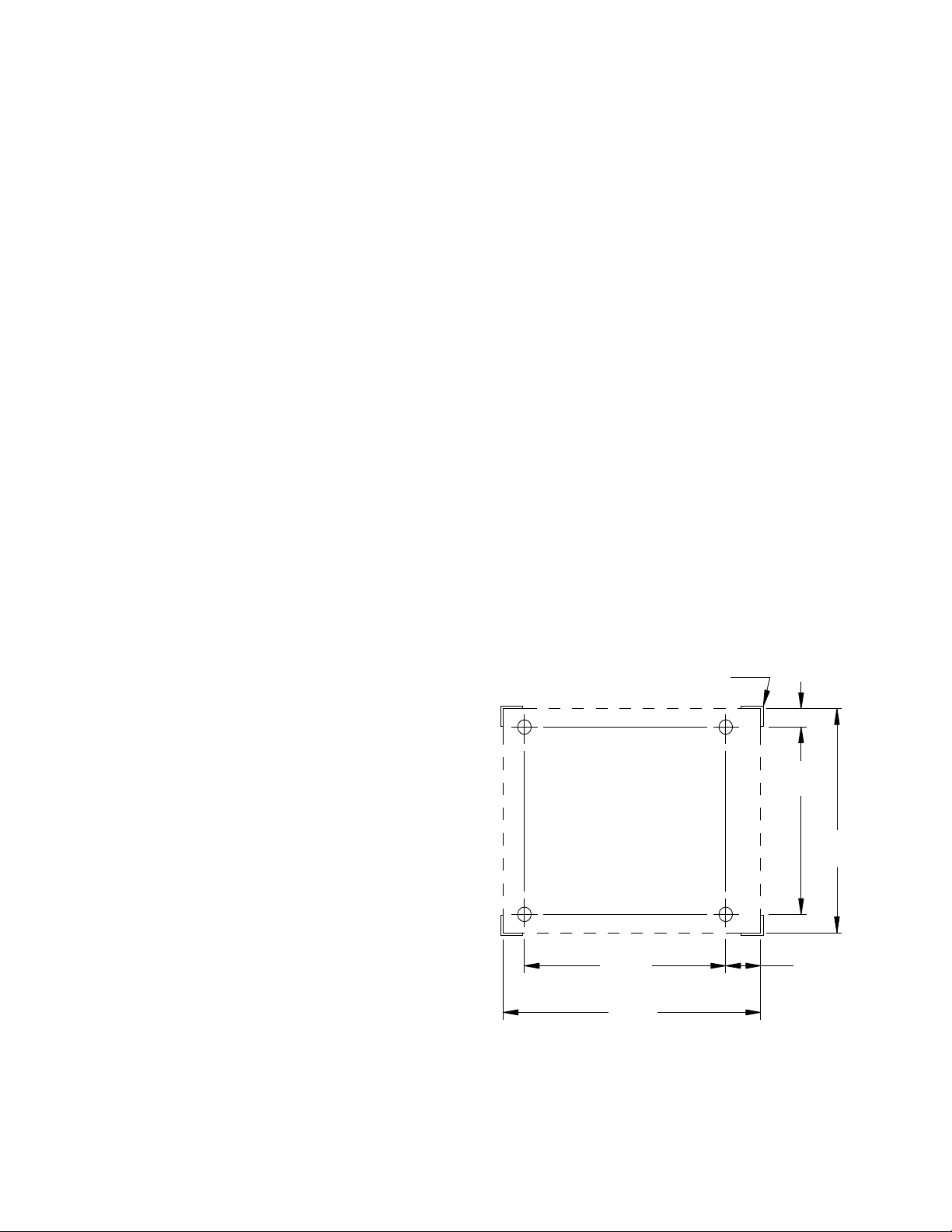
INSTALLATION
18"
457mm
1 1"/4
32mm
14 1/2"
368mm
2 1/4"
57mm
10"
254mm
12 1/2"
317mm
MARK (4) CORNERS
ON COUNTER
INSTALLATION ON COUNTER SURFACE:
Position kettle on counter allowing sufcient rear
1.
clearance from wall to tilt freely and completely
without obstruction.
Mark (4) corner locations of kettle base, as shown
2.
in Figure 1.
Remove kettle from counter and locate position of
3.
4 holes as per above drawing. Drill four 7/6” diameter holes.
Apply a continuous bead of Silastic or other equiv-
4.
alent sealant along the complete perimeter edge
of the kettle base.
Use 5/16 - 18 x 1 1/2” Hex Cap Screws with suit-
5.
able at washers to bolt down.
Wipe off excess sealant.
6.
A Control Box with power supply equivalent to
7.
Electrical Rating of kettle should be located conveniently nearby.
A waterproof electrical connection for power sup-
8.
ply to console housing must be provided.
Ground kettle to terminal provided inside console
9.
housing.
Turn power ON and check for proper operation.
10.
MODELS: FCT- 4CE FCT- 6CE
FCT-10CE FCT-12CE
Water Tight Controls will be integrally mounted to the
kettle and control console and includes an on-off switch,
solid state temperature controller with pilot light, low
water shut off light, pressure/vacuum gauge, pressure
safety valve, and air bleed vent. Kettle will operate in
a temperature range of approximately 100o to 298oF
(38o-148oC) at a pressure not to exceed 50 PSI (3.5 kg/
cm2). Mounting base will include kettle mounting lugs
concealed inside a rectangular enclosure.
OPERATION SHALL BE BY: *Optional at extra cost.
Electrically, self-generating closed steam system
equipped for operation on:
208 VAC, 1 Phase or 3 Phase, 50/60 Hz.
240 VAC, 1 Phase or 3 Phase, 50/60 Hz.
*480 VAC, 3 Phase, 50/60 Hz.
220/380 VAC, 3 Phase 4 wire 50Hz.
240/415 VAC, 3 Phase 4 wire 50Hz.
OPTIONAL AT EXTRA COST:
One piece lift off stainless steel cover.
Stainless steel wire basket.
Low, Open, Stainless Steel Stand.
(30’’ Wide x 20’’ High)
Vegetable Strainer.
30” Lowboy Stainless Steel Stand with Sink
Drain. (4, 6, 10 and 12 Gallon Only)
Figure 1.
DESCRIPTION: Will be a Market Forged self-generating, countertop tilting kettle, with hand crank.
FCT-4CE 4 Gallon 16 Liter Capacity
FCT-6CE 6 Gallon 23 Liter Capacity
FCT-10CE 10 Gallon 38 Liter Capacity
FCT-12CE 12 Gallon 45 Liter Capacity
Kettle will be constructed of welded satin nish, type
316, stainless steel. The kettle will be jacketed by an
outer kettle, which encloses heating element, water
and anti-freeze required to generate steam. Heating
element can be easily removed for service and will
automatically shut off when kettle is tilted to prevent
element damage. Kettle will be equipped with crank
handle with positive stop.
1
Page 4
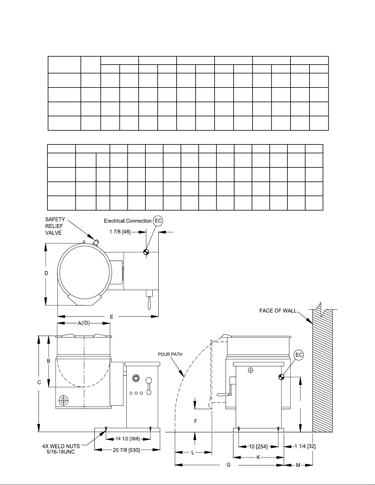
INSTALLATION
J
ELECTRICAL CHARACTERISTICS
MODEL pH
FCT-4CE
FCT-6CE
FCT-10CE
FCT-12CE
MODEL CAPACITY A B C D E F G H J K L M
FCT-4CE 4 Gal.
FCT-6CE 6 Gal.
FCT-10CE 10 Gal.
FCT-12CE 12 Gal.
1
3
1
3
1
3
1
3
16 Liters
23 Liters
38 Liters
45 Liters
208V 230V 240V 380V 415V 480V
kW Amp kW Amp kW Amp kW Amp kW Amp kW Amp
7.5
7.53620.8
7.5
7.53620.8
121257.6
33.31212
121257.6
33.31212
inmm12
305
inmm12
30514356256381538725638410228711
inmm16
40615381
inmm16
40617432
7.5
7.5
7.5
7.5
-- --
25.5
64819486
27.5
69919486
32.6
18.8
32.6
18.8
52.2
30.212125028.9 12 18.3 12 16.7 12 14.5
52.2
30.212125028.9 12 18.3 12 16.7 12 14.5
7.5
31.3
7.5
18.1 7.5 11.4 7.5 10.4 7.5 9
7.5
31.3
7.5
18.1 7.5 11.4 7.5 10.4 7.5 9
CAPACITY
15
38725638410228711
28 7/8
734410228711
28 7/8
734410230762
6 1/8
15613330
6 1/8
15613330
6 1/8
15613330
6 1/8
15613330
12 3/4
32410254
12 3/4
32410254
12 3/4
12 3/4
324
12 3/4
12 3/4
324
324
324
6 1/8
156
6 1/8
156
6 1/8
156
6 1/8
156
Figure 2.
Page 5

OPERATION
5
4
3
2
1
6
COOKING:
Ensure that the external electrical shut-off to kettle is on.
1.
Check pressure gauge for correct cold kettle reading. Reading should be 25-30 In.Hg of vacuum. If reading
2.
is not low enough, follow VENTING procedure prior to using kettle.
Place power switch in ON position.
3.
Preheat kettle by placing thermostat knob at ‘10’ and wait until TEMPERATURE light goes off.
4.
NOTE: Preheating should not be used when cooking milk and egg food products which adhere to hot cooking surfaces. These foods should be placed into kettle before heating is begun.
Add food to be cooked into kettle.
5.
Place thermostat knob at required temperature setting from ‘1’ to ‘10’ coinciding with a temperature range
6.
from roughly 90°F to 300°F (32°C to 149°C) in the reservoir. Approximate cooking temperatures with water
at various thermostat settings are as follows:
THERMOSTAT
SETTING
°F °C
4 90° 32°
5 125° 52°
6 160° 71°
7 195° 91°
8 231° 110°
9 273° 134°
10 300° 149°
APPROXIMATE TEMPERATURE
(WATER)
When cooking is nished, set thermostat knob and power switch to OFF position.
7.
Pour nished product from kettle using tilt handle. Be careful to avoid splashing.
8.
Add water to kettle for cleaning purposes.
9.
Wash kettle thoroughly. See CLEANING procedure.
10.
1. Hand Crank
2. Power Switch
3. Low Water Indicator Light
4. Temperature (Heat Indicator) Light
5. Temperature Control Thermostat
6. Vacuum/Pressure Gauge
Figure 3.
3
Page 6

MAINTENANCE
CLEANING:
The kettle interior and exterior should be thoroughly washed after each use in preparation of a different food.
Add water and mild detergent to the kettle immediately after use.
1.
Scrub kettle interior with a nylon brush.
2.
NOTE: Never scrape the inside of kettle with metal tools, steel scouring pads, or abrasive cleaners. Scratch-
es will result which will spoil the kettle’s general appearance and make it harder to clean and maintain in a
sanitary condition.
Loosen food which is stuck to kettle by allowing it to soak at a low temperature setting.
3.
Rinse with clear water and dry.
4.
WARNING: Do not hose down unit under any condition. Failure to comply will void warranty.
Wipe down exterior, rinse and dry.
5.
VENTING:
Check vacuum/pressure gauge when kettle is cold. Gauge should be in the vacuum zone between 25-30 In. Hg.
If not, air is present which must be vented (removed) for proper heating. Use the following procedures to vent
air.
Place power switch in ON position; kettle empty.
1.
Set temperature control thermostat to ‘10’. Heat kettle until heat indicator light goes off.
2.
Using a 7/16” wrench, open bleed vent one full turn for 10 seconds and close.
3.
Cool kettle. Check for proper vacuum of 25-30 In. Hg. If reading is not low enough, repeat entire procedure,
4.
steps 1-3.
FILLING-JACKET RESERVOIR:
The reservoir water level must be maintained at or above the minimum needed to submerge the heating elements. If the low water light turns on during use, the water level is not adequate and the low water protection
control has automatically shut off the heating elements. CAUTION: Before adding water to the reservoir, water
supply should be analyzed to ensure that hardness is no greater than 2.0- grains per gallon and pH level is within
the range of 7.0-8.5. Water which fails to meet these standards should be treated, or ionized distilled water with
sodium used. EQUIPMENT FAILURE CAUSED BY INADEQUATE WATER QUALITY IS NOT COVERED UNDER WARRANTY.
Use the following procedure to ll reservoir. Check vacuum/pressure gauge to ensure that there is no pressure
in kettle when adding water.
Turn thermostat and power switch to OFF position.
1.
Remove 7/16” vent tting from bleed vent on back of kettle. Insert a funnel into vent opening and add pre-
2.
scribed volume of water. For 6 gallon models, add 50 ounces (1.5 liters). For 10 and 12 gallon models, add
100 ounces (3 liters).
Replace and tighten vent tting.
3.
With kettle in upright position, the low water light should be off at this time. If so, follow venting procedure to
4.
vent air from reservoir Venting. If low water light is not off, repeat Filling Jacket Reservoir.
1. Bleed Vent
2. Pressure Relief Valve
Figure 4.
4
Page 7

Figure 5.
ILLUSTRATED PARTS
ITEM PART NO. DESCRIPTION
1 97-5004 Cover, Kettle Enclosure FCT-6CE
97-5006 Cover, Kettle, Enclosure FCT-10CE & -12CE
2 97-5005 Bolt, Enclosure Cover
3 97-5010 Air Vent 7/16”, Assy.
4 97-5009 Valve, Relief, Safely (50 PSI)
5 97.5007 Handle, Tilt, FCT-6CE, -10CE & -12CE
6 97-5008 Knob, Handle, Tilt
7 97-5011 Switch, Power
8 97-5026 Collar, Retaining
9 08-6362 Switch, Interlock
10 97-5144 Cover, Access, Element
11 97-5003 Cover, Box, Control
12 10-7934 Liquid Level Control
13 20-0043 Contactor
14 10-5069 Section, Terminal Block
5
Page 8

ILLUSTRATED PARTS
10-5070 End, Terminal Block
15 97-5024 Gasket FCT-6CE, Element
97-5025 Gasket FCT-10CE & -12CE, Element
16 10-7935 Probe
17 10-3425 Connector 1/4 x 1/4
18 97-5145 Tube, Copper, FCT-6CE
19 97-5146 Tube, Copper, FCT-10CE & -12CE
20 97-5002 Gauge, Pressure
21 97-5147 Plate, Mounting
22 10-6307 Knob Thermostat
23 09-6493 Controller, Temperature (thermostat)
24 97-0572 Potentiometer, Remote
25 09-6474 Sensor, temperature
26 20-0007 Light. Low Water
27 20-0007 Light, Temperature
-
97-5015
97-5016
97-5017
97-5018
-
97-5019 208V 12KW
97-5021 240V, or 415V 12KW
97-5020 220V/380V 12KW
97-5022 480V 12KW
28 97-5150 Panel, Control
29 97-5149 Cover, Box, Trunnion FCT-10CE & -12CE
97-5148 Cover, Box, Trunnion FCT -6CE
30 10-5562 Logo, Casting. M.F
Elements Heating FCT-6CE
208V,7.5KW
220V or 380V 7.5KW
240V or 415V 7.5KW
480V 7.5KW
Elements Heating FCT-10CE & -12CE
6
Page 9

Figure 6.
ILLUSTRATED PARTS
7
Page 10

ILLUSTRATED PARTS
FCT-4, -6CE
ITEM PART NO. REF NO. DESCRIPTION QTY. QTY.
1 97-6499 3407-1 Pressure Gauge Plate 1 1
2
3
4 97-5002 3-PG00 Pressure Gauge 1 1
5 97-5620 2-230R “O” Ring 1 1
6 97-5046 3-664B Connetor - female 1 1
7 97-5000 3-684C Connector - male 1 1
8 97-6500 3-110CB Reducer Bushing 3/8 x 1/4 1 1
9 97-5618 4-TP12 Temperature Probe 1 1
10 97-6501 3-6863B Connector - male 1 1
11 97-6502 4618-1 Bottom Cover Gasket 1
12 97-6504 3403-1 Bottom Cover 1
13
14
15 97-6506 3400-1 Trunnion Box Cover 1
16 97-6508 4922-1 Trunnion Box Cover 1
17 97-6510 1364-1 Console Decal 1
18 97-5013 4-TD02 Dial 1 1
19 98-6162 4661-4 Temperature Pilot - Red 1 1
20 97-6512 4661-5 Temperature Pilot - Amber 1 1
21 97-6513 9110-1 Power Switch 1 1
22 98-6047 9109-1 Rotary Shaft Seal 1 1
23 97-6515 4620-1 Mounting Plate 1 1
24 97-5047 4-TH19 Temperature Control 1 1
25 97-5617 5517-1 Potentiometer complete with wires & hardware 1 1
26 97-6516 5333-1 Bearing L.H. 1 1
27 97-6517 9061-5 Set Screw 3/8-16 x 1/2 2 2
28 97-6518 3546-1 Actuator 1 1
29 97-5414 4-M605 Interlock Siwtch 1 1
30 97-6519 5333-3 Bearing R.H. 1 1
31 97-5052 4-70EU Ground Lug 1 1
32 97-6520 1356-1 Base 1 1
33
34
-
-
97-6503 4618-2 Bottom Cover Gasket 1
97-6505 3440-1 Bottom Cover 1
-
-
97-6507 3438-1 Trunnion Box Cover 1
97-6509 4922-2 Trunnion Box Cover 1
97-6511 1354-1 Console Decal 1
97-6320 9-3104 Earth ID Tag 1 1
-
-
FOIX-10 Washer #10 2 2
9029-32 Hex Nut 10-32 2 2
M50S51618-12 Hex Screw 5/16-18 x 1/2 1 1
M33S1032-12 Machine Screw 10-32 x 1/2 2 2
9029-3 Hex Nut 3/8-16 NC 6 6
FOIX-38 Washer 3/8” 6 6
FCT-10, -12CE
8
Page 11

ILLUSTRATED PARTS
FCT-4, -6CE
35 97-5577 8-2054-1 Tilt Handle 1 1
36 97-6521 5341-1 Direction Label 1 1
37 97-6522 6745-1 Tilt Arm 1 1
38
39 97-6523 5335-1 “O” Ring 1 1
40 97-6524 6743-1 Gear Box 1 1
41 97-6525 5337-1 Key 1 1
42 97-6526 5338-1 Socket Hd. Screw M6 x 2.5mm 4 4
43
44 97-6527 4-LLC1 Liquid Level Control 1 1
45 97-5609 4-NG41 Contactor 208/240V 2 2
46 10-6963 4-22TB Terminal Block 3 3
47 98-6186 4-22ES End Section 1 1
48 97-5657 9-3237 Component Mounting Plate 1 1
49 97-6528 6570-1 Element Access Cover 1 1
50 97-6529 4605-1 Element Access Cover Gasket 1 1
51 97-6530 4983-1 Element Access Brace 1 1
52
53
54
55
56
57 97-5015 7-5015 Element Assy., 208V, 7.5 kW 1
-
-
97-5609 4-NG41 Contactor 380, 415, 480V 1 1
-
-
-
-
-
97-5017 7-5017 Element Assy., 240/416V, 7.5 kW 1
97-5016 7-5016 Element Assy., 220/380V, 7.5 kW 1
97-5018 7-5018 Element Assy., 480V, 7.5 kW 1
97-5019 7-5019 Element Assy., 208V, 12 kW 1
97-5020 7-5020 Element Assy., 220/380V, 12 kW 1
97-5021 7-5021 Element Assy., 240/416V, 12 kW 1
97-5022 7-5022 Element Assy., 480V, 12 kW 1
9061-8 Set Screw 1/4-28 x 1/4 1 1
9122-1 Washer M6 4 4
IOXI-14 Internal Tooth Washer 1/4” 1 1
9029-1 Hex Nut 1/4-20 1 1
M50S51618-34 Hex Screw 5-16-18 x 3/4 4 4
SOIS-516 Lock Washer 5/16 4 4
M93BRC1032-38 Screw 10-32 x 3/8 Brass NI Plated 6 6
FCT-10, -12CE
9
 Loading...