

Page 1
FCT-CE SERIES
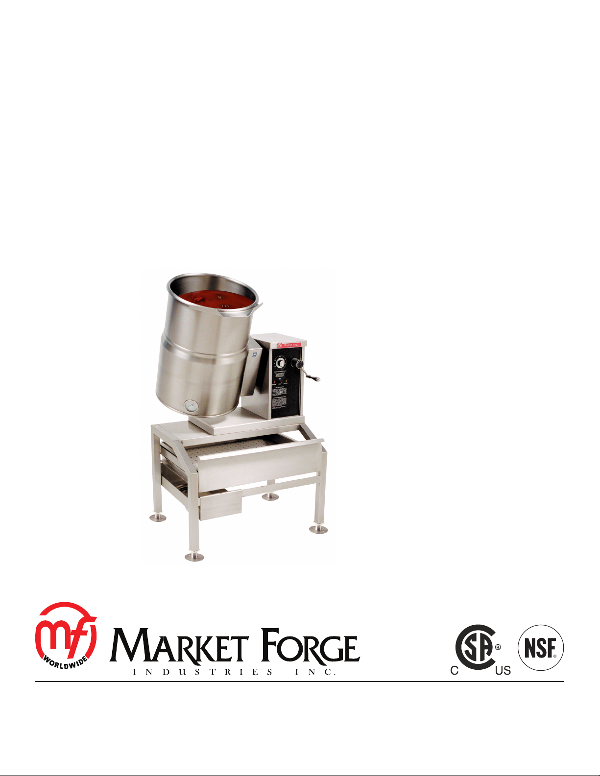
ELECTRIC TILTING KETTLE W/HAND CRANK
INSTALLATION - OPERATION - MAINTENANCE
MODELS
FCT-6CE
FCT-10CE
FCT-12CE
44 Lakeside Avenue, Burlington, Vermont 05401 USA
Telephone: (802) 658-6600 Fax: (802) 864-0183
www.mi.com PN 14-0354 Rev A (9/14)
© 2014 - Market Forge Industries Inc.
Page 2

Your Service Agency’s Address:
Model
Serial number
Oven installed by
Installation checked by
Page 3

IMPORTANT
TABLE OF CONTENTS
WARNING: Improper installation, adjustment, alternation,
service or maintenance can
cause property damage, injury or death. Read the installation, operation and maintenance instructions thoroughly
before installing or servicing
this equipment.
FOR YOUR SAFETY
Do not store or use gasoline or
other ammable vapors or liquids in the vicinity of this or any
other appliance.
The information contained in this
manual is important for the proper installation, use, and maintenance of this oven. Adherence
to these procedures and instructions will result in satisfactory
baking results and long, trouble free service. Please read
this manual carefully and retain
it for future reference.
INSTALLATION
Service Connections ..................................................... 2
Installation on Counter Surface ............................................ 3
OPERATION
Operating Instructions .................................................... 4
MAINTENANCE
Cleaning ................................................................ 5
ERRORS: Descriptive, typographic or pictorial errors are
subject to correction. Specications are subject to change
without notice.
Page 4

Service Connections
ELECTRICAL CHARACTERISTICS
MODEL pH
FCT-6CE 1 7.5 36 7.5 32.6 7.5 31.3 - - - - - -
3 7.5 20.8 7.5 18.8 7.5 18.1 7.5 11.4 7.5 10.4 7.5 9
FCT-10CE
FCT-12CE
1 12 57.6 12 52.2 12 50 - - - - - -
3 12 33.3 12 30.2 12 28.9 12 18.3 12 16.7 12 14.5
DIMENSIONS
MODEL A B C D E F G H J K L M
FCT-6CE 12
[305]
FCT-10CE 16
[406]
FCT-12CE 16
[406]
208V 230V 240V 380V 415V 480V
kW Amp kW Amp kW Amp kW Amp kW Amp kW Amp
14
[356]
15
[381]
17
[432]
25
[638]
25.5
[648]
27.5
[699]
15
[387]
19
[486]
19
[486]
25
[638]4 [102]
28-7/8
[734]4 [102]
28-7/8
[734]4 [102]
28
[711]
28
[711]
30
[762]
6-1/8
[156]
6-1/8
[156]
6-1/8
[156]
13
[330]
13
[330]
13
[330]
12-3/4
[324]
12-3/4
[324]
12-3/4
[324]
10
[254]
12-3/4
[324]
12-3/4
[324]
6-1/8
[156]
6-1/8
[156]
6-1/8
[156]
SAFETY RELIEF VALVE
D
B
C
4X WELD NUTS
5/16-18 UNC
A (ID)
E
14.5 [368]
20.875 [530]
1.875 [48]
EC
ELECTRICAL CONNECTION
POUR PATH
F
L
DIMENSIONS ARE IN INCHES [MM]
FACE OF WALL
EC
J
10
[254]
K
G
1.25 [32]
M
INSTALLATION
Figure 1
2
Page 5

Installation on Counter Surface
1. Position kettle on counter allowing sufcient rear
clearance from wall to tilt freely and completely without obstruction.
2. Mark (4) corner locations of kettle base, as shown in
Figure 1.
3. Remove kettle from counter and locate position of 4
holes as per above drawing. Drill four 7/6” diameter
holes.
4. Apply a continuous bead of Silastic or other equivalent sealant along the complete perimeter edge of the
kettle base.
5. Use 5/16 - 18 x 1 1/2” Hex Cap Screws with suitable
at washers to bolt down.
6. Wipe off excess sealant.
7. A Control Box with power supply equivalent to Elec-
MARK (4) CORNERS
ON COUNTER
trical Rating of kettle should be located conveniently
nearby.
8. A waterproof electrical connection for power supply to
console housing must be provided.
9. Ground kettle to terminal provided inside console
housing.
10. Turn power ON and check for proper operation.
1 1"/4
32mm
14 1/2"
368mm
18"
457mm
10"
254mm
12 1/2"
317mm
2 1/4"
57mm
Figure 2
3
INSTALLATION
Page 6

Operating Instructions
COOKING:
1. Ensure that the external electrical shut-off to kettle is
on.
2. Check pressure gauge for correct cold kettle reading.
Reading should be 25-30 In.Hg of vacuum. If reading
is not low enough, follow VENTING procedure prior
to using kettle.
3. Place power switch in ON position.
4
5
1
4. Preheat kettle by placing thermostat knob at ‘10’ and
wait until TEMPERATURE light goes off.
NOTE: Preheating should not be used when cooking
milk and egg food products which adhere to
hot cooking surfaces. These foods should be
placed into kettle before heating is begun.
5. Add food to be cooked into kettle.
6. Place thermostat knob at required temperature setting from ‘1’ to ‘10’ coinciding with a temperature
range from roughly 90°F to 300°F (32°C to 149°C) in
the reservoir. Approximate cooking temperatures with
water at various thermostat settings are as follows:
THERMOSTAT
SETTING
°F °C
4 90° 32°
5 125° 52°
6 160° 71°
7 195° 91°
8 231° 110°
9 273° 134°
10 300° 149°
APPROXIMATE
TEMPERATURE (WATER)
6
3
2
Figure 3
ITEM DESCRIPTION
1 Hand Crank
2 Power Switch
3 Low Water Indicator Light
4 Temperature (Heat Indicator) Light
5 Temperature Control Thermostat
6 Vacuum/Pressure Gauge
7. When cooking is nished, set thermostat knob and
power switch to OFF position.
8. Pour nished product from kettle using tilt handle. Be
careful to avoid splashing.
9. Add water to kettle for cleaning purposes.
10. Wash kettle thoroughly. See CLEANING procedure.
OPERATION
4
Page 7

The kettle interior and exterior should be thoroughly
washed after each use in preparation of a different food.
1. Add water and mild detergent to the kettle immediately after use.
2. Scrub kettle interior with a nylon brush.
NOTE: Never scrape the inside of kettle with metal
tools, steel scouring pads, or abrasive cleaners. Scratches will result which will spoil the
kettle’s general appearance and make it
harder to clean and maintain in a sanitary
condition.
3. Loosen food which is stuck to kettle by allowing it to
soak at a low temperature setting.
4. Rinse with clear water and dry.
WARNING
Do not hose down unit under any condition.
Failure to comply will void warranty.
5. Wipe down exterior, rinse and dry.
Cleaning
5
MAINTENANCE
 Loading...