

Page 1

FCT-CE SERIES
ELECTRIC TILTING KETTLE W/HAND CRANK
PARTS AND SERVICE MANUAL
EFFECTIVE SEPTEMBER 12, 2014
The Company reserves the right to make substitution in the event that items specied are not available.
ERRORS: Descriptive and/or typographic errors are subject to correction.
44 Lakeside Avenue, Burlington, Vermont 05401 USA Telephone: (802) 658-6600 Fax: (802) 860-3732
Superseding All Previous Parts Lists.
MARKET FORGE INDUSTRIES
www.mi.com
P/N 14-0355 Rev A (9/14)
Page 2

TABLE OF CONTENTS
MAINTENANCE ........................................................................3
ILLUSTRATED PARTS LIST
EXTERIOR VIEW ......................................................................4
EXPLODED VIEW .....................................................................6
SEPTEMBER 12, 2014 2 FCT-CE SERIES TILTING KETTLE W/HAND CRANK
Page 3
MAINTENANCE
MODELS
FCT-4CE - 4 gallon (16 liters), tilting electric countertop kettle
FCT-6CE - 6 gallon (23 liters), tilting electric countertop kettle
FCT-10E - 10 gallon (38 liters), tilting electric countertop kettle
FCT-12CE - 12 gallon (46 liters), tilting electric countertop kettle
VENTING
Check vacuum/pressure gauge when kettle is cold.
Gauge should be in the vacuum zone between 25-30 In.
Hg. If not, air is present which must be vented (removed)
for proper heating. Use the following procedures to vent
air.
1. Place power switch in ON position; kettle empty.
2. Set temperature control thermostat to ‘10’. Heat kettle
until heat indicator light goes off.
3. Using a 7/16” wrench, open bleed vent one full turn
for 10 seconds and close.
4. Cool kettle. Check for proper vacuum of 25-30 In. Hg.
If reading is not low enough, repeat entire procedure,
steps 1-3.
FILLING-JACKET RESERVOIR
The reservoir water level must be maintained at or above
the minimum needed to submerge the heating elements.
If the low water light turns on during use, the water level
is not adequate and the low water protection control has
automatically shut off the heating elements.
Use the following procedure to ll reservoir. Check vacuum/pressure gauge to ensure that there is no pressure in
kettle when adding water.
1. Turn thermostat and power switch to OFF position.
2. Remove 7/16” vent tting from bleed vent on back of
kettle. Insert a funnel into vent opening and add prescribed volume of water. For 6 gallon models, add 50
ounces (1.5 liters). For 10 and 12 gallon models, add
100 ounces (3 liters).
3. Replace and tighten vent tting.
4. With kettle in upright position, the low water light
should be off at this time. If so, follow venting procedure to vent air from reservoir Venting. If low water
light is not off, repeat Filling Jacket Reservoir.
CAUTION
Before adding water to the reservoir, water
supply should be analyzed to ensure that
hardness is no greater than 2.0- grains per
gallon and pH level is within the range of 7.0-
8.5. Water which fails to meet these standards
should be treated, or ionized distilled water
with sodium used. EQUIPMENT FAILURE
CAUSED BY INADEQUATE WATER QUALITY
IS NOT COVERED UNDER WARRANTY.
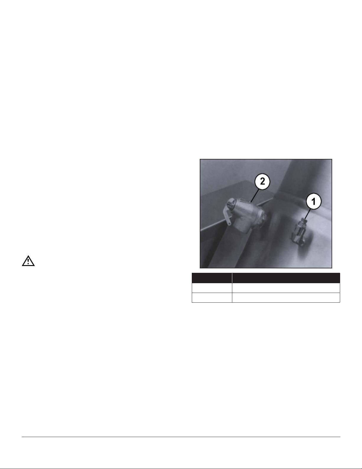
ITEM DESCRIPTION
1 Bleed Vent
2 Pressure Relief Valve
SEPTEMBER 12, 2014 3 FCT-CE SERIES TILTING KETTLE W/HAND CRANK
Page 4

EXTERIOR VIEW
SEPTEMBER 12, 2014 4 FCT-CE SERIES TILTING KETTLE W/HAND CRANK
Page 5

EXTERIOR VIEW
ITEM PART NO. DESCRIPTION
1 97-5004 Cover, Kettle Enclosure FCT-6CE
97-5006 Cover, Kettle, Enclosure FCT-10CE & -12CE
2 97-5005 Bolt, Enclosure Cover
3 97-5010 Air Vent 7/16”, Assy.
4 97-5009 Valve, Relief, Safely (50 PSI)
5 97.5007 Handle, Tilt, FCT-6CE, -10CE & -12CE
6 97-5008 Knob, Handle, Tilt
7 97-5011 Switch, Power
8 97-5026 Collar, Retaining
9 08-6362 Switch, Interlock
10 97-5144 Cover, Access, Element
11 97-5003 Cover, Box, Control
12 10-7934 Liquid Level Control
13 20-0043 Contactor
14 10-5069 Section, Terminal Block
10-5070 End, Terminal Block
15 97-5024 Gasket FCT-6CE, Element
97-5025 Gasket FCT-10CE & -12CE, Element
16 10-7935 Probe
17 10-3425 Connector 1/4 x 1/4
18 97-5145 Tube, Copper, FCT-6CE
19 97-5146 Tube, Copper, FCT-10CE & -12CE
20 97-5002 Gauge, Pressure
21 97-5147 Plate, Mounting
22 10-6307 Knob Thermostat
23 09-6493 Controller, Temperature (thermostat)
24 97-0572 Potentiometer, Remote
25 09-6474 Sensor, temperature
26 20-0007 Light. Low Water
27 20-0007 Light, Temperature
- Elements Heating FCT-6CE
97-5015 208V,7.5KW
97-5016 220V or 380V 7.5KW
97-5017 240V or 415V 7.5KW
97-5018 480V 7.5KW
- Elements Heating FCT-10CE & -12CE
97-5019 208V 12KW
97-5021 240V, or 415V 12KW
97-5020 220V/380V 12KW
97-5022 480V 12KW
28 97-5150 Panel, Control
29 97-5149 Cover, Box, Trunnion FCT-10CE & -12CE
97-5148 Cover, Box, Trunnion FCT -6CE
30 10-5562 Logo, Casting. M.F
SEPTEMBER 12, 2014 5 FCT-CE SERIES TILTING KETTLE W/HAND CRANK
Page 6

EXPLODED VIEW
SEPTEMBER 12, 2014 6 FCT-CE SERIES TILTING KETTLE W/HAND CRANK
Page 7

EXPLODED VIEW
ITEM PART NO. DESCRIPTION
1 97-6499 Pressure Gauge Plate 1 1
2
3
4 97-5002 Pressure Gauge 1 1
5 97-5620 “O” Ring 1 1
6 97-5046 Connetor - female 1 1
7 97-5000 Connector - male 1 1
8 97-6500 Reducer Bushing 3/8 x 1/4 1 1
9 97-5618 Temperature Probe 1 1
10 97-6501 Connector - male 1 1
11 97-6502 Bottom Cover Gasket 1
12 97-6504 Bottom Cover 1
13
14
15 97-6506 Trunnion Box Cover 1
16 97-6508 Trunnion Box Cover 1
17 97-6510 Console Decal 1
18 97-5013 Dial 1 1
19 98-6162 Temperature Pilot - Red 1 1
20 97-6512 Temperature Pilot - Amber 1 1
21 97-6513 Power Switch 1 1
22 98-6047 Rotary Shaft Seal 1 1
23 97-6515 Mounting Plate 1 1
24 97-5047 Temperature Control 1 1
25 97-5617 Potentiometer complete with wires & hardware 1 1
26 97-6516 Bearing L.H. 1 1
27 97-6517 Set Screw 3/8-16 x 1/2 2 2
28 97-6518 Actuator 1 1
29 97-5414 Interlock Siwtch 1 1
30 97-6519 Bearing R.H. 1 1
31 97-5052 Ground Lug 1 1
-
-
97-6503 Bottom Cover Gasket 1
97-6505 Bottom Cover 1
-
-
97-6507 Trunnion Box Cover 1
97-6509 Trunnion Box Cover 1
97-6511 Console Decal 1
97-6320 Earth ID Tag 1 1
Washer #10 2 2
Hex Nut 10-32 2 2
Hex Screw 5/16-18 x 1/2 1 1
Machine Screw 10-32 x 1/2 2 2
FCT-4CE & FCT-6CE
QTY
FCT-10CE & FCT-12CE
QTY
SEPTEMBER 12, 2014 7 FCT-CE SERIES TILTING KETTLE W/HAND CRANK
Page 8

EXPLODED VIEW
ITEM PART NO. DESCRIPTION
32 97-6520 Base 1 1
33
34
35 97-5577 Tilt Handle 1 1
36 97-6521 Direction Label 1 1
37 97-6522 Tilt Arm 1 1
38
39 97-6523 “O” Ring 1 1
40 97-6524 Gear Box 1 1
41 97-6525 Key 1 1
42 97-6526 Socket Hd. Screw M6 x 2.5mm 4 4
43
44 97-6527 Liquid Level Control 1 1
45 97-5609 Contactor 208/240V 2 2
46 10-6963 Terminal Block 3 3
47 98-6186 End Section 1 1
48 97-5657 Component Mounting Plate 1 1
49 97-6528 Element Access Cover 1 1
50 97-6529 Element Access Cover Gasket 1 1
51 97-6530 Element Access Brace 1 1
52
53
54
55
56
57 97-5015 Element Assy., 208V, 7.5 kW 1
-
-
-
-
97-5609 Contactor 380, 415, 480V 1 1
-
-
-
-
-
97-5017 Element Assy., 240/416V, 7.5 kW 1
97-5016 Element Assy., 220/380V, 7.5 kW 1
97-5018 Element Assy., 480V, 7.5 kW 1
97-5019 Element Assy., 208V, 12 kW 1
97-5020 Element Assy., 220/380V, 12 kW 1
97-5021 Element Assy., 240/416V, 12 kW 1
97-5022 Element Assy., 480V, 12 kW 1
Hex Nut 3/8-16 NC 6 6
Washer 3/8” 6 6
Set Screw 1/4-28 x 1/4 1 1
Washer M6 4 4
Internal Tooth Washer 1/4” 1 1
Hex Nut 1/4-20 1 1
Hex Screw 5-16-18 x 3/4 4 4
Lock Washer 5/16 4 4
Screw 10-32 x 3/8 Brass NI Plated 6 6
FCT-4CE & FCT-6CE
QTY
FCT-10CE & FCT-12CE
QTY
SEPTEMBER 12, 2014 8 FCT-CE SERIES TILTING KETTLE W/HAND CRANK
 Loading...