

Page 1
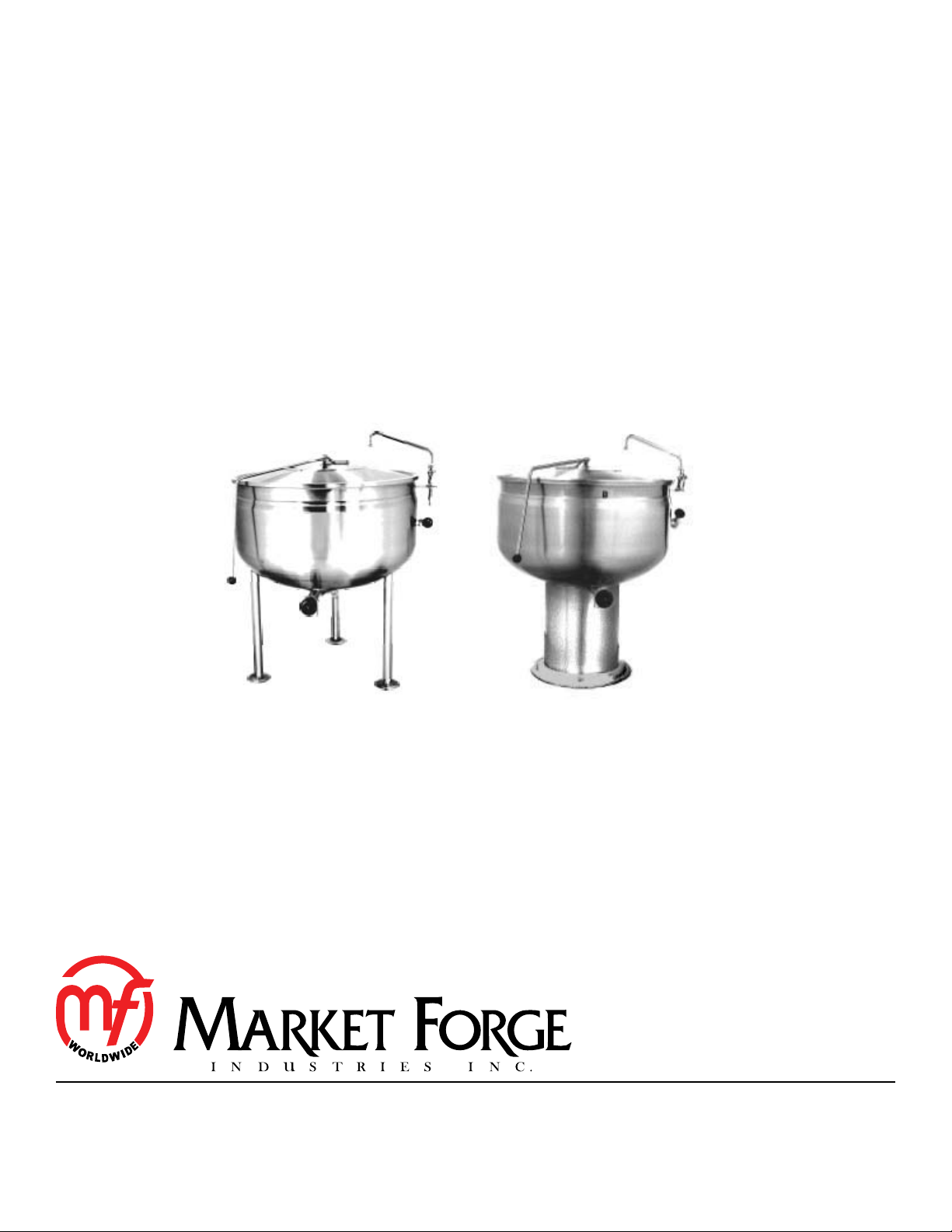
F-LF AND F-PF SERIES
FULLY JACKETED DIRECT STEAM STATIONARY KETTLES
INSTALLATION - OPERATION - MAINTENANCE
TRI-LEG MODELS
F-20LF
F-30LF
F-40LF
F-60LF
F-80LF
44 Lakeside Avenue, Burlington, Vermont 05401 USA
Telephone: (802) 658-6600 Fax: (802) 864-0183
www.mi.com PN 14-0346 Rev B (10/15)
© 2015 - Market Forge Industries Inc.
PEDESTAL MODELS
F-20PF
F-30PF
F-40PF
F-60PF
F-80PF
Page 2

Your Service Agency’s Address:
Model
Serial number
Kettle installed by
Installation checked by
Page 3

IMPORTANT
TABLE OF CONTENTS
WARNING: Improper installation, adjustment, alternation,
service or maintenance can
cause property damage, injury or death. Read the installation, operation and maintenance instructions thoroughly
before installing or servicing
this equipment.
FOR YOUR SAFETY
Do not store or use gasoline or
other ammable vapors or liquids in the vicinity of this or any
other appliance.
The information contained in this
manual is important for the proper installation, use, and maintenance of this kettle. Adherence
to these procedures and instructions will result in satisfactory
baking results and long, trouble free service. Please read
this manual carefully and retain
it for future reference.
INSTALLATION
Introduction .............................................................. 2
Service Connections ..................................................... 3
Installation Instructions ................................................... 5
OPERATION
Operating Instructions .................................................... 6
MAINTENANCE
Cleaning ................................................................ 7
ERRORS: Descriptive, typographic or pictorial errors are
subject to correction. Specications are subject to change
without notice.
Page 4

Introduction
All F-PF and F-LF direct connected steam jacketed kettles
are direct steam operated pressure vessels of a doublewall stainless steel construction forming a steam chamber
(jacket) enveloping the kettle bowl surface. All kettles are
stationary, oor mounted in xed positions either on legs
with adjustable anged feet (LF models) or pedestal (PF
models).
CAPACITIES
• F-20LF and F-20PF - 20 gallons (76 liters)
• F-30LF and F-30PF - 30 gallons (114 liters)
• F-40LF and F-40PF - 40 gallons (152 liters)
• F-60LF and F-60PF - 60 gallons (227 liters)
• F-80LF and F80PF - 80 gallons (303 liters)
FUNCTIONING MODE
Direct connected steam jacketed kettles consist of a
stainless steel bowl and a stainless steel jacket which envelopes the surface of the bowl, thus forming a sealed
pressure vessel (chamber) into which steam is introduced
by means of a manual control valve.
The kettle bowl is the container for the food product which
ideally should be of a liquid or semi-liquid consistency to
achieve complete contact with the bowl surface and thus
fully absorb the heat transmitted through that surface.
The temperatures required for the cooking process to
function adequately must be greater than the boiling point
of the liquid food product. Further, the greater the steam
pressure used, the higher the temperature and conse-
quently the quicker the cooking process. For example,
steam pressurized at 30 p.s.i. attains a temperature of
274 degrees Fahrenheit (135 degrees Celsius).
INSTALLATION
2
Page 5

Service Connections
F-LF LEG BASE KETTLES
DIMENSIONS
MODEL A B C D E F G H J K L
F-20LF 26
[660]
F-30LF 29.5
[749]
F-40LF 33
[838]
F-60LF 35.5
[902]
F-80LF 42
[1067]
15.75
[400]
17.5
[445]
19.25
[489]
20.5
[521]
23.75
[603]
37
[940]
37
[940]
37
[940]
40.5
[1029]
40.5
[1029]
27.5
[699]
31
[787]
34.5
[846]
37
[940]
43.88
[1114]
19
[483]
17.25
[438]
15.5
[394]
17.75
[451]
14.13
[359]
14.25
[362]
16
[406]
18
[457]
17.5
[445]
22
[559]
16
[406]
17.75
[451]
19.5
[495]
20.75
[527]
27.5
[699]
22.88
[581]
25
[635]
29.88
[759]
32.38
[822]
36.13
[918]
30.63
[778]
29.69
[754]
29.13
[740]
32.13
[816]
35.5
[902]
18.75
[476]
17
[432]
15.25
[387]
17.5
[445]
14
[356]
64.5
[1638]
68
[1727]
71.5
[1816]
77.5
[1969
82.88
[2105]
DIMENSIONS ARE IN INCHES [MM]
45°
SAFETY RELIEF
VALV E
HW
CW
OPTIONAL
FAUCET BRACKET
3.5 [89]
3 [76] FOR F-80LF
B
C
SERVICE CONNECTIONS
S Steam Supply - 3/4” (19mm) IPS, 5-35 PSI (0.3-
2.5 kg/cm2). Optional 5-50 PSI (0.3-3.5kg/cm2)
CW/HW Cold and Hot Water - 3/8” (10mm) NPT Female
for Cold and Hot Water to Kettle Faucet
S
Ø H
TRI-LEG (F-20LF)
D
A
QUAD-LEG
(ALL OTHER
MODELS)
S
J
CR Condensate Return - 1/2” (13mm) IPS
FLANGED FOOT DETAIL
4 EQUALLY SPACED
Ø7/16 [11] HOLES ON
3 [76] B.C. (2.835 [72] FOR F-80LF
HW
CW
L
S
E
CR
K
NOTE: DIMENSIONS E AND F ARE BASED ON
Ø2” DRAW-OFF VALVE
CLOSED 5.5 [140] - 5 [127] FOR F-80LF
OPEN 7.5 [191] - 6.88 [175] FOR F-80LF
BASED ON Ø2” DRAW-OFF VALVE
Figure 1
3
F G
INSTALLATION
Page 6

Service Connections
F-PF PEDESTAL BASE KETTLES
DIMENSIONS
MODEL A B C D E F G H J K L M
F-20PF
F-30PF
F-40PF
F-60PF
F-80PF
DIMENSIONS ARE IN INCHES [MM]
SAFETY RELIEF
VALV E
26
[660]
29.5
[749]
33
[838]
35.5
[902]
42
[1067]
HW
CW
15.75
[400]
17.5
[445]
19.25
[489]
20.5
[521]
23.75
[603]
45°
37
[940]
37
[940]
37
[940]
40.5
[1029]
40.5
[1029]
27.5
[699]
31
[787]
34.5
[876]
37
[940]
43.5
[1105]
19
[483]
17.25
[438]
15.5
[394]
17.75
[451]
14.5
[368]
S
14.25
[362]
16
[406]
18
[457]
17.5
[445]
18.75
[476]
16
[406]
17.75
[451]
19.5
[495]
20.75
[527]
24
[610]
16.88
[429]
16.88
[429]
19.63
[498]
19.63
[498]
19.63
[498]
30.63
[778]
29.69
[754]
29.13
[740]
32.13
[816]
15.88
[403]
18.75
[476]
17
[432]
15.25
[387]
17.5
[445]
14.25
[362]
SERVICE CONNECTIONS
S Steam Supply - 3/4” IPS (19mm) at 5-35PSI (0.3-
2.5 kg/cm2), Optional 5-50PSI (0.3-3.5 kg/cm2)
CR Condensate Return - 1/2” IPS (13mm)
CW/HW Cold and Hot Water - 3/8” (10mm) O.D. tubing
for cold and hot water to optional kettle fill faucet
64.5
[1638]
68
[1727]
71.5
[1816]
77.5
[1969]
84
[2134]
65
[1651]
68
[1727]
71.5
[1816]
77.5
[1969]
83
[2108]
OPTIONAL
FAUCET BRACKET
3.5 [89]
D
A
B
C
NOTE: DIMENSIONS E AND F ARE BASED ON
Ø2” DRAW-OFF VALVE
S
J
MIN. CLEARANCE
SIDES 3 [76]
BACK 0.5 [13]
Figure 2
PEDESTAL DETAIL
4 HOLES Ø7/16 [11]
45°
EQUALLY SPACED
ØH
FRONT
M
S
E
CLOSED 5.5 [140]
OPENED 7.5 [191]
BASED ON Ø2” DRAW-OFF VALVE
HW
CW
CR
K
F
G
INSTALLATION
4
Page 7

Installation Instructions
1. Select a location to provide drainage directly below
the tangent draw-off valve.
2. Mark hole locations through anged adjustable feet
on F-LF models and through pedestal base on F-PF
models. Remove kettle.
3. On hole locations marked, drill holes and insert expansion shields to accommodate 5/16” size lag bolts.
4. Reposition kettle. On F-LF models level kettle by
making necessary adjustment on anged foot.
5. Bolt down kettle and seal with Silastic or other equivalent sealing compound. Sealant must be applied not
only to bolt heads but also around anges or pedestal
base making contact with oor surface to fulll NSF
requirements.
6. Install a steam control valve at a convenient location
near kettle on the incoming steam line (3/4” size pipe).
7. Connect steam line to the kettle, making sure there
is a steam control valve strainer fairly convenient to
the kettle.
8. Connect kettle condensate return line to a drain or to
a boiler return line. Each kettle return line must have
a suitable steam trap. Boiler return lines must have a
check valve.
9. Safety relief valve on kettle must not be plugged as it
is set to relieve excess pressure in the kettle.
10. If incoming steam pressure is greater than kettle maximum operating pressure then a pressure reducing
valve must be installed in the line.
11. If large amounts of water accumulate in the steam
line it will be necessary to install one or more ball oat
traps in the line to eliminate the water.
12. A steam line pressure gauge is also recommended
to determine the actual amount of steam coming to
the kettle.
13. Check for proper operation.
5
INSTALLATION
Page 8

Operating Instructions
CAUTION
The appliance and its parts are hot. Use care
when operating, cleaning and servicing the
appliance.
1. Ensure that draw-off valve is closed.
2. Fill kettle with product to desired level.
3. Slowly turn the steam control valve ON to full open
position (counter clockwise).
4. The water or food should boil 2 - 3 gallons per minute. If it does not then incoming pressure and piping
should be checked to determine that it is adequate to
operate the kettle efciently.
5. Regulate steam control valve depending on type of
food being prepared.
6. When food is cooked, turn off steam, remove food
and clean kettle immediately to prevent residue from
drying on kettle bowl surface.
OPERATION
6
Page 9

Your kettle should be cleaned immediately after each use.
1. Ensure that steam supply is OFF.
2. Pre-rinse inside of kettle thoroughly and drain to remove any food particles.
3. Using a nylon brush, clean kettle with a mild detergent and warm water rinse. Never use steel wool or
scouring powder as it will scratch stainless steel.
4. Open the tangent draw-off valve to allow soap and
water solution to drain. Rinse with clean water.
WARNING
If you are cleaning a valve that is assembled
to a kettle be sure the kettle is completely
empty of any product.
5. By hand, turn the large hex nut counterclockwise on
draw off valve until it is completely disengaged from
thread. Grasp knob to valve and slowly pull out valve
stem and disc. Do not allow disc to come in contact
with hard surfaces since damage to disc may occur
and result in valve leakage. Wash the valve stem,
disc and handle. Insert nylon brush with detergent
into interior of valve body and tangent draw-off tube
and brush vigorously.
Cleaning
6. Replace valve stem assembly and engage hex nut
fully by hand. Flush kettle with clean warm water.
7. Leave valve open when kettle is not in use.
CAUTION
Do not use cleaning agents that are corrosive.
Use of cleaning agents that contain chloride, acids or
salts are corrosive and may cause pitting and corrosion
when used over a period of time; this will reduce the life
of the appliance.
Pitting or corrosion are not covered by warranty.
Follow the recommended cleaning instructions. Use a
mild detergent, warm water and rinse thoroughly.
7
MAINTENANCE
 Loading...