

Page 1
SERVICE & PARTS MANUAL
Models:
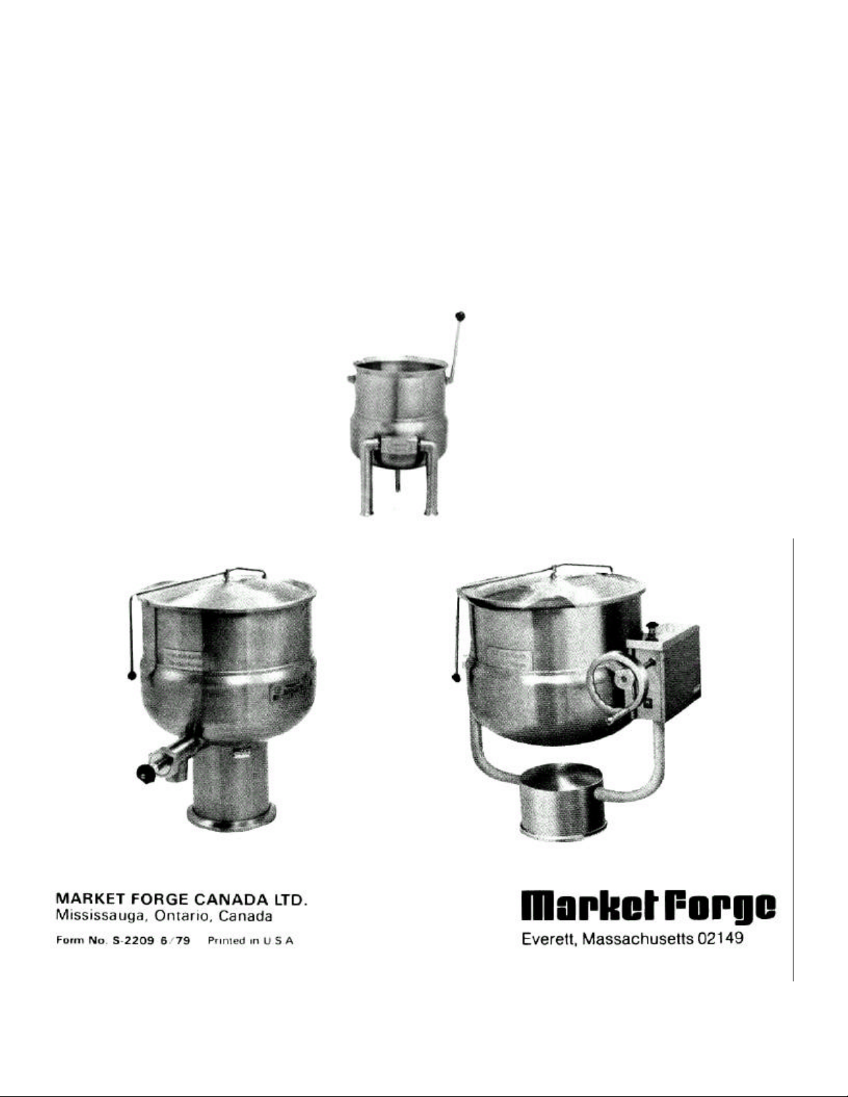
Direct Connected Steam Jacketed Kettles
Table-Top
Stationary
Tilting
Page 2

TABLE OF CONTENTS
…………………...
2.2.1
Table
-
Top Kettles
......…………………......
2-1
Paragraph Page Paragraph Page
SECTION 1 INTRODUCTION
1.1 Description ……............……………….... 1-1
1.1.1 Table-Top Kettles............……………….. 1-1 4.2 Preventive Maintenance.………..……………...... 4-1
1.1.2 Stationary Kettles ........………………….. 1-1
1.1.3 Tilting Kettles .......….…………………...... 1-2
1.2 Service ..................………………………... 1-2 4.3.1 Draw-off Valve Repairs .......……………………... 4-1
SECTION 2 INSTALLATION
2.1 Receiving ..................……………………….. 2-1
2.2 Installation. ............………………………...... 2-1 5.2 Ordering Information ………………………….......... 5-1
2.2.2 Leg Mounted Kettles....………………...... 2-1
2.2.3 Pedestal Mounted Kettles ……………..... 2-2
2.3 Installation Check-Out ....………………….. 2-3
2.3.1 Stationary & Table-Top Kettles ………... 2-3
2.3.2 Tilting Kettles ..........…………………...... 2-3
SECTION 3 OPERATION
3.1 Operation ...........………………………....... 3-1
3.2 Cleaning Procedure.........…………..…….. 3-1
Figure Page Figure Page
SECTION 2 INSTALLATION SECTION 5 ILLUSTRATED PARTS LIST
2-1
2-2
2-3
2-4
Table-Top Kettle Mounting .....….. 2-1 5-1 Tilting Kettle Components .....………….. 5-2
Flange Detail — Leg Mounting .... 2-2
Pedestal Assembly ......……......... 2-2
Pedestal Sealing .............……….. 2-3
LIST OF ILLUSTRATIONS
SECTION 4 MAINTENANCE
4.1 General .....................……….……………………. 4-1
4.2.1 Tilting Mechanism Lubrication
4.3 Repair and Replacement .………………………..
SECTION 5 ILLUSTRATED PARTS LISTS
5.1 General ...................……………………………….... 5-1
4-1
4-1
LIST OF TABLES
Table Page Table Page
SECTION 5 ILLUSTRATED PARTS LIST
Tilting Kettle Components ....…... 5-2 5-3 Cover Components ...........…………………. 5-3 5-1
5-2
Draw-off Valve Components ....... 5-3
iii
Page 3

A-1
APPENDIX A
STEAM INPUT REQUIREMENTS OF DIRECT CONNECTED KETTLES
The table below lists recommended delivered boiler horsepower for each kettle, and includes conversions to
steam flow expressed in pounds of steam per hour. The required delivered steam pressure for all kettles is 15 PSI
(7 kg/cm2}.
KETTLE MODEL
FT-5, LFT-5 5 19 .32 11
FT-10, LFT-10 10 38 .64 21.9
F-20L, F-20P, FT-20L, FT-20P, FT-20LV, FT20PV
F-30L, F-30P, FT-30L, FT-30P, FT-30LV, FT30PV
F-30LF, F-30PF 30 114 3.82 131.7
F-40L, F-40P, FT-40L, FT-40P, FT-40LV, FT40PV
F-40PF, F-40LF 40 152 5.09 175.6
CAPACITY
gals. liters
20 76 1.27 43.9
30 114 1.91 65.9
40 152 2.49 85.9
DELIVERED
BOILER HP
STEAM FLOW
(Ibs./hr)
F-60L, F-60P, FT-60L, FT-60P, FT-60LV, FT60PV
F-60LF, F-60PF 60 227 6.36 219.5
F-80L, F-80P, FT-80L, FT-80P, FT-80LV, F-80PV
F-80LF, F-80PF 80 303 7.95 274
F-100L, F-100P, FT-100L, FT-100P, FT-100LV,
FT-100PV
F-100LF, F-100PF 100 379 9.54 329
F-125L, F-125P 125 474 7.95 274
F-150L, F-150P 150 565 9.54 329
60 227 3.82 131.7
80 303 5.09 175.6
100 379 6.36 219.5
S-2209
Page 4

SECTION 1 INTRODUCTION
1-1
S-2209
This service and pa
rts manual contains general information, installation, operating, trouble
-
shoot
ing, and
maintenance information for the Market Forge direct connected steam jacketed kettle. Also included are parts
lists, with accompanying diagrams showing each replaceable part.
1.1 DESCRIPTION
The Market Forge direct connected steam
jacketed kettle is a steam operated pressure ves sel designed for cooking. It consists of a stain
less steel kettle with double-wall construction,
forming a surrounding chamber around the
lower 2/3 of the kettle into which steam is introduced as a source of heat for cooking. Steam input plumbing is equipped with a manual control
valve. Units are supplied mounted on legs or a
pedestal base, in tilting and stationary models,
and in capacities ranging from 5 to 150 gallons
(19 to 565 liters). Safety valves are standard on
all units except table-top models, on which a
safety valve is optional.
1.1.1. Table-Top Kettles
Table-top kettles are available in 5 to 10 gal
lon (19 and 38 liter) capacities, and are mounted
in trunnion assemblies which must be mounted
to a cabinet top. The trunnion pivots contain
steam input and return connections. Tilting is
accomplished manually by pulling a handle af
fixed to the kettle rim to rotate the kettle in its
trunnion mounts.
Applicable model designations include:
FT-5 [5 gallon (19 liter) capacity]
FT-10 [10 gallon (38 liter) capacity]
1.1.2 Stationary Kettles
These units consist of larger capacity kettles
mounted in fixed position on legs or pedestal
bases. They are equipped with tangent draw-off
valves for the removal of kettle contents. Hinged,
self-leveling, counterbalanced lids cover the
kettle openings. Units are available with a steam
jacket around the lower 2/3 of the kettle surface
("2/3 jacketed") or around the entire kettle sur
face ("full jacketed").
Applicable model designations include:
F -30PF. F-40PF. F-60PF. F-80PF. F-100PF:
Pedestal mounted, full jacketed, stationary
kettles of 30, 40, 60, 80, 100 gallon (114, 152,
227, 303, 379 liter) capacity.
F -30LF, F-40LF. F-60LF. F-80LF. F-100LF:
Leg mounted, full jacketed stationary kettles of
30. 40, 60, 80, 100 gallon (114, 152, 227. 303,
379 liter) capacit y.
F -20P. F-30P, F-40P. F-60P. F-80P. F-100P,
F -125P. F-150P:
Pedestal mounted, 2/3 jacketed stationary ket
tles of 20, 30, 40. 60, 80, 100, 125, 150 gallon
(76, 114, 152, 227, 303, 379, 474, 565 liter)
capacity.
F -20L F-30L. F-40L F-60L. F-80L F-100L,
F -125L F-150L:
Leg mounted, 2/3 jacketed stationary kettles of
20, 30. 40, 60, 80, 100, 125, 150 gallon (76,114,
152, 227, 303, 379, 474, 565 liter) capacity.
Page 5

30, 40, 60, 80, 100
gallon
(76, 114, 152,227,
40. 60, 80, 100
gallon
(76, 114, 152,227,
1-2
DIRECT CONNECTED KETTLE
1.1.3 Tilting Kettles
These units consist of larger capacity kettles
mounted on legs or pedestal bases, suspended from
trunnion mounts, and fitted with heavy duty tilting
mechanisms operated by manually turning a ha
ndwheel. A drain valve in the bottom of the jacket
permits removal of excess conden-sate.
Applicable model designations include:
FT-20L FT-30L FT-40L, FT-60L. FT-80L FT-100L:
Leg mounted, 2/3 jacketed tilting kettles of 20, 30, 40,
60, 80, 100 gallon (76, 114, 152, 227, 303, 379 liter)
capacity.
FT-20P. FT-30P, FT-40P, FT-60P. FT-80P, FT-100P:
Pedestal mounted, 2/3 jacketed tilting kettles of 20,
FT-20PV, FT-30PV, FT-40PV. FT-60PV, FT-80PV. FT100PV:
Pedestal mounted, 2/3 jacketed tilting kettles of 20, 30,
303, 379 liter) capacity, equipped with integral steam
trap, check valve, and blow-down tube on safety valve.
1.2 SERVICE
Required service, both preventive and corrective,
is explained in Section 3. Should repairs be required, a
network of authorized agencies is available to assist
with prompt service. A current directory of Authorized
Service Agencies may be obtained by contacting:
Product Service Department Market
Forge 35 Garvey Street Everett,
Massachusetts 02149 Telephone:
303, 379 liter) capacity.
FT-20LV, FT-30LV, FT-40LV. FT-60LV. FT-80LV.
FT-100LV:
Leg mounted, 2/3 jacketed tilting kettles of 20, 30, 40,
60, 80, 100 gallon (76, 114, 152, 227, 303, 379 liter)
capacity, equipped with integral steam trap, check
valve, and blow-down tube on safety valve.
(617) 387-4100
Product Service Department Market Forge
Canada Ltd. 1375 Aimco Blvd., Unit 5
Mississauga, Ontario, Canada L4W 1B5
Telephone: (416) 621-9252
The model and serial numbers must be referenced
when corresponding with Market Forge.
S-2209
Page 6

SECTION 2 INSTALLATION
POUR
2.2.2
Leg
-
Mounted Kettles
2.1 RECEIVING
The kettle is shipped strapped and bolted to a skid
and covered in most cases by a carton which is nailed
to the skid; these must be carefully removed prior to
installation. Inspect each unit carefully. If any damage
has been incurred during shipment, report same within
2 days to both the carrier and Market Forge.
boiler DOES provide for condensate return.
both a Vz" {13mm) steam trap and a W
{13mm} check valve must be installed.
2.2 INSTALLATION
2.2.1 Table-Top Kettles
1. Make W (19mm) holes for kettle legs on cabinet
top using a knockout punch. Locate holes at least
15" {381mm} from rear wall for FT-5 and 16"
{406mm) from rear wall for FT-10. See Figure 1.
2. Remove mounting locknuts from kettle legs and
install in proposed location.
3. Replace the locknuts, fastening down until hand
tight. Place a level on the kettle rim. If the unit is
level, tighten locknuts. If not, level cabinet top
before tightening locknuts.
4. Install service connections to tagged locations, i.e.
steam in, condensate return, as required. (The
steam inlet is at the right side of the kettle seen
from front).
NOTE
Service lines to kettle should be clean and
checked for foreign matter before final hook -up to
kettle, and be installed by qualified personnel.
PATH
NOTE
If the steam boiler to which this kettle isto be
installed does NOT providefor condensate return,
a Vi" {13mm} steam trap must be installed in lieu
of a return line. If the
1. Level the unit in proposed location by turning the
adjustable flanged feet. The location selected
should provide drainage as close to the drain valve
(if supplied) as possible.
2. Install unit using 5/16" lag bolts and shields (by
others), 3 bolts per foot. See Figure 2-2.
2-1 S-2209
Page 7

2-2 DIRECT CONNECTED KETTLE
Figure 2-2 Flange Detail — Leg Mounting
3. Install service connections, i.e. steam in, condensate
return, to tagged locations as required.
NOTE
Service lines to kettle should be clean and
checked for foreign matter before final hook -up to
kettle, and be installed by qualified personnel.
NOTE
If the steam boiler to which this kettle is to be
connected does NOT provide for condensate
return, a steam trap must be installed in lieu of a
return line. If the boiler DOES provide for
condensate return, both a steam trap and check
valve must be installed in the return line.
2.2.3 Pedestal Mounted Kettles
1. Lay the kettle on its side on a cushioned surface to
prevent scratching, and slide the base collar up the
pedestal to expose the plate for removal. See
Figure 2-3.
2. Remove the four cap screws securing the plate and
slide it off the pedestal.
3. Prepare location by installing a %" (19mm} cast-in
stud at the plate center point.
S-2209
Figure 2-3 Pedestal Assembly
NOTE
A W (19mm) bolt and shield may be substituted
for a cast-in stud. The shield is installed in the
floor and the lag bolt threaded down through the
base plate after completion of Step 5.
4. Thread the four %" (10mm} leveling bolts into the
plate from the top and insert the plate over the stud.
5. Adjust the bolts until the plate is level.
6. Install a nut on the W (19mm} bolt (insert lag bolt if
alternate fastener is used) and secure plate to floor.
7. Check for level "set" of kettle by placing ket tle on
base-plate with screw holes aligned and applying a
carpenter's level at the kettle rim. If the kettle is
level, it can be fastened in plate with the four cap
screws. If not, the ket tle must be removed from the
base, the plate loosened, and leveling bolts
readjusted until level installation is attained.
Page 8

2.
3.
4.
3.
4.
5.
6.
7.
INSTALLATION
8. Slide base collar down to floor and seal top and
bottom using silicone sealant. See Figure 2-4.
Turn steam supply valve on slowly.
Pull safety valve lever. Observe that steam
escapes freely.
2-3
9. Install service connections, i.e. steam in,
condensate return, as required.
NOTE
Service lines to kettle should be clean and
checked for foreign matter before final hook-up
to kettle, and be installed by qualified personnel.
NOTE
If the steam boiler to which this kettle is to be
connected does NOT provide for condensate
return, a steam trap must be installed in lieu of a
return line. If the boiler DOES provide for
condensate return, both a steam trap and check
valve must be installed in the return line.
2.3 INSTALLATION CHECK-OUT
2.3.1 Stationary and Table-Top Kettles
1. Fill kettle part way with water.
Avoid valve outlet when operating safety
valve.
Observe that water comes to a boil in the ket tle. Allow approximately 2 to 5 minutes per
gallon of water.
2.3.2 Tilting Kettles
1. Fill kettle part way with water.
2. Open the petcock in the bottom of the jacket.
Use care in opening and closing petcock
when steam is in jacket.
Turn steam supply valve on slowly.
Allow steam to circulate in the jacket. This
will cause a large amount of condensate to
form, which will drain out of the bottom pet
cock.
When live steam starts to emit, close the pet
cock.
Pull safety valve lever. Observe that steam
es capes freely.
Avoid valve outlet when operating safety
valve.
Observe that water comes to a boil in the ket
tle. Allow approximately 2 to 5 minutes per
gallon of water.
WARNING
WARNING
WARNING
S-2209
Page 9

SECTION 3 OPERATION
Wash kettle and cover (if supplied) with mild
lon
brush. If food is stuck to the surface, soak, using a
3.1 OPERATING PROCEDURE
1. Ensure that steam supply to kettle is operat -
ing.
2. Ensure that draw-off valve (if supplied) is
tightly closed.
3. If draw-off valve is supplied, place solid disc
or perforated disc in kettle depending on
whether liquid is to be retained or drained.
4. Fill kettle with product to desired level.
5. Turn steam control valve on (counter-clock
wise) to full open position.
6. When product has reached desired tempera
ture, regulate heat as needed by turning
valve clockwise.
7. When product is cooked, close steam control
valve and remove product from kettle im-
mediately to prevent overcooking.
3.2 CLEANSlNG PROCEDURE
As with cleaning food soil from any cook-
ware, an important part of kettle cleaning is to
prevent foods from drying on. For this reason,
cleaning should be completed immediately after
cooked foods are removed. If time cannot be al-
lotted for immediate thorough cleaning, fill the
kettle with warm water and a mild detergent.
1.
detergent and lukewarm water, using a ny
little heat to loosen the food.
NOTE
NEVER use ordinary steel wool, or a steel
scraper of any description.
2. Drain the kettle and remove the disc in the draw-
off valve (if supplied). Rinse and dry.
3. If draw-off valve is supplied, it must be taken
apart and cleaned.
a) Turn the handle counter-clockwise.
b) Loosen the hex nut on the end of the handle
by turning it counter-clockwise.
c) Remove the valve carefully.
d) Wash the draw-off valve area thoroughly,
using a nylon brush.
e) Rinse and dry.
3-1
Page 10

SECTION 4 MAINTENANCE
4-1 S-2209
4.1 GENERAL
This section contains both preventive and
corrective maintenance information. Preventive
maintenance may be performed by maintenance
personnel at the establishment in which the ket -
tle is installed. It is recommended that user per
sonnel never attempt to make repairs or replace
ment to the equipment without the assistance of
authorized service. Assistance in service methods or a current directory of Authorized Service
Agencies may be obtained by contacting Market
Forge. See Subsection 1.2.
4.2 PREVENTIVE MAINTENANCE
The most important preventive maintenance
operation on the steam jacketed kettle is the
cleaning procedure after each use detailed in
Section 2. Additional preventive maintenance
operations are presented in this section.
4.2.1 Tilting Mechanism Lubrication
Lubrication of the hand wheel tilting mechanism on kettles so equipped is the only required
preventive maintenance other than daily cleaning. Inspect the worm screw, tilting gears and
bearings occasionally (at least once a year). Lubricate as required, using a graphite lubricant
(part #10-3512) or equivalent.
4.3 REPAIR AND REPLACEMENT
In the event that the kettle fails to operate
correctly, the difficulty should first be isolated to
either the kettle itself or its steam supply. While
mechanical problems are obvious faults of the
kettle, any deficiency in volume or pressure of
steam should be traced to the steam generator
and the cause det ermined. Steam input requirements are listed in Appendix A, Steam Input
Requirements of Direct Connected Kettles.
4.3.1 Draw-off Valve Repairs
4.3.1.1 Common Leak Repairs
To repair a valve leak, the source must first
be determined. Leaks from around the valve
stem are corrected by replacing the "0" ring.
Dripping from the valve outlet which occurs with
the valve tightly closed indicates faulty seating
of the valve disc against the valve seat. Dripping
of this kind is often corrected by cleaning residue
from disc and seat using very fine emery.
4.3.1 2 Valve Seat Lapping
Should either the disc or seat be found to be
damaged, it is necessary to either replace the
entire valve, or perform the lapping procedure as
follows:
1. Disassemble the valve and clean both the
disc and the valve seat.
2. Attach the handle to the stem with the valve
bonnet removed.
3. Apply a good grade of fine lapping compound
to the disc and insert it into the valve to make
light contact against the seat.
4. Rotate the stem disc against the seat by turn ing the handle, allowing the stem to wobble
in the space normally occupied by the bon
net. Continue with light pressure until com
pound dries.
5. Reassemble and test for leaks with valve
closed. If dripping occurs, repeat the lapping
procedure as many times as required to ob tain a watertight seal.
Page 11

SECTION 5 ILLUSTRATED PARTS LISTS
5-1 S-2209
5.1 GENERAL
This section contains a complete listing of all
replaceable parts of direct connected steam jacketed
kettles.
5.2 ORDERING INFORMATION
Orders for repair parts should be directed to the
nearest authorized part s distributor. For a current
Market Forge Authorized Parts Distributor list, contact:
Product Service Department Market
Forge 35 Garvey Street Everett,
Massachusetts 02149 Telephone:
(617) 387-4100
Product Service Department Market Forge
Canada, Ltd. 1375 Aimco Blvd., Unit 5
Mississauga, Ontario, Canada L4W 1B5
All orders should contain the Market Forge part
number, the part description, and the model and serial
number of the kettle for which the part is ordered.
Page 12

FIG. 5-1
ITEM NO. PART NO. DESCRIPTION
1 20-0035 Worm Gear
2 10-0200 Trunnion '0' Rings
3 10-4755 Steam Trap
4 20-01 22 'Y' Strainer
5 20-0119 Check Valve
6 20-0024 Handwheel
7 20-0131 Bearing, Bronze
8 20-01 34 Bearing, Thrust
9 20-0221 C-Clips
10 20-0033 Worm
11 20-0036 Worm Locking Key
12 10-3661 Steam Control Valve
13A 20-0207 Shaft. 20 Gallon Kettle
13B 20-0208 Shaft, 30 Gallon Kettle
13C 20-0026 Shaft, 40 Gallon Kettle
13D 20-0209 Shaft, 60 Gallon Kettle
13E 20-0210 Shaft, 80 Gallon Kettle
S-2209
Page 13

Faucet, 1 1/2
"
Valve
10-
4928
Hinged Cover:
20
gallon unit
20-
0160
ILLUSTRATED PARTS LIST
TABLE 5-2 DRAW -OFF VALVE COMPONENTS
DESCRIPTION PART NUMBER
Faucet, 2" Valve 20-0105
Faucet, 3" Valve 20-0106
Stem, 1 1/2" Valve 10-4967
Stem, 2" Valve 20-01 79
Stem, 3" Valve 20-0180
Nut, 1 1/2" Valve 10-4970
Nut, 2" Valve 20-01 90
Nut, 3" Valve 20-0191
Knob, 1 1/2" Valve 10-4971
Knob, 2" Valve 20-0192
Knob, 3" Valve 20-0193
Wing Nut, 1 1/2" Valve 10-4972
Knob Nut, 2" Valve 20-01 94
Knob Nut, 3" Valve 20-0195
Bonnet, 1 1/2" Valve 10-4968
Bonnet, 2" Valve 20-0196
Bonnet, 3" Valve 20-0197
"0" Ring, 1 1/2" Valve 10-4969
"0" Ring, 2" Valve 20-0198
"0" Ring, 3" Valve 20-0199
Drain Screen 1 1/2" Valve 20-0016
Drain Screen 2" Valve 20-0200
Drain Screen 3" Valve 20-0201
TABLE 5-3 COVER COMPONENTS
DESCRIPTION PART NUMBER
30 gallon unit 20-0161
40 gallon unit 20-0001
60 gallon unit 20-0162
80 gallon unit 20-0163
100 gallon unit 20-01 64
Lever for cover: 20 gallon unit 20-0165
30 gallon unit 20-0166
40 gallon unit 20-0003
60 gallon unit 20-0167
80 gallon unit 20-01 68
100 gallon unit 20-0169
S-2209
 Loading...