

Market Forge ETP-5G Installation Manual
INSTALLATION AND OPERATION
MANUAL AND PARTS LIST
GAS FIRED STEAMER
MODELS
ETP-5G
ETP-10G
___________________________________________________________________________
S-6501 35 Garvey Street, Everett, MA 02149-4403
Rev. ' 0/ T
el: (617) 387-4100, (866) 698-3188
Fax: (
617) 387-4456, (800) 227-2659
custserv@ mfii.com, www.m fii. com
1
INSTALLATION, OPERATION AND PARTS MANUAL, MODELS ETP-5G & ETP-10G
IMPORTANT NOTES FOR INSTALLATION AND OPERATION
Retain this manual for future reference.
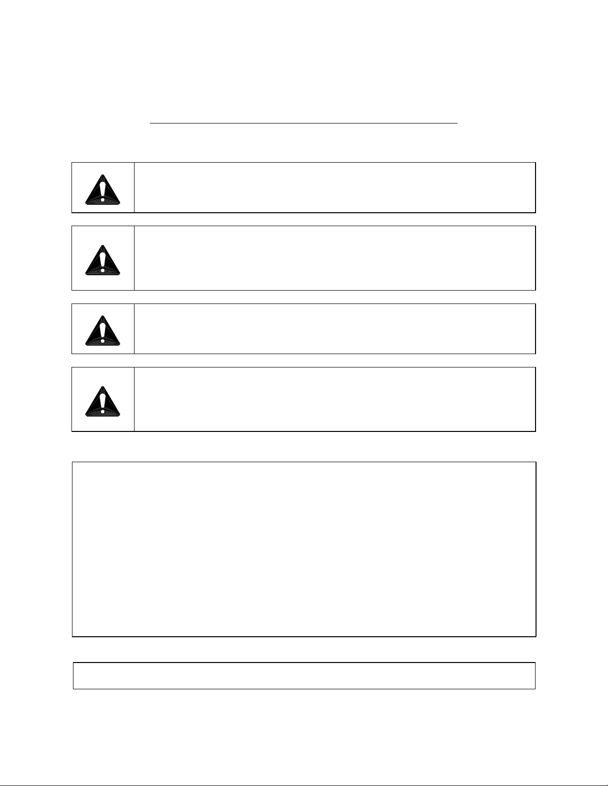
This is the safety alert symbol. It is used to alert you to potential
personal injury hazards. Obey all safety messages that follow this
symbol to avoid possible injury or death.
WARNING: Improper installation, adjustment, alteration, service or
maintenance can cause property damage, injury or death. Read the
installation, operating and maintenance instructions thoroughly
before installing, servicing or operating this equipment.
FOR YOUR SAFETY: Do not store or use gasoline or other
flammable vapors and liquids in the vicinity of this or any other
appliance.
PURCHASER: Instructions to be followed in the event that the
operator of this appliance smells gas must be posted in a prominent
location. This information shall be obtained by consulting the local
gas supplier.
IMPORTANT
Do not attempt to operate this unit in the event of power failure.
Adequate clearances must be maintained for safe and proper operation.
The appliance area must be kept free and clear of combustibles.
Do not obstruct the flow of combustion and ventilation air.
Contact the factory, the factory representative or a local service company to
perform maintenance and repairs should the appliance malfunction. Refer to
warranty terms.
Intended for commercial use only. Not for household use.
PART NUMBER 10205R3 2 2010-06-30

INSTALLATION, OPERATION AND PARTS MANUAL, MODELS ETP-5G & ETP-10G
TABLE OF CONTENTS
DESCRIPTION PAGE
1.0 SERVICE CONNECTIONS ...............................................4
2.0 INTRODUCTION .......................................................6
3.0 INSTALLATION ........................................................7
4.0 PERFORMANCE CHECK ...............................................14
5.0 OPERATION INSTRUCTIONS ...........................................15
6.0 PREVENTIVE MAINTENANCE ...........................................23
7.0 GENERAL TROUBLESHOOTING GUIDE ...................................29
8.0 MAINTENANCE ......................................................35
9.0 PARTS ..............................................................37
10.0 WIRING DIAGRAMS ..................................................50
PART NUMBER 10205R3 3 2010-06-30
INSTALLATION, OPERATION AND PARTS MANUAL, MODELS ETP-5G & ETP-10G
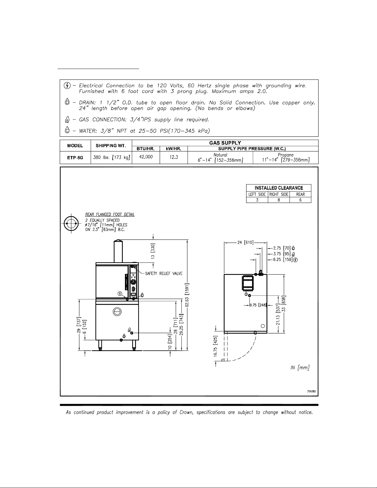
1.0 SERVICE CONNECTIONS
PART NUMBER 10205R3 4 2010-06-30

INSTALLATION, OPERATION AND PARTS MANUAL, MODELS ETP-5G & ETP-10G
1.0 SERVICE CONNECTIONS
PART NUMBER 10205R3 5 2010-06-30

INSTALLATION, OPERATION AND PARTS MANUAL, MODELS ETP-5G & ETP-10G
2.0 INTRODUCTION
DESCRIPTION
The ETP-5G and ETP-10G are gas fired pressureless steam cookers. The cooking
compartments are equipped with a three-piece door with inner gasket plate isolated from the
exterior surface. Door latch operates by slam action for positive sealing of the door. Operating
controls are displayed on a front-mounted panel and include indicator lights for ignition, ready
and cooking modes, a timer to set cook times and a selectable hold cycle to keep food warm
once cooked, a temperature display to monitor cavity temperature, and an illuminated
ON/OFF/DELIME switch. The ETP-5G is equipped with one generator, the ETP-10G with two.
Each stainless steel steam generator operates “0" psi (0 kPa) and is rated at 42,000 BTUH.
BASIC FUNCTIONING
The cooker is ready for operation when the READY light comes on.
At the end of the set interval, timer contacts switch to shut off the cooking operation and sound
a signal buzzer. The buzzer is silenced by returning the timer dial to the OFF position. In the
‘HOLD’ mode, the cooker will maintain a safe food holding temperature at or above 150°F.
Steam and liquids from each cooking cavity pass through a removable drain screen in the
cavity and into the tempering tank. When the appliance is shut off, the steam generators will
also drain into the tempering tank. The tempering tank condenses any residual steam and
tempers the waste water to 140°F or less.
PART NUMBER 10205R3 6 2010-06-30
INSTALLATION, OPERATION AND PARTS MANUAL, MODELS ETP-5G & ETP-10G
3.0 INSTALLATION
SETTING IN PLACE
The location of installation must be under an exhaust hood, which will remove water vapour
emitted when the cooker door is opened, and exhaust combustion fumes. Level the unit in final
location by turning the adjustable feet. Using the cabinet top as a reference, obtain level
adjustment left-to-right and front-to-back.
MECHANICAL CONNECTIONS
All electrical and plumbing connections are located on the rear panel of the unit. See
‘SERVICE CONNECTIONS’ on pages 4 and 5 for location of mechanical connections.
3.1 INSTALLATION CODES AND STANDARDS
Installation must conform with local codes, or in absence of local codes, with the National Fuel
Gas Code - ANSI Z223.1/NFPA 54, or the Natural Gas and Propane Installation Code, CSA
B149.1 as applicable.
1. The appliance and its individual shut off valve must be disconnected from the gas supply
piping system during any pressure testing of that system at pressures in excess of ½ psi
(3.5 kPa).
2. The appliance must be isolated from the gas supply piping system by closing its individual
manual shut off valve during any pressure testing of the gas supply piping system at test
pressures equal to or less than ½ psi (3.5 kPa).
Electrical grounding must be provided in accordance with local codes, or in the absence of local
codes, with the National Electrical Code ANSI/NFPA 70, or the Canadian Electrical Code, CSA
C22.2 as applicable.
Ventilation must be provided in accordance with local codes, or in the absence of local codes,
with ANSI/NFPA 96 Standard for Ventilation and Fire Protection of Commercial Cooking
Operations.
WARNING: Electrical grounding instructions - Units come equipped
with a three-prong (grounding) plug for your protection against
shock hazard and should be plugged directly into a properly
grounded three-prong receptacle. Do not cut or remove the
grounding prong from this plug. (120 VOLT UNITS ONLY)
WIRING DIAGRAM FOR APPLIANCE IS LOCATED ON RIGHT HAND SIDE PANEL OF THE
COOKER CABINET.
PART NUMBER 10205R3 7 2010-06-30

INSTALLATION, OPERATION AND PARTS MANUAL, MODELS ETP-5G & ETP-10G
3.0 INSTALLATION (Continued)
3.2 EXHAUST FANS AND CANOPIES
Canopies are set over ranges, ovens, kettles, etc., for ventilation purposes. It is
recommended that a canopy extend 6" past the appliance and be located 6' 6" from the
floor. Filters should be installed at an angle of 45 degrees or more with the horizontal. This
position prevents dripping of grease and facilitates collecting the run-off grease in a drip
pan, usually installed with the filter. A strong exhaust fan tends to create a vacuum in the
room and may interfere with burner performance or may extinguish pilot flames. Makeup air
openings approximately equal to the fan area will relieve such vacuum. In case of
unsatisfactory performance on any appliance, check with the exhaust fan in the “OFF”
position.
3.3 WALL EXHAUST FAN
Exhaust fans should be installed at least two feet above the vent opening at the top of the
unit.
3.4 CLEARANCES
Adequate clearance must be provided in aisle and at the side and back. Adequate
clearances for air openings into the combustion chamber must be provided, as well as for
serviceability. Minimum clearance from combustible and noncombustible construction, 3"
on left side, 8" on right side and 6" from back.
WARNING: These procedures must be followed by qualified
personnel or warranty will be voided. An open gap floor drain is
required immediately below the appliance drain. See page 12.
To Install:
1. Uncrate carefully. Report any freight damage to the freight company immediately.
2. Set the unit in place. Be certain to maintain the minimum clearances from combustibles
and non-combustibles.
3. For an appliance supplied with legs, level the appliance using a spirit level. Rear flanged
adjustable feet are provided for permanent anchoring to the floor. With the unit in location,
mark hole locations on the floor through the anchoring holes. Remove the steamer and drill
holes at marked locations on the floor. Insert proper anchoring devices.
4. Set steamer back in proper position.
PART NUMBER 10205R3 8 2010-06-30
INSTALLATION, OPERATION AND PARTS MANUAL, MODELS ETP-5G & ETP-10G
3.0 INSTALLATION (Continued)
5. Install bolts through anchoring holes and into anchors to secure the steamer to the floor.
Seal bolts and flanged feet with Silastic™ or equivalent silicone sealant.
6. After the drain is connected, check for level by pouring water onto the floor of the
compartment. All water should drain through the opening at the back of the compartment
cavity.
WARNING: For an appliance equipped with casters, the installation
shall be made with a connector that complies with the Standard for
Connectors for Moveable Gas Appliances, ANSI Z21.69/CSA 6.16
and a quick-disconnect device that complies with the Standard for
Quick-Disconnect Devices for use with Gas Fuel, ANSI Z21.41/CSA
6.9; adequate means must be provided to limit the movement of the
appliance without depending on the connector and the quickdisconnect device or its associated piping to limit the appliance
movement: the location where restraining means may be attached
is directly above the gas supply inlet pipe on the rear of the
appliance.
The water inlet connections must also be installed with a flexible
water supply tube, a quick disconnect and strain relief.
GAS CONNECTION:
1. The Serial and Rating Plate on the unit indicates the type of gas your unit is equipped to
burn. DO NOT connect to any other gas type.
2. A ¾” NPT line is provided at rear for the connection. Each compartment is equipped with
an internal pressure regulator which is set at 3.5" W.C. manifold pressure for natural gas
and 10" W.C. for propane gas. Use c” pipe tap on the burner manifold for checking
pressure.
An adequate gas supply is imperative. Undersized or low pressure lines will restrict the volume
of gas required for satisfactory performance. A steady supply pressure, between 6" W.C. and
14" W.C. for natural gas and 11" W.C. and 14" W.C. for propane gas is recommended. With all
units operating simultaneously, the manifold pressure on all units should not show any
appreciable drop. Fluctuations of more that 25% on natural gas and 10% on propane gas will
create problems, affecting burner operation. Contact your gas company for correct supply line
sizes.
PART NUMBER 10205R3 9 2010-06-30
INSTALLATION, OPERATION AND PARTS MANUAL, MODELS ETP-5G & ETP-10G
3.0 INSTALLATION (Continued)
Purge the supply line to clean out any dust, dirt or other foreign matter before connecting the
line to the unit. Use pipe joint compound which is suitable for use with LP on all threaded
connections.
Test pipe connections thoroughly for gas leaks.
WARNING: Never use an open flame to check for gas leaks. Check
all connections for leaks using soapy water before use.
NOTICE: If this equipment is being installed at over 2,000 feet altitude and was
not so specified on order, contact service department. Failure to install with
proper orifice sizing may void the warranty.
ELECTRICAL CONNECTION:
120 VAC-60 Hz - Single Phase
Units with this electrical rating are factory supplied with a three-wire cord and three-prong plug
which fits any standard 120V, three-prong grounded receptacle. A separate 15 amp supply is
needed for each unit.
PART NUMBER 10205R3 10 2010-06-30
INSTALLATION, OPERATION AND PARTS MANUAL, MODELS ETP-5G & ETP-10G
3.0 INSTALLATION (Continued)
PLUMBING CONNECTIONS:
NOTICE: Equipment not installed in accordance to these guidelines
may void the warranty.
WARNING: Plumbing connections must comply with applicable
Sanitary, Safety and Plumbing Codes.
WARNING: An obstructed drain can cause personal injury or
property damage.
Two water lines are provided. Connect water supply lines to the 3/8" copper tubes at the rear of
the steamer.
One line is for supply of water to the generator and one for cold condensate water to condense
live steam entering the drain line.
PART NUMBER 10205R3 11 2010-06-30
INSTALLATION, OPERATION AND PARTS MANUAL, MODELS ETP-5G & ETP-10G
3.0 INSTALLATION (Continued)
DRAIN CONNECTIONS:
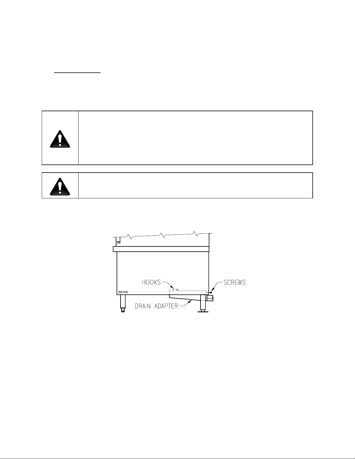
WARNING: Directly plumbing a drain line to the tempering tank may
cause personal injury or damage to the appliance. Not using the
supplied drain adapter will void your warranty.
If this equipment is being installed over an open floor drain, the
Drain Adapter is not required.
CAUTION: PVC OR CPVC are not acceptable materials for drains.
INSTALLING THE DRAIN ADAPTER
From the rear of the unit, position the drain adapter hooks through the slots in the floor of the
cabinet to and align with the holes at the rear and fasten in place with provided screws.
When making the drain connection to the 1½” NPT male thread of the drain adapter, use a pipe
wrench to firmly support the drain adapter nipple to prevent damage to the assembly.
PART NUMBER 10205R3 12 2010-06-30
INSTALLATION, OPERATION AND PARTS MANUAL, MODELS ETP-5G & ETP-10G
PART NUMBER 10205R3 13 2010-06-30
3.0 INSTALLATION (Continued)
WATER CONDITIONING: Untreated water contains scale producing minerals which can
precipitate onto the surfaces in the steam generator. Due to the temperatures in the steam
generator, the minerals can bake onto the surfaces and components. This can result in early
component failure and reduced product life. Water level probes become coated with scale.
Scale may bridge across the probe insulator from the metal extension which senses the water
level in the steam generator shell. Once this scale becomes wet, the water level control is
unable to maintain the proper water level in the steam generator.
STRAINERS and FILTERS will NOT treat equipment for scale reduction.
This equipment is furnished with an Aqua-Pure® Commercial Series water filtration system. An
initial flushing procedure for the filter system must be performed before using this equipment.
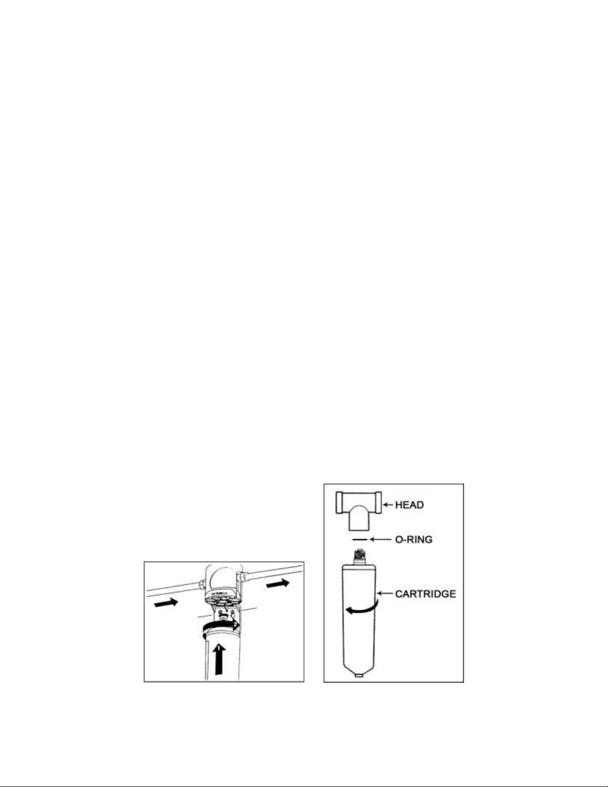
FILTER SYSTEM INSTALLATION SET-UP
1. Remove sanitary cap from cartridge. Install cartridge with a quarter turn to the right until
cartridge comes to a complete stop. (A “click” is heard). (Figure 1)
2. It is recommended that cartridges be replaced regularly, at no more than six-month
intervals, to be assured of optimum performance. (Figure 2)
To replace cartridge:
a. Shut off inlet water.
b. Open a downstream valve to relieve pressure.
c. Unscrew the cartridge in the direction shown in the illustration and discard.
d. Lubricate o-ring of new cartridge with water. DO NOT use petroleum jelly.
e. Install by turning new cartridge toward the right until it comes to a complete stop.
DO NOT over tighten. (Never use tools to tighten a cartridge).
f. Turn on inlet valve, bleed air through a downstream valve until water appears
clear, and check for leaks. System is now ready for use.
Figure 1 Figure 2
PART NUMBER 10205R3 13 2010-06-30
INSTALLATION, OPERATION AND PARTS MANUAL, MODELS ETP-5G & ETP-10G
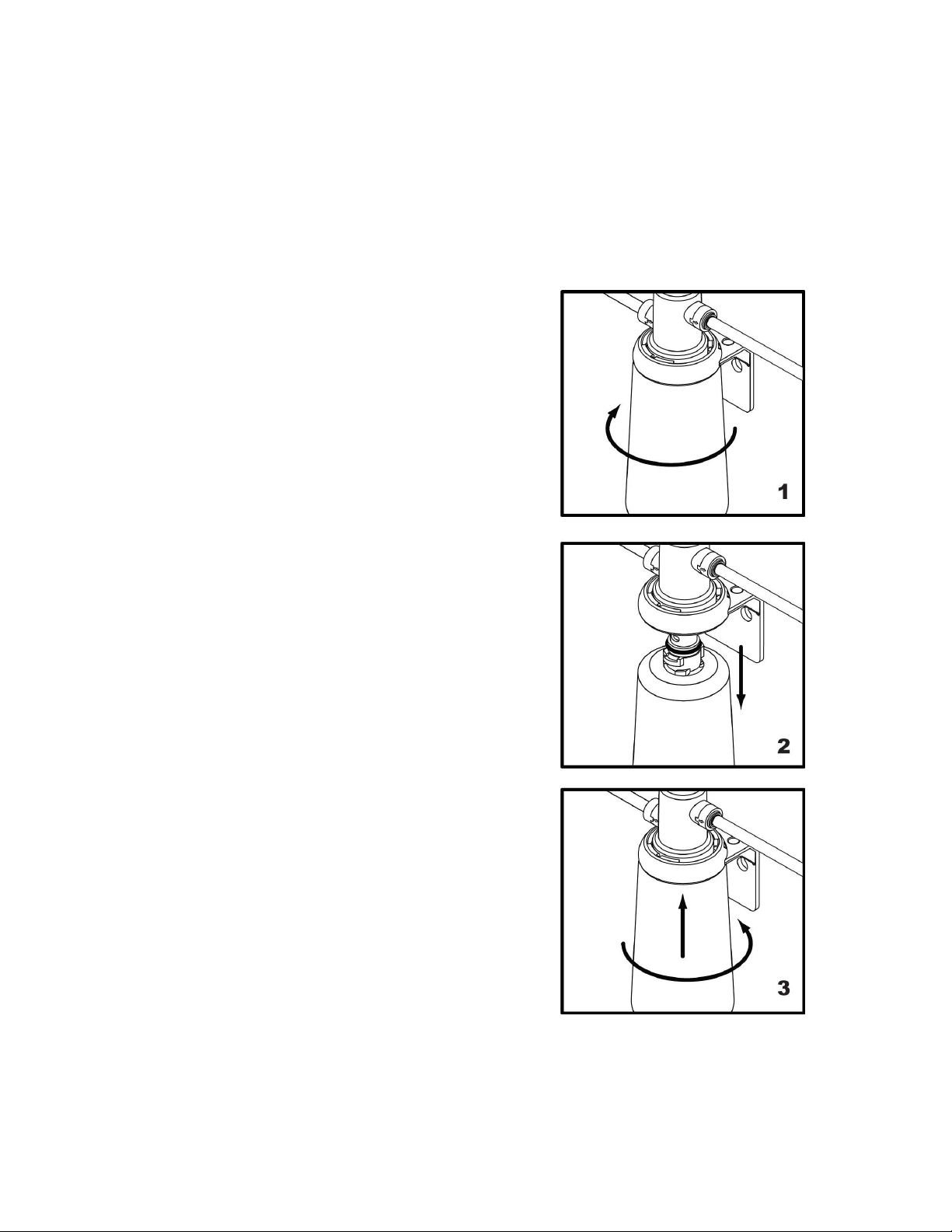
6.0 PREVENTIVE MAINTENANCE
FILTER CHANGE PROCEDURE
NOTE: This system is equipped with an internal shut-off valve.
1. Turn cartridge slowly to the left, about 1/4
turn, until it stops (when arrows line up). At
this position, both inlet and outlet ports are
closed and water pressure has been relieved.
2. Pull used cartridge straight down and discard.
Note: There may be a small amount of
residual water drainage after pressure is
relieved and during cartridge removal.
3. Moisten o-ring with a food grade lubricant and
push new cartridge into filter head. Turn
cartridge 1/4 turn to the right until it stops
(when arrows line up). Top surface of
cartridge will become flush with bottom of the
head when fully engaged.
4. Open downstream valve (if installed) and
flush new filter cartridge for two minutes,
expelling any trapped air and carbon fines.
Water may run cloudy with air but will quickly
clear.
5. Reset the monitor by inserting an opened
paper clip into the hole labeled “RESET”
Depress and hold the reset switch for five
seconds. Successful resetting is witnessed by
the unit going through its “reset sequence” of
blinking LED’s, namely, Green, Yellow, Red,
individually, followed by, Green/Yellow/Red
simultaneously.
PART NUMBER 10205R3 13A 2010-06-30
INSTALLATION, OPERATION AND PARTS MANUAL, MODELS ETP-5G & ETP-10G
4.0 PERFORMANCE CHECK
WARNING: The steamer and its parts are hot. Use care when
operating, cleaning or servicing the steamer. The cooking
compartment contains live steam. Stay clear while opening door.
Once the steamer is installed and all mechanical connections have been made, thoroughly test
the steamer before operation.
1. Check that proper water, drain and electrical and gas connections have been made.
2. Turn main power switch “ON”. After approximately 10 minutes, the “READY” light should
come on and should remain on, indicating that the water temperature is approximately 200°
Fahrenheit (93° Celsius).
3. Check that “IGNITION” light comes on when the burner pilot is ON.
4. When the “READY” light comes on, set timer to the “5 minute” position. With door open,
observe that no steam is entering the compartment and that the “COOKING” light is OFF.
5. Close compartment door. The “COOKING” light should now be illuminated and steam
should be heard entering the compartment after about 45 seconds.
6. The tempering tank does not discharge to drain until the water in the top of the tank reaches
130°F or the unit is shut off and the generators are allowed to drain.
7. Open compartment door and observe that steam supply to chamber is cut off and the
“COOKING” light goes “OFF”.
8. Close compartment door and let cooking cycle finish. When the timer returns to “0"
position, a buzzer will sound signaling the end of the cooking cycle. Buzzer must be
manually turned off by setting the timer to its “OFF” position.
PART NUMBER 10205R3 14 2010-06-30
INSTALLATION, OPERATION AND PARTS MANUAL, MODELS ETP-5G & ETP-10G
5.0 OPERATION INSTRUCTIONS
WARNING: In the event of main burner ignition failure, a 5 minute
purge period must be observed prior to re-establishing ignition
source. If so equipped, some units will automatically re-attempt
ignition.
WARNING: In the event a gas odor is detected, shut down
equipment at the main shut off valve and contact the local gas
company or gas supplier for service.
LIGHTING
1. Ensure power, gas and water supply is on.
2. Turn power switch “ON”.
3. Generator tank will begin filling with water.
4. Once water level has been reached, the ignition light will come on and remain on throughout
the operation of the appliance.
5. When the “READY” light comes on the steamer is ready for use.
SHUTDOWN
STAND BY
1. Set timer to “OFF” position and leave door slightly open.
END OF THE DAY
1. Set timer to “OFF”
2. Set power switch to “OFF”. Generator(s) will drain automatically.
3. Leave doors ajar.
PART NUMBER 10205R3 15 2010-06-30

INSTALLATION, OPERATION AND PARTS MANUAL, MODELS ETP-5G & ETP-10G
5.0 OPERATION INSTRUCTIONS (Continued)
COMPLETE SHUTDOWN
1. Set timer to “OFF” and turn power switch “OFF”. Generator will drain automatically.
2. Leave doors ajar.
3. Turn water supply “OFF”.
4. Turn gas supply “OFF”
5. Disconnect power supply.
PREHEATING
Before each initial operation of the cooker, and at any other time when the cooking
compartment is cold, a 5-minute preheating period is required. To preheat the cooker, put
steam source into operation and proceed as follows:
1. Close cooking compartment door.
2. Set 60-Minute Timer Dial to “5-minute” setting.
3. Turn off buzzer, which sounds to indicate pre-heating is complete, by setting the Timer Dial
to OFF position.
COOKING
CAUTION: Live steam and accumulated hot water in the
compartment may be released when the door is opened.
Before loading the cooker, be sure compartment is hot. See preheating instructions.
1. Slide pans of food into cooking compartment pan supports.
2. Close cooking compartment door.
3. Set timer cooking time:
a. HOLD - for holding cooked foods in a warm state. Will maintain the cooking cavity
at or above 150°F (65°C).
b. 60-MINUTE TIMER - for timed cooking.
PART NUMBER 10205R3 16 2010-06-30
 Loading...