

Page 1
Eco Tech
®
ELECTRIC STEAM COOKER
MODELS:
ET-3E
ET-5E
ET-6E
SB-ET-3E
SB-ET-6E
COVERING
• INSTALLATION
• OPERATION
• SERVICE & PARTS
INSTALLATION AND OPERATION MANUAL
An Employee-Owned Company
35 Garvey Street • Everett, MA 02149-4422 USA
Tel: (617) 387-4100 • Fax: (617) 387-4456
Outside MA Fax: 1-800-227-2659 E-mail: custserv@mfii.com Web site: www.mfii.com
Form No. S-2501 REV. E 5/03 Printed In U.S.A
Page 2

T able of Contents
PARAGRAPH PAGE
SECTION 1 INTRODUCTION
1.1 Description................................................... 1-1
1.2 Basic Functioning ........................................ 1-1
1.3 Service.......................................................... 1-1
SECTION 2 INSTALLATION
2.1 Assembly ..................................................... 2-1
2. 2 Setting in Place............................................. 2 - 1
2.3 Service Connections .................................... 2-1
2.3.1 Electrical Connections.................................. 2- 1
2.4 Reversing the Doors .................................... 2-1
SECTION 3 INITIAL SYSTEMS INSPECTION
3. 1 General ......................................................... 3-1
3.2 Warm-up ...................................................... 3-1
3. 3 Timed Steam Mode ...................................... 3- 1
3.4 Constant Steam Mode.................................. 3-1
3.5 Hold Mode ................................................... 3- 1
3. 6 High / Low Power Mode .............................. 3- 1
3.7 Low Water Warning..................................... 3- 1
3.8 Shut Down ................................................... 3- 1
PARAGRAPH PAGE
SECTION 4 OPERATION
4.1 Controls and Indicators ............................... 4-1
4.2 Operating Procedures .................................. 4-1
4.2.1 Startup and Preheating................................. 4-1
4.2.2 Cooking—Mechanical Controls................... 4- 1
4.2.3 Shutdown and Daily Cleaning...................... 4- 2
4. 3 Periodic Cleaning ......................................... 4-2
SECTION 5 TROUBLESHOOTING
5. 1 General ......................................................... 5-1
SECTION 6 MAINTENANCE
6. 1 General ......................................................... 6-1
6. 2 Daily Cleaning .............................................. 6-1
6.3 Preventive Maintenance .............................. 6-1
6. 4 Periodic Cleaning ......................................... 6-1
6. 5 Control Panel Electrical Service Access ....... 6- 2
6.6 Door Adjustment ......................................... 6-2
6.6.1 Door Alignment ........................................... 6 - 2
6.6.2 Door Latch Tension Adjustment ................. 6-2
6.6.3 Door Handle Tension Adjustment ............... 6-3
6. 7 Door Gasket Replacement ............................ 6- 3
6. 8 Heating Element Replacement ....................... 6-11
6.9 Ship-Board Assembly Replacement.............. 6-13
i
Page 3

1. Introduction
1.1 Description
The Eco Tech® represents the latest in counter top steam
technology, designed to apply the benefits of steam cooking
to today’s health-conscious menus. Ideal for batch cooking,
à-la-carte, and rethermalization of individual entrées, the Eco
Tech™ puts the power of steam on your counter top. The Eco
Tech™ is a pressureless steam cooker consisting of:
• 3, 5, or 6-pan cavity
• Electric pressureless generator (6, 9, or 12-kW inputs)
• Mechanical controls
• Low water indicator
• Hold feature
These features and functions will be discussed in greater detail in Section 3.
A steam-on-demand steam generator system gives quick
start-ups and efficient steam transfer to the cooking compartment, without the use of expensive vacuum pumps. In tests
for energy efficiency and cooking times performed in accordance with ASTM standards, the Eco Tech® yielded impressive results over other similar counter top steamers.
For continuous steam, set the selector timer knob to the “constant steam” position (the green area of the selector/timer
switch). The cooker will continue to steam until the switch is
moved to the “Hold/Idle” position.
If you desire a timed steam cooking cycle, just set the timer
knob to the cook time (up to 60 minutes).
In the timed steam mode, the cooker will create steam for the
duration of time you have set. Once the timer reaches the end
of its cycle (0 minutes), the buzzer will sound. The buzzer is
silenced by returning the timer knob to the “Hold/Idle” position, which ceases the steaming function. The generator will
continue to idle at 170°F.
Each unit is equipped with a standard steam-and-hold feature. At the completion of the cooking cycle, place the timer
knob to the “Hold/Idle” position.
The hold feature is controlled by a separate thermostat with
an additional temperature gauge mounted just below the control panel. The unit will now act as a holding cabinet until
you call for steam again. During this time, the generator will
continue to idle at 170°F.
With the “hold” feature, your Eco Tech® will keep cooked
foods at 160°F until you are ready to serve, giving you more
time between cooking and serving—it’s a Market Forge exclusive.
As your operation grows, so does your Eco Tech®. By
stacking multiple Eco Tech® models, you can accommodate
up to 10 pans, creating a complete high-output steam cooking system.
1.2 Basic Functioning
To begin operation, the power switch is pressed into the ON
position, illuminating the power light. Pour about 2 1/2 gallons water into the steam generator, located at bottom of cavity. DO NOT exceed the “MAXIMUM WATER LINE”.
Turn the timer to approximately 15 minutes. This will energize the heating elements. At the end of 15 minutes the buzzer
will go off, indicating that the unit is now ready to cook.
A steaming mode is selected with the timer/selector switch.
The steam generator is drained from the bottom of the unit.
You need at least a 4” deep steam pan underneath the unit.
1.3 Service
Required service, both preventative and corrective, is explained in Sections 6 and 7. Should repairs be required, a network of authorized agencies is available to assist with prompt
service. A current Directory of Authorized Service Agencies
may be obtained by contacting:
Product Service Department
Market Forge Industries, Inc.
35 Garvey Street
Everett, Massachusetts 02149
Telephone: (617) 387-4100
The Model and Serial Numbers must be referenced when
corresponding with Market Forge. The data plate containing the serial number is located on the top front of the
steamer (body panel).
1-1
Page 4

2.1 Assembly
2. Installation
The assembled Eco Tech® Pressureless Steam Cooker is
shipped in a carton on a skid. Steps required for assembly are
as follows:
1. Remove the carton and the unit off the skid.
2. Install the feet into the threaded mounting locations on
the bottom of the unit.
3. Install a rack supports to the left & right insideof the
cooking cavity mounting holes.
4. Install the vent strainer in the back inside the cooking
cavity.
5. Mount the drip trough to the front of the unit.
6. Slide the ala-carte shelf into place on the slide guides.
2.2 Setting in Place
If possible, a location should be selected under an exhaust
hood which will remove small amounts of vapor emitted from
the cooker during normal operation. Next, level the unit after
it is placed in its final location. This is accomplished by turning the bottom part of the adjustable feet. Using the cabinet
top as a reference, obtain level adjustment left-to-right and
front-to-back. MAKE SURE UNIT IS LEVEL
MODEL: ET-3E
AMPS
VOLTS
208V
60Hz
240V
60Hz
480V
60Hz
PHASE
1 E
3 E
1 E
3 E
1 E
3 E
6Kw
29
17
25
15
13
7
9Kw
43
25
38
22
19
11
MODELS: ET-5E & ET-6E
AMPS
VOLTS
208V
60Hz
240V
60Hz
480V
60Hz
Note: ET-3E 9kW & ET-5/6E 12kW factory options
PHASE
1 E
3 E
1 E
3 E
1 E
3 E
9Kw
43
25
37.5
22
19
11
12Kw
58
34
50
29
25
15
Table 2.0
2.4 Reversing the Doors
2.3 Service Connections
The only service connection at the back of the unit is the
electrical connection. Please see the illustrations and table
located in Table 2.1 for service connections, details, and dimensions.
2.3.1 Electrical Connections
CAUTION: USE COPPER WIRE ONLY FOR POWER
SUPPLY CONNECTIONS.
Please refer to Table 2.1 for details of electrical service connections.
Electrical connection power supply should utilize wire suitable for 90°C.
The Eco Tech® Pressureless Steam Cooker has a reversible
cooking compartment door for your convenience. This section contains instructions for reversing this door.
1 . Turn off power to the unit.
2 . Open the cooking compartment door
3. Remove the two screws that attach the top hinge to the
front of the unit.
4 . Slide the door upwards, off the bottom hinge.
5. Remove the two screws that attach the bottom hinge to
the front of the units.
6 . Remove the right and left side panels by unscrewing the
1 screw on each panel and sliding the panel down.
2-1
Page 5

2. Installation (continued)
7. Remove the door interlock assembly by unscrewing the
two nuts that hold it in place (assembly is attached to the
screws in the top right hinge mounting holes,
see fig. 2-1).
8. Remove the four screws in the right side hinge mounting
holes and install them in the left side hinge mounting
holes (where the hinges were originally mounted).
9. Using the nuts removed in step #6, reinstall the door interlock assembly onto the 2 screws in the lower left hinge
mounting holes (see fig. 2-1) by moving the assembly
over the cooking cavity to the other side of the unit.
Rotate the door interlock assembly 180° for installation, so that the switch is now facing up.
10. Reinstall the top hinge and screws into the right lower
hinge mounting holes. Rotate the hinge 180° for in-
stallation, so that the pin which the door rides on is now
facing up. The hinge must be rotated because it will now
function as the bottom hinge. DO NOT COMPLETELY
TIGHTEN THE HINGE MOUNTING SCREWS YET.
These will be used later for adjusting the door.
11 . Remove the door latch assembly from the face of the unit.
The 2 nuts mounting the door latch are located behind
the face of the unit and must be accessed where the right
side panel was removed.
14. To adjust the tension of the door latch, tighten both nuts
down until the springs are fully compressed, then back
each nut off 1 1/2 turn.
15. Rotate the door 180° for mounting.
16. Slide the remaining hinge into the top door bearing.
17. Slide the door and hinge assembly down onto the hinge
which you have already mounted to the front of the unit.
Use the two screws to mount the top hinge into the right
upper hinge mounting holes. DO NOT COMPLETELY
TIGHTEN THE HINGE MOUNTING SCREWS YET.
18. Slowly push the cooking compartment door closed until
it is latched.
19. The cooking compartment door can now be raised, lowered, and/or rotated into position by bumping it with the
palm of your hand or by using a small rubber mallet.
20. First, check the alignment at the front of the door by
making sure that the striker in the door is centered with
the latch mechanism on the front of the unit.
21. Square the door to the unit by raising or lowering the
hinge side of the door, keeping the latch centered with
the striker.
12 . Remove the two white hole plugs from the left door latch
mounting holes, and insert them into the right door latch
mounting holes (where the door latch assembly was
originally mounted).
13. Rotate the door latch assembly 180°, and install into
the left door latch mounting holes.
NOTE: Each stud on the latch assembly
should have a plastic washer, a spring, a plastic
washer and a Nyloc type nut,
22. Visually inspect the door. Be sure that the door is square
to the unit, the striker is centered with the latch, and the
gasket is in contact with the entire lip of the cooking
compartment.
23.
Gently open the cooking compartment door, taking care
not to move it out of position.
24. Tighten all 4 door hinge bracket mounting screws.
25. Close and visually inspect the door again, as described
in step 22.
26. Reinstall the left and right side panels, using the screws
for each panel.
2-2
Page 6
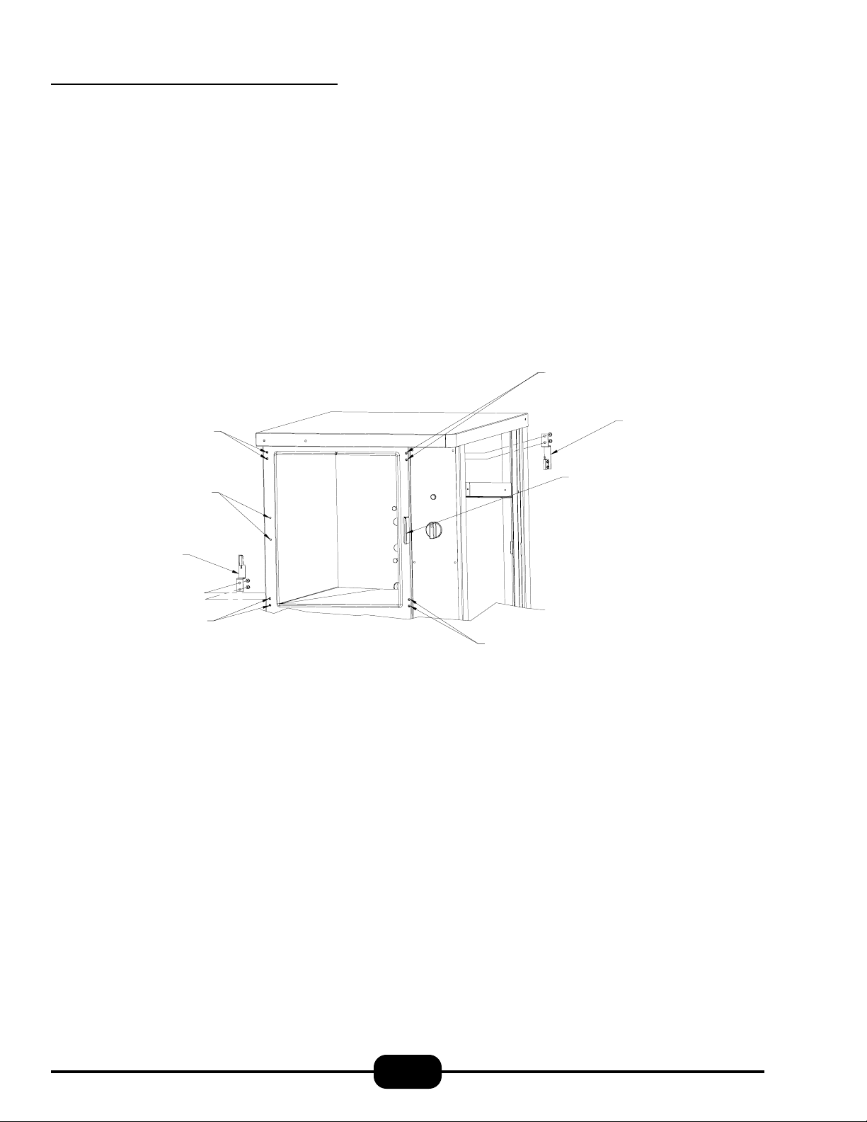
2. Installation (continued)
TOP LEFT HINGE
MOUNTING HOLES
TOP RIGHT HINGE
MOUNTING HOLES
INTERLOCK ASSEMBLY
ORIGINAL POSITION
LEFT DOOR LATCH
MOUNTING HOLES
INTERLOCK ASSEMBLY
POSITION WHEN DOOR IS
REVERSED
LOWER LEFT HINGE
MOUNTING HOLES
DOOR LATCH ASSEMBLY
ORIGINAL POSITION
LOWER RIGHT HINGE
MOUNTING HOLES
Fig. 2.1: Door Reversability
2-3
Page 7
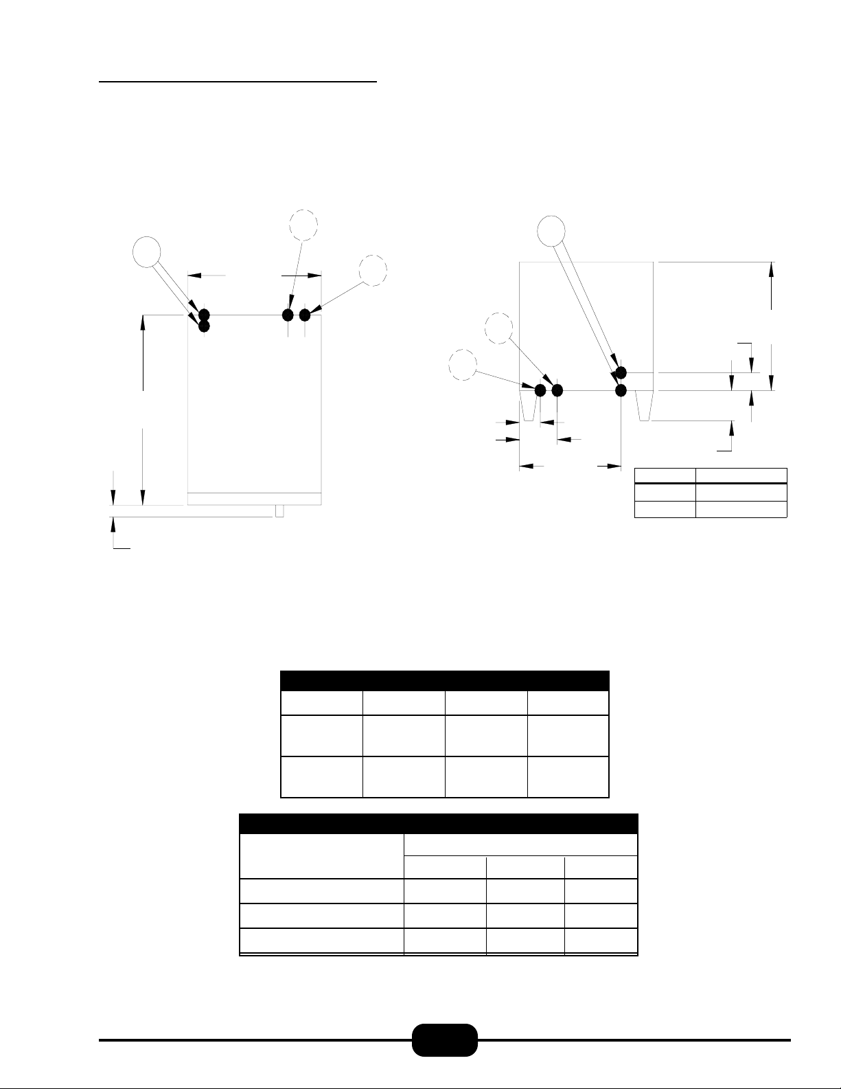
2. Installation (continued)
Table 2.1: Service Connections
Op tio na l - Auto Wate r
E
30"
[762 mm]
1.5"
[38 mm]
CW
24"
[610 mm]
3"
[76 mm]
TOP VIEW
Feed (Cold)
Optional - Drain Kit
D
6.5" (165mm)
9.63" (245mm)
E = Electrical Connection
CW = Sem i-Auto Water Feed (Factory Option)
D = D ra in K it (F a c to ry O p ti o n )
E
CW
D
18.8"
(447 mm)
REAR VIEW
[102 mm]
Model
5 & 6 Pan
3 Pan
2"
[51 mm]
4"
Height
28" [712 mm]
21.5" [546 mm]
SEE
BELOW
Note: Water used in this unit, should have hardness of no greater than 2.0 grains per gallon and pH level is
within the range of 7.0-8.5. Water which fails to meet these standards should be treated by installation of a
water conditioner. Equipment failure caused by inadequate water quality is not covered under warranty.
INTERNAL DIMENSIONS
Model Height Width Depth
ET-3E
ET-5 & 6E
10.7" 14.0" 22.5"
271 mm 356 mm 571 mm
17.2" 14.0" 22.5"
436 mm 356 mm 571 mm
CAPACITY
Pan Size Number of Pans
ET-3E ET-5E ET-6E
12" x 20" x 1" 68 10
12" x 20" x 21/2" 35 6
12" x 20" x 4" 23 4
2-4
Page 8

2. Installation (continued)
FRONT PANEL
Fig. 2.2: Wiring Diagram
2-5
Page 9

3. Initial Systems Inspection
3.1 General
This section contains information for you to test and familiarize yourself with the operation of the Eco Tech™.
After the cooker is completely assembled, all packaging materials removed, and all service connections are made, all systems must be given a thorough checkout before being put
into operation. We begin by making sure that the drain valve
is closed and the empty drain pan is in its proper position.
Pour about 2 1/2 gallons of water into the bottom of the cooking cavity or up to the “MAXIMUM WATER LINE”.
Mount both racks and the Ala - Carte - Shelf in place.
Confirm that all service connections are correct. Close the
cooking compartment door, and turn the timer knob to
15 minutes.
3.2 Warm-up
Push the power switch to the “ON” position. The heaters will
energize. After 15 minutes the buzzer will go off, indicating
that the steamer is ready to cook. The temperature gauge will
indicate a 212°F temperature. At this time you may choose
either to load food to cook or turn the timer knob to “hold /
idle” mode prior to actual cooking. In the hold / idle mode,
the temperature gauge will show a temperature of around
170°F.
3.3 Timed Steam Mode
Set the selector/timer knob to 10 minutes and close the door.
The temperature gauge will slowly register increasing temperatures up to 212°F.
When the timer reaches 0 minutes, the buzzer will sound.
The buzzer is silenced by returning the selector/timer knob
to the “hold / idle” position.
3.5 Hold / Idle Mode
You enter this mode by placing the selector/timer knob to the
“Hold / Idle” position. This mode only works if the steaming
cycle has been completed and the door has been left closed.
The cooking cavity will hold product between 150°F - 190°F
3.6 High / Low Power Switch
®
Your Eco-Tech
system. This feature allows smaller portions to be cooked
with less power. If your menu demands are reduced, the
Eco - Tech allows you to save energy. This is a Market Forge
exclusive!
comes with a unique “High / Low Power”
3.7 Low Water Signal
During cooking, the water in the steam generator will keep
evaporating. When the generator is nearly empty, the heaters, for safety reasons, will be turned off and a beeper will
sound, indicating an abrupt end to the cooking mode and a
need to add water until the beeper turns off.
3.8 Shut Down
No special procedure is necessary for shutting the unit down.
Simply press the power switch into the “OFF” position, and
open the drain valve at the bottom. The indicator lights on
the control panel will go out, and the generator will drain.
Then empty the drain pan.
Caution: When the unit is not in use, leave the cooking
compartment door slightly ajar to prolong the life of the
door gasket.
3.4 Constant Steam Mode
The constant steam mode overrides all other cooking modes.
This mode is entered by turning the selector/timer knob to
the “constant steam” position on the dial (green area). With
the knob set for constant steam, and the door closed, the temperature gauge should indicate a temperature of 212°F.
3-1
Page 10

4. Operation
4.1 Controls and Indicators
The controls and indicators used to operate the Eco Tech
pressureless steam cooker are listed and described in
Table 4.1.
4.2 Operating Procedures
This section includes general instructions for daily operation
of the Eco Tech™ pressureless steam cooker. You should review Sections 3.1 through 3.6 of this manual if you are unfamiliar with the functions of the Eco Tech™. If you require
more detailed technical information on the various Eco
Tech™ systems and their functions, please refer to Section 5
of this manual, “Principles of Operation.”
4.2.1 Startup and Preheating
The Eco Tech™ pressureless steam cooker requires a simple
startup procedure:
1. With the drain closed, pour clean water into the empty
steam generator up to the “ MAXIMUM WATER
LINE”
2. Press the power switch into the “on” position.
3 . With the door closed, turn the timer knob to 15 minutes.
®
The heaters will be energized. After 15 minutes, the buzzer will
go off, indicating that the steamer is ready to cook. You may
at this time either decide to cook in a constant steam/timer
mode or turn the timer knob to “hold/idle” mode to idle the
steamer around 170°F.
4.2.2 Cooking—Mechanical Controls
Note: The temperature gauge needs to indicate
temperatures above 150°F before cooking.
1. Slide pans of food into the cooking compartment pan
support racks.
2. Firmly close the cooking compartment door.
3. Begin steaming by rotating the selection/timer knob to
either the constant steam position or a desired cooking
time.
4. At the end of the cook cycle (the buzzer will sound when
the timer has timed out to zero), return the timer knob to
the “Hold/Idle” position, which will turn off the buzzer.
5. If the unit is in constant steam mode, it will continue to
provide steam to the cavity until the selector/timer is
turned to the “Hold/Idle” position. Opening the door will
interrupt the flow of steam to the cavity.
Table 4.1: Controls and Indicators
Located in the middle of the control panel. Pressing this button into the “on” position will
Power Switch
Timer Knob Located near the top of the control panel. Turn the timer knob to set the cook time.
Temperature Gauge
Constant Steam Position
No Water Alarm
High & Low Power Switch
supply power to the unit. Pressing this button into the “off” position will cut off power to
the generator.
Located at the bottom of the control panel, it is used to monitor the internal temperature
of the cooking compartment during the steam or “Hold/Idle” mode.
Located on the timer knob (selection/timer switch), the constant steam feature is entered
by turning the knob clockwise to the green area (marked constant steam).
Located below the power switch of the control panel. This will give an audible signal
when the generator needs to be refilled with clean water.
Located on the control panel just below the 60 Minute Timer. This switch allows the
end user to choose between power options. “HIGH” mode is for full capacity.
“LOW” mode is for reduced capacity.
4-1
Page 11

4. Operation (continued)
4.2.3 Shutdown and Daily Cleaning
After each period of daily operation, the steamer should be
drained and cleaned. Simply press the power switch into the
“OFF” position, and follow the cleaning steps outlined below.
1. Place an empty 4" deep steam pan under the steamer,
and turn drain valve to “OPEN.” Allow all water to drain
& cool before emptying the pan.
2. Allow the steamer to cool before removing rear strainer,
left and right racks, and ala-carte shelf.
3. Wash cooking compartment and steam generator interiors using a mild detergent. Rinse and dry thoroughly.
4. Remove drip/spill trough.
5. Wash all removed pieces with a mild detergent and nonabrasive pad. Rinse and dry thoroughly.
6. Replace all removed parts.
7. If “Total Concept” is needed repeat above procedure,
replacing vinegar with “Total Concept”.
7. Leave the door slightly ajar to prolong life of the door
gasket.
4.3 Periodic Cleaning
If you should experience build up of lime or mineral deposits
in the steam generator, it may be cleaned easily using vinegar & water. If dealing with severe scaling use Market
Forge’s descaling product, “Total Concept™” with water.
1. With drain closed, fill generator with 2 gallons water
and 1/2 gallon vinegar. Close door
2. Turn power switch to “ON”.
3. Place timer into “HOLD” mode. Let run for one hour.
4. Open door. Turn the drain valve to “OPEN.” Allow Vinegar/Water solution to drain into the pan. Empty as
needed.
5. Refill steamer with water, and drain again flushing out
any remaining vinegar/water solution. Empty as needed.
6. Replace any removed parts, close valve, and refill
steamer. Steamer is now ready for use.
4-2
Page 12

4. Operation (continued)
®
Fig. 4.1: Control Panel, Mechanical Timer
4-3
Page 13

5. Troubleshooting
5.1 General
The information in this section is intended to assist the operator, maintenance and the service personnel in locating the
source of problems which may occur with the cooker. Before following any of the procedures given in this section,
the operator/maintenance person should be thoroughly familiar with Section 4 (“Operation”) of this manual.
If the problem cannot be readily corrected without the use of
tools, the operator/maintenance person should contact the
nearest Market Forge service agency for assistance.
TROUBLE POSSIBLE CAUSE REMEDY
POWER light does not come on
when the POWER switch is
pressed into the on position.
Steam continuously leaks
through the door gasket.
Steam generator will not fill. 1. Open drain valve. 1. Close drain valve.
Generator will not create
steam.
1. No power to unit.
2. Fuse blown.
3. Faulty POWER switch.
1. Misaligned door.
2. Faulty pressure switch.
1. 208/240/480 power supply is not
connected or not turned on.
2. Cooking compartment door is ajar.
1. Be sure the power supply is on.
2. Replace fuse.
3. Check/replace POWER switch
(P/N 08-6549).
1 . Check to be sure cooking compart-
ment door is properly aligned. (See
Section 6.7.)
2. Replace the pressure switch
(P/N 08-6502).
1 . Check to be sure 208/240/480 power
is connected and on.
2. Check to be sure that the cooking
compartment door is closed and
latched.
3. Cooking compartment door is ajar.
4. Faulty door magnet or magnetic reed
switch.
5. Lime buildup in the steam generator.
6. Faulty circuit breaker.
7. Faulty control panel TIMER.
3 . Check to be sure cooking compart-
ment door is properly aligned.
4 . Check magnet (P/N 08-5027) and reed
switch (P/N 08-6308). Replace if
needed.
5 . Clean the generator per Section 4.3.
6 . Check circuit breaker at your 208/240/
480 volt service connection. Reset if
necessary.
7 . Check/replace control panel Timer if
necessary (P/N 08-6563).
5-1
Page 14

5. Troubleshooting (continued)
TROUBLE POSSIBLE CAUSE REMEDY
Generator will not create steam
(continued)
8 . Faulty heaters. 8 . Check/replace heaters.
9 . Wiring short. 9 . Check wiring at terminals.
10. No water in generator. 10. Add 2 gallons of water.
11 . Faulty exhaust valve.. 11 . Check/replace exhaust valve (P/N 08-
4952).
12. Faulty preheat thermostat. 12. Check/replace preheat thermostat (P/
N 08-6586)
13. Faulty pressure switch. 13. Check/replace w.c. pressure switch
(P/N’s 08-6502 & 08-6580)
Generator continues to create
steam when the cooking
compartment door is
opened.
Generator dosen’t drain when
the drain valve is opened.
Steamer fails to hold.
1. Faulty magnet reed switch (contacts
failed closed).
2 . Wiring short.. 2 . Checking wiring at terminals.
1 . Clogged or kinked generator drain
line.
2. Clogged generator drain hole. 2. Check to be sure the generator drain
1. Faulty hold thermostat. 1. Replace (P/N 08-6588).
2. Faulty contactor. 2. Replace (P/N 10-5944)
2. Faulty timer. 3. Replace (P/N 08-6464)
1 . Check magnetic reed switch Replace
if neccesary (P/N 08-6308).
1. Check to be sure that the generator
drain line is not kinked and is free of
debris.
hole is free of debris.
5-2
Page 15

6. Maintenance
6.1 General
This section contains both preventive and corrective maintenance information. Preventive maintenance may be performed by maintenance personnel at the establishment in
which the cooker is installed. It is recommended that user
personnel never attempt to make repairs or replacements to
the equipment. Assistance in service methods or a current
directory of authorized agencies may be obtained from Market Forge Industries.
6.2 Daily Cleaning
After each period of daily operation (more frequently as required to maintain cleanliness), the cooker should be thoroughly cleaned by completing the following steps:
1. Place a 4" deep steam pan under the steamer, and turn
drain valve to “OPEN.” Allow all water to drain before
emptying the pan.
2. Allow the steamer to cool before removing rear strainer,
left and right racks, and ala-carte shelf..
3. Wash cooking compartment and steam generator interiors using a mild detergent. Rinse and dry thoroughly.
4. Remove drip/spill trough.
CAUTION: Under no circumstances should hardware (or
parts) be replaced with a different size or type other than as
specified in the parts list. The hardware used in the cooker
has been selected or designed specifically for its application,
and the use of other hardware may damage the equipment,
can present a safety hazard, and will void any warranty.
The following sections set forth minimum preventive maintenance procedures that must be completed periodically to assure continued trouble-free operation.
6.4 Periodic Cleaning
If you should experience build up of lime or mineral deposits
in the steam generator, it may be cleaned easily using vinegar & water. if dealing with severe scaling use Market
Forge's descaling product, “Total Concept™” with water.
1. With drain closed, fill generator with 2 gallons water
and 1/2 gallon vinegar. Close door.
2. Turn power switch to “ON”.
3. Place timer into “HOLD” mode. Let run for one hour.
4. Open door. Turn the drain valve to “OPEN”. Allow Vinegar/Water solution to drain into the pan. Empty as
needed.
5. Wash all removed pieces with a mild detergent and nonabrasive pad. Rinse and dry thoroughly.
6. Replace all removed parts.
7. Leave the door slightly ajar to prolong life of the door
gasket.
6.3 Preventive Maintenance
A good preventive maintenance program begins with the
daily cleaning procedure described above. Additional preventive maintenance operations are presented in this section.
In establishments that employ full-time maintenance personnel, the tasks described can be assigned to them. For other
installations, tasks requiring mechanical or electrical experience must be performed by an authorized service agency.
5. Refill steamer with water, and drain again flushing out
any remaining vinegar/water solution. Empty as needed.
6. Replace any removed parts, close valve, and refill
steamer. Steamer is now ready for use.
7. If “Total Concept™” is needed repeat above procedure,
replacing vinegar with “Total Concept™”.
6-1
Page 16

6. Maintenance (continued)
6.5 Control Panel Electrical
Service Access
The control panel assembly is mounted on the front of the
unit. It houses all the controls and indicators that are used to
operate the Eco Tech®. In order to service any of the control
panel electrical components, the control panel assembly must
be removed from the front of the unit.
CAUTION: Be sure to disconnect the power supply from
the unit before servicing any electrical components.
PROCEDURE
1. Remove the 6 screws that fasten the control panel assembly onto the front of the unit.
2. Gently move control panel assembly out away from unit.
NOTE: A ground strap acting as a restraint prevents the
control panel from putting unnecessary strain on wires
and connections.
6.6 Door Adjustment
The cooking compartment door alignment, door handle tension, and latch tension are preadjusted at the factory during
assembly. During normal usage, these should not need any
attention. Note that when the cooking compartment doors
are reversed, as described in Section 2.3 of this manual, the
doors will need to be aligned and the door latch tension will
need to be adjusted (the door handle will not need adjustment when the door is reversed).
6.6.1 Door Alignment
The cooking compartment doors are prealigned at the factory during assembly and should not need adjusting unless
they are reversed. Should the doors need realignment, the
procedure is as follows:
PROCEDURE
1. Open the cooking compartment door.
2. Loosen all screws (2 per hinge) that mount the upper
and lower hinge brackets to the face of the unit using a
flathead screwdriver. DO NOT REMOVE THE
SCREWS.
3. Begin to retighten all 4 screws so that they are snug
against the face of the unit. DO NOT COMPLETELY
TIGHTEN THE SCREWS.
4. Slowly push the cooking compartment door closed until
it is latched.
5. The cooking compartment door can now be raised, lowered, and/or rotated into position by bumping it with the
palm of your hand or by using a small rubber mallet.
6. First, check the alignment at the front of the door by
making sure that the striker in the door is centered with
the latch mechanism on the front of the unit.
7. Square the door to the unit by raising or lowering the
hinge side of the door, keeping the latch centered with
the striker.
8. Visually inspect the door. Be sure that the door is square
to the unit, the striker is centered with the latch, and the
gasket is in contact with the entire lip of the cooking
compartment.
9. Gently open the cooking compartment door, taking care
not to move it out of position.
10. Tighten all 4 door hinge bracket mounting screws using
a flathead screwdriver.
11. Close and visually inspect the door again, as described
in Step 8.
6-2
Page 17

6. Maintenance (continued)
6.6.2 Door Latch Tension Adjustment
Caution: Shut off main electrical power to unit.
PROCEDURE
1. Open the cooking compartment door.
2. Remove the control panel as described in section 6.5.
3. Tighten both nuts on the back of the latch until the
springs are fully compressed.
4. Back each nut off 1 1/2 turn.
5. Remount the control panel.
6.6.3 Door Handle Tension Adjustment
PROCEDURE
1. Open the cooking compartment door.
2. Remove the 6 screws and washers from the top edge and
from the bottom edge of the door.
3. Remove the inner door gasket mounting plate assembly
from the outer door. Do not disassemble these three components—remove them as an assembly.
4. Tighten both nuts on the back of the handle until the
springs are fully compressed.
5. Back each nut off 1 1/2 turn.
6.7 Door Gasket Replacement
The cooking compartment door gaskets are made of a silicone
type rubber material, which is very durable but subject to
wear during normal operation. Should the gasket leak, readjust the door gasket to the unit or replace it.
PROCEDURE: REPLACE GASKET
1. Open the cooking compartment door.
2. Remove the (3) screws from the top of the door, and the
(3) screws from the bottom of the door.
3. Remove the inner door, gasket plate and gasket.
4. Remove the (6) nuts on the back of the inner door.
5. Remove the door gasket mounting plate and the door
gasket.
6. Install the new door gasket (REF. Table 7.3 for part number) to the mounting plate.
7. Reassemble the mounting plate with gasket to the inner
door using the (6) nuts.
NOTE: Remember that the lip on the door gasket
mounting plate must fit into the channel on the inside
edge of the gasket to insure a proper seal.
8. Reassemble the inner door, mounting plate, and gasket
with the outer door using the (3) screws on the top and
bottom of the dooor.
6. Remount the inner door gasket mounting plate assembly
by assembling the 6 screws and washers.
PROCEDURE: TO ADJUST GASKET TO UNIT
To prevent steam leaks around the door, adjust the gasket
tension to cavity. Adjust the gasket by loosening the 6 screws
on top and bottom of door, move inner door plate in or out,
left side or right side, and tighten the 6 screws.
6-3
Page 18

6. Maintenance (continued)
Fig. 6.1: Door Assembly
Table. 6.1: Door Assembly
ITEM NO. PART NO. PART NO. DESCRIPTION QTY.
3 PAN 5 & 6 PAN
1 91-5729 91-7692 OUTER DOOR 1
2 91-5766 91-7694 INNER DOOR 1
3 91-5731 91-7696 GASKET RETAINING PLATE 1
4 91-5286 91-7783 DOOR GASKET 1
5 91-5745 91-5745 DOOR HANDLE 1
6 09-1608 09-1608 STRIKER 1
7 08-5027 08-5027 MAGNET 1
8 91-5901 91-5901 MAGNET BRACKET 1
9 08-4600 08-4600 COMPRESSION SPRING 2
6-4
Page 19

6. Maintenance (continued)
Table 6.2: Reed Switch Subassembly Part List
IT EM NO. PART NO. DESCRIPTION QTY.
1 91-7690 BRACKET, REE D SWITCH 1
2 08-6308 REED SWITCH 1
3 10-2512 WASHER, STAR 2
4 10-1979 SCREW, 4-40 X 7/16" LG 2
5 10-2524 LOCK WASHER 2
6 10-2380 NUT, 4-40 2
NOTE: REED SWITCH ASSEMBLY IS LOCATED ON INSIDE OF FRONT FRAME
Fig 6.2: Reed Switch Subassembly Part List
6-5
Page 20

6. Maintenance (continued)
Table 6.3: Front View Assembly Parts List
ITEM NO. PART NO. PART NO. DESCRIPTION QTY.
3-P AN 5 & 6-PAN
1 91-5700 91-7699 RACK 1
2 91-6910 91-6911 PANEL, SIDE 2
3 91-6914 91-6915 REAR POST 2
4 91-7660 91-7660 PANEL, TOP 1
5 08-5894 08-5894 NAME PLATE CASTING 1
6 91-6976 91-6976 COVER, CLEAN PORT 1
7 08-7520 08-7520 LEG, ADJUSTABLE 4
8 08-6587 08-6587 DRAIN PAN 1
9 91-7684 91-7684 STRAINER 1
10 91-7660 91-7660 PANEL, TOP 1
11 91-6475 91-6475 HINGE, TOP 1
12 91-6912 91-6913 PANEL. REA R (NOT SHOWN) 1
13 91-6476 91-6476 HINGE, BOTTOM 1
14 91-6492 91-6492 LA TCH, DOOR 1
15 REF REF MANUAL DRAIN VALVE, ASSEMBLY 1
16 91-6979 91-6979 SHELF, ALA CARTE 1
17 08-6586 08-6586 TH ERMOSTAT, PRE-HEAT 200°F1
18 91-7497 91-7497 DRIP TROUGH 1
19 91-6886 91-6886 BR ACKET, PAN HOLDER 1
20 91-7668 91-7668 REAR, ACCESS PANEL (NOT SHOWN) 1
21 98-1572 98-1572 STRAINER, MANUAL DRAIN (NOT SHOWN) 1
22 08-6588 08-6588 THERMOSTAT, HOL D 175°F1
6-6
Page 21

6. Maintenance (continued)
Fig 6.3: Front View Assembly Parts List
6-7
Page 22

6. Maintenance (continued)
Table 6.4: Electric Subassembly Part List
ITEM NO. PART NO. DE SCRIPTION QTY .
1 91-6936 ELECTRIC MOUNTING PLATE 1
2 10-5944 CONTACTOR 2
3 08-6469 FUSE HOL D E R 2
4 08-6468 FUSE, 250 V , 5A 2
5 08-6472 RE L AY 2
6 08-6475 RE L AY BASE 2
7 08-5229 CL IP HOLD DOWN RE L AY 2
8 08-6566 RE L AY , TIME DE L AY 1
9 08-6552 TERMINAL 1
Fig 6.4: Electric Sub-Assembly Part List
6-8
Page 23

6. Maintenance (continued)
Table. 6.5: Junction Box Assembly
ITEM NO. PART NO. DESCRIPTION QTY.
1 91-7681 JUNCTION BOX 1
2 10-7356 TRANSFORMER, 208V ONLY 1
2 10-7355 TRANSFORME R, 240V & 48 0V 1
3 08-6555 T ERMINAL BLOCK 1
Fig. 6.5: Junction Box Assembly
6-9
Page 24

6. Maintenance (continued)
Fig. 6.6: Control Panel Assembly
Table. 6.6: Control Panel Assembly
ITEM NO. PART NO . PART NO. DESCRIPTION QTY .
3- PAN 5 & 6-PAN
1 91-6891 91-6892 PLAT E, CO N TROL PANEL 1
2 91-7288 91-7288 LEXAN, CON TROL PANEL 1
3 08-6464 08-6464 TIMER, 60 MIN 1
4 08-6552 08-6552 TERM INAL STRIP 1
5 10-7395 10-7395 BUZZER 1
6 08-7521 08-7521 THER MOM ET ER 1
7 08-6549 08-6549 POWER SWITCH ( O N/O FF) 1
8 09-6516 09-6516 LOW WAT ER ALARM 1
9 08-6575 08-6575 ALARM DECIBEL ADJUSTER 1
10 08-6597 08-6597 PO WER SELECTION SWITCH 1
11 08-7516 08-7516 TIM ER KN OB 1
6-10
Page 25

6. Maintenance (continued)
Fig. 6.7: Heating Element Assembly
PART NO. MODEL KW RATING VOLTAGE
08-6567 ET-3E 6 208
08-6568 ET-3E 6 240
08-6569 ET-3E 6 480
08-6570 ET-3,5&6E 9 208
08-6571 ET-3,5&6E 9 240
08-6572 ET-3,5&6E 9 480
08-7964 ET-5 & 6E 12 208
08-7965 ET-5 & 6E 12 240
08-7966 ET-5 & 6E 12 480
Table. 6.7: Heating Element Assembly & Part No. Chart
ITEM NO. PART NO. DESC RIPTION QTY.
1 SEE CHAR T ELECTRIC ELEM ENT 1
2 08-6598 GASKET, ELEM ENT 1
3 91-6983 ELEMENT SU PPORT FRAM E 1
4 91-6945 BRACK ET, HI-LIMITS 2
5 08-6578 THERMOSTAT, SECONDARY HI-LIMIT 375°F1
6 08 -65 7 6 THERMOSTA T, PRIMARY H I-LIMIT 30 0°F1
7 08-7836 S PACER, HI-LIMIT 2
8 08-7938 SCREW, HEX HEAD, 8-32 X 1/2" LG, S.S. 4
9 10-2336 NUT, 1/4-20 TH D, S.S. 12
10 10-2500 W ASHER, LOCK, 1/4", S.S . 12
6-11
Page 26

6. Maintenance (continued)6. Maintenance (continued)
Fig. 6.8: Plumbing Assembly
Table 6.8: Plumbing Assembly
ITEM NO. PART NO. DESCRIPTION QTY.
1 10-1054 ST REET ELBO W , 3/8" N P T 1
2 08-6579 HO S E BA RB , 3/8" N P T X 1/2" ID TU B E 1
3 08-5072 HO S E BA RB , 1/2" N P T X 1/2" ID TU B E 4
4 08-6581 TEE, 1/2" F EM A LE X 1/2" F EM A LE X 1/2" M A LE 1
5 10-3343 NU T, 1/2" N P T 4
6 91-6937 DRA IN VALVE 1
7 10-0973 HO S E BEA D ELBO W , 1/2" N P T X 1/2" ID HO S E 3
8 08-5011 4-WA Y T EE, 1/2" NPT (NOT S HO W N) 1
9 09-4844 UN IO N , 90 DEG, 1/2" NPT 1
10 08-4870 HO S E BA RB , 1/4" N P T X 1/4" ID H O S E 1
11 10-3539 REDU C ER, 1/2" N P T TO 1/4" N P T 1
12 10-2863 ST R EET ELBO W , 1/2" NPT 1
13 10-3352 TEE, 1/2" NPT 3
13a 98-1714 T EE, 1/2" M A LE RU N . BRA S S 1
14 90-7100 NIPP LE, CLOSE, 1/2" N P T 3
15 08-4952 SO LENOID VA LVE 1
16 08-7937 CHECK VALVE, 1/2" TH D 1
17 08-6580 HIGH P RESS URE SW ITC H , 9" W .C. 1
18 08-6502 OP ERA T IN G PRES S U R E SW ITCH 3" W .C. 1
19 08-7534 TUBIN G, 1/2" ID X 3/4" O D 1
20 08-7535 TUBIN G, 1/4" ID X 1/2" O D 1
6-12
Page 27

6. Maintenance (continued)
Fig. 6.9: Ship Board Assembly
Table 6.9: Ship Board Assembly
ITEM NO. PART NO. PART NO. DESCRIPTION QTY.
3-PAN 6-PAN
1 98-1682 98-1685 ASSEMBLY DOOR SHIPBOARD ECO-TECH 1
2 98-1683 98-1684 PANEL, SIDE 2
3 98-1601 98-1601 LATCH (SPAGHETTI), DOOR, SB-ECO-TECH 1
4 98-1602 98-1602 BRACK ET, DOOR HOLD MECH, SB-ECO -TECH 1
5 08-7957 08-7957 MECHANISM, DOOR HOLD LATCH,SHIPBOARD 1
6 98-1522 98-1522 FEET, ADJ. FLANGED 1 1/2" O.D. 4
7 98-1581 98-1581 KIT, HARD DRAIN, ECO -TECH 1
8 08-7967 08-7967 SCREW, 8-32, FLAT HEAD SLOTTED 2
9 10-2458 10-2458 NUT, ACORN, 8-32, S.S. 2
10 98-1687 98- 1687 LABEL, OPERATING & CLEANING, SB-ECO -TECH 1
6-13
 Loading...