

Market Forge EJ-7E Installation Manual

INSTALLATION AND OPERATION
MANUAL AND PARTS LIST
ELECTRIC CONVECTION STEAMER
MODELS: EJ-7E
EJ-10E
PRINTED IN CANADA
PART NUMBER 10223R1 1 2010-06-24
INSTALLATION AND OPERATION MANUAL AND PARTS LIST,
ELECTRIC CONVECTION STEAMER, MODELS EJ-7E, EJ-10E
IMPORTANT NOTES FOR INSTALLATION AND OPERATION
This is the safety alert symbol. It is used to alert you to potential
personal injury hazards. Obey all safety messages that follow this
symbol to avoid possible injury or death.
WARNING: Improper installation, operation, adjustment, alteration,
service or maintenance can cause property damage, injury or death.
Read the installation, operating and maintenance instructions
thoroughly before installing, operating or servicing this equipment.
This manual should be retained for future reference.
Intended for commercial use only. Not for household use.
Adequate clearances must be maintained for safe and proper operation.
PART NUMBER 10223R1 2 2010-06-24

INSTALLATION AND OPERATION MANUAL AND PARTS LIST,
ELECTRIC CONVECTION STEAMER, MODELS EJ-7E, EJ-10E
TABLE OF CONTENTS
DESCRIPTION PAGE
Important Notes for Installation and Operation ....................................2
1.0 Service Connections ....................................................4
2.0 Installation Instructions ...................................................5
3.0 Operation ............................................................10
4.0 Cleaning .............................................................16
5.0 Maintenance .........................................................18
6.0 Troubleshooting .......................................................19
7.0 Service ..............................................................20
8.0 Parts List ............................................................22
PART NUMBER 10223R1 3 2010-06-24
INSTALLATION AND OPERATION MANUAL AND PARTS LIST,
ELECTRIC CONVECTION STEAMER, MODELS EJ-7E, EJ-10E
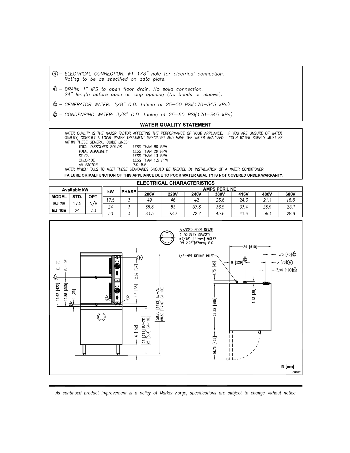
1.0 SERVICE CONNECTIONS
PART NUMBER 10223R1 4 2010-06-24

INSTALLATION AND OPERATION MANUAL AND PARTS LIST,
ELECTRIC CONVECTION STEAMER, MODELS EJ-7E, EJ-10E
2.0 INSTALLATION INSTRUCTIONS
This steamer was inspected before leaving the factory. The transportation company assumes
full responsibility for safe delivery upon acceptance of the shipment. Immediately after
unpacking the steamer, check for possible damage. If the steamer is found to be damaged
after unpacking, save the packaging material and contact the carrier within 15 days of delivery.
Prior to installation, verify that the electrical service agrees with the specifications on the
machine data plate which is located on the left side panel.
LOCATION
Allow space for plumbing and electrical connections. Allow adequate access for operating and
servicing the steamer, 36" (915 mm) at the front of the steamer and 15" (381 mm) above the
steamer.
LEVELLING AND ANCHORING
Using a spirit level or pan of water in the bottom of the steamer, adjust the levelling feet to level
the steamer front-to-back and side-to-side.
Mark hole locations on the floor through the anchoring holes provided in the flanged adjustable
feet. Remove the steamer and drill holes at marked locations on the floor. Insert proper
anchoring devices.
Set steamer back in proper position.
Install bolts through anchoring holes and into anchors to secure the steamer to the floor. Seal
bolts and flanged feet with Silastic.
After the drain is connected, check for level by pouring water onto the floor of the compartment.
All water should drain through the opening at the back of the compartment cavity.
ELECTRICAL CONNECTION
WARNING: Electrical and grounding connections must comply with
applicable portions of the national electrical code and/or other local
electrical codes.
PART NUMBER 10223R1 5 2010-06-24
INSTALLATION AND OPERATION MANUAL AND PARTS LIST,
ELECTRIC CONVECTION STEAMER, MODELS EJ-7E, EJ-10E
INSTALLATION INSTRUCTIONS (Continued)
WARNING: Disconnect the power supply to the appliance before
cleaning or servicing.
Make electrical connection through the 1-1/8" (29 mm) diameter hole provided using 3/4" (19
mm) trade size conduit. Refer to the wiring diagram located inside the right side panel. Use
90°C minimum insulated wire.
PLUMBING CONNECTIONS
WARNING: Plumbing connections must comply with applicable
sanitary, safety, and plumbing codes.
The water supply inlets are provided with 3/8" (10 mm) compression fittings for 3/8" O.D.
copper tubing. The water supply line pressure should be 25 - 50 psi (170 - 345 kPa) for each
line. The water supply to the generator tank is separate from the water supply to the cooling
system where steam is condensed before entering the drain line.
Install line strainers (not provided). A manual shutoff valve for each supply line must be
provided convenient to the steamer.
We recommend treated water feeding the boiler inlet supply, and untreated water feeding the
cooling system inlet. Hook-ups are labelled on the back of the steamer.
ADJUSTMENT FOR HIGH ALTITUDE LOCATIONS
The steamer has been factory set so that when it is ON, and during the READY phase, it will
maintain water temperature in the steam generator tank at approximately 205°F (96°C) (just
below water boiling point). However, for high altitude locations, an authorized service agency
must adjust the steamer to achieve this temperature.
ADJUSTMENT FOR DRAIN WATER TEMPERATURE
Cooling solenoid valves have been adjusted to yield drain temperatures of 140°F. This will vary
depending on install location water supply temperature and pressure. A qualified service
person should adjust the cooling solenoid valves should the drain temperature be other than
desired. Refer to Section 7.0 Service on page 20 for adjustment instructions.
PART NUMBER 10223R1 6 2010-06-24

INSTALLATION AND OPERATION MANUAL AND PARTS LIST,
ELECTRIC CONVECTION STEAMER, MODELS EJ-7E, EJ-10E
DRAIN CONNECTIONS
The drain connection must be 1" (25 mm)
IPS down, preferably with one or two
elbows only, maximum length 6 feet (1830
mm) and piped to an open gap type drain
(Figure 1). Drain pipe should be either iron
or copper. DO NOT use PVC pipe – PVC
pipe may lose its rigidity or glue may fail.
CAUTION: To avoid
injury or damage to the
steamer, do not connect
solidly to any drain
connection.
FIGURE 1
WATER QUALITY
The water supply connected to the steam generator should meet the following guidelines:
Failure to comply with water quality statement on page 4 may void the warranty.
Water supplies vary from one location to another. Other factors affecting steam generation are
iron content, chlorides, and dissolved gasses. A local water treatment specialist should be
consulted before installing any steam generating equipment.
Untreated water contains scale producing minerals which can precipitate onto the surfaces in
the boiler. Due to the temperatures in the boiler, the minerals can bake onto the surfaces and
components. This can result in early component failure and reduced product life.
Mineral scale on components causes several problems:
1. The surfaces of the heating devices become coated with scale, reducing the heat transfer
efficiency. This can produce hot spots on the heating elements and result in premature
failure.
PART NUMBER 10223R1 7 2010-06-24

INSTALLATION AND OPERATION MANUAL AND PARTS LIST,
ELECTRIC CONVECTION STEAMER, MODELS EJ-7E, EJ-10E
WATER QUALITY (Continued)
2. The water level probes become coated with scale. Scale will bridge across the probe
insulator from the metal extension which senses the water level in the boiler shell. Once
this scale becomes wet, the water level control is unable to maintain the proper water level
in the boiler. This situation may cause an electric heating element to fail if the element is
not adequately covered by water.
Strainers and filters will not remove minerals from the water.
Refer to REMOVAL OF LIME SCALE DEPOSITS, page 18.
VENT HOOD
Some local codes may require the steamer to be located under an exhaust hood. Information
on the construction and installation of ventilating hoods may be obtained from NFPA Standard
No. 96, Vapor Removal from Cooking Equipment, (latest edition).
PART NUMBER 10223R1 8 2010-06-24

INSTALLATION AND OPERATION MANUAL AND PARTS LIST,
ELECTRIC CONVECTION STEAMER, MODELS EJ-7E, EJ-10E
START-UP TEST
WARNING: The steamer and its parts are hot. Use care when
operating, cleaning or servicing the steamer. The cooking
compartment contains live steam. Stay clear while opening the
door.
Once the steamer is installed and all mechanical connections have been made, thoroughly test
the steamer before operation.
1. Check that proper water, drain, and electrical connections have been made.
2. Turn main power switch ON. After approximately 15 minutes, the READY light should come
on, indicating that the water temperature is 205°F (96°C).
3. When the READY light comes on, set the timer at 5 minutes. With door open, observe that
no steam is entering the compartment and the COOKING light is OFF.
4. Close compartment door. The COOKING light should now be lit and steam should be
heard entering the compartment after about 45 seconds (5 minutes if boiler is empty).
5. Check drain line to ensure that water from the cold water condenser is flowing through the
drain line.
6. Open compartment door and observe that steam supply to the chamber is cut off (READY
light should again come on and COOKING light goes off).
7. Close compartment door and let cooking cycle finish. When the timer returns to the “O”
position, a buzzer will sound, signalling the end of the cooking cycle. To silence the buzzer,
turn the dial timer to OFF.
8. Complete the above steps for each cooking compartment.
9. To shut the steamer down, turn the main power switch OFF and leave the compartment
doors slightly open to allow the inside to dry out.
PART NUMBER 10223R1 9 2010-06-24

INSTALLATION AND OPERATION MANUAL AND PARTS LIST,
ELECTRIC CONVECTION STEAMER, MODELS EJ-7E, EJ-10E
3.0 OPERATION INSTRUCTIONS
WARNING: An obstructed drain can cause personal injury or
property damage.
1. Ready Plot Light When lit, indicates steam generator
2. Cooking Pilot Light When lit, indicates that a cooking
3. Timed Cooking/Constant Cooking Mode Set the cooking time (0 to 60
4. Main Power Switch
ON The steam generator will
OFF The steam generator will drain. No
DELIME Closes the drain valve while CLR
has reached 200º Fahrenheit (93º
Celsius) and is ready for the cooking
cycle.
cycle is in progress.
minutes) - steam cooking will begin
after the door is closed. The
cooking cycle will be interrupted if
the door is opened during the
cooking cycle; resume cooking by
closing the door. Select “Constant
Steam” for continuous cooking.
automatically fill and begin heating
to the pre-set temperature for
standby. Red light will illuminate on
the main power switch.
lights.
liquid is being poured into the steam
generator during the Delime
procedure. Amber light will
illuminate on the main power switch.
5. Buzzer Signals end of cooking period (not
shown).
PART NUMBER 10223R1 10 2010-06-24

INSTALLATION AND OPERATION MANUAL AND PARTS LIST,
ELECTRIC CONVECTION STEAMER, MODELS EJ-7E, EJ-10E
3.0 OPERATION INSTRUCTIONS (Continued)
BEFORE FIRST USE
Clean the protective oils from all surfaces of the steamer. Use a non-corrosive, grease
dissolving commercial cleaner, following manufacturer’s directions. Rinse thoroughly and wipe
dry with a soft clean cloth.
PREHEAT
Turn the main power switch ON. When the READY light comes on, set the timer to 1 minute to
preheat the compartment. This should be done when the steamer is first used for the day or
whenever the chamber is cold. The door should be closed during the preheat cycle. The
COOKING light will be lit. When the buzzer sounds, set the timer to the OFF position. The
steamer is now ready to cook.
COOK
With compartment preheated and READY light ON, place pans of food into the compartment
and close the door.
Set timer to desired cooking time. (The cooking cycle may be interrupted at any time by
opening the door. To resume operation, close the door.) Steam will flow into the compartment
and the COOKING light will be lit.
At the end of the cooking cycle, the buzzer will sound, the COOKING light will go off and steam
supply to the compartment will cease. Turn the timer to the OFF position to silence the buzzer.
CONSTANT STEAM COOKING - This mode will give continuous steam to the cooking
chamber until the operator turns power OFF to the steamer. .
When cooking is complete, or not in use, the constant steam cooking feature should be shut
off. This prevents the boiler from running unnecessarily. This will help conserve water, and will
reduce boiler maintenance.
SHUTDOWN
Turn main power switch OFF. The boiler will automatically blow down. Leave the compartment
door open to allow the inside to dry out. For an extended shutdown, turn the main power switch
OFF; turn power and water supply OFF.
Drain the boiler after each day’s use to flush out minerals and minimize scale build-up. The
boiler drains automatically for approximately 4 - 6 minutes after the main power switch is turned
off.
PART NUMBER 10223R1 11 2010-06-24

INSTALLATION AND OPERATION MANUAL AND PARTS LIST,
ELECTRIC CONVECTION STEAMER, MODELS EJ-7E, EJ-10E
COOKING HINTS
Your steamer efficiently cooks vegetables or other foods for immediate serving. Steam cooking
should be carefully time controlled. Keep hot food holding-time to a minimum to produce the
most appetizing results. Prepare small batches, cook only enough to start serving, then cook
additional amounts to meet demand.
Preparation
Prepare vegetables, fruits, meats, seafood, and poultry normally by cleaning, separating,
cutting, removing stems, etc. Cook root vegetables in a perforated pan. Other vegetables may
be cooked in a perforated pan unless juices are being saved. Liquids can be collected in a
solid pan placed under a perforated pan.
Perforated pans are used for frankfurters, wieners, and similar items when juices do not need to
be preserved. Solid pans are good for cooking puddings, rice and hot breakfast cereals.
Vegetables and fruits are cooked in solid pans in their own juice. Meats and poultry are cooked
in solid pans to preserve their juice or return broth.
Canned foods can be heated in their opened cans (cans placed in solid pans), or the contents
may be poured into solid pans. DO NOT place unopened cans in the steamer.
Frozen Food Items
Separate frozen foods into smaller pieces to allow more efficient cooking.
Use a pan cover for precooked frozen dishes that cannot be cooked in the covered containers
in which they are packed if they require more than 15 minutes of cooking time. When a cover
is used, approximately one-third additional cooking time is necessary. Cooking time for frozen
foods depends on the amount of defrosting required. If time permits, allow frozen foods to
partially thaw overnight in a refrigerator. This will reduce their cooking time.
PART NUMBER 10223R1 12 2010-06-24
 Loading...