

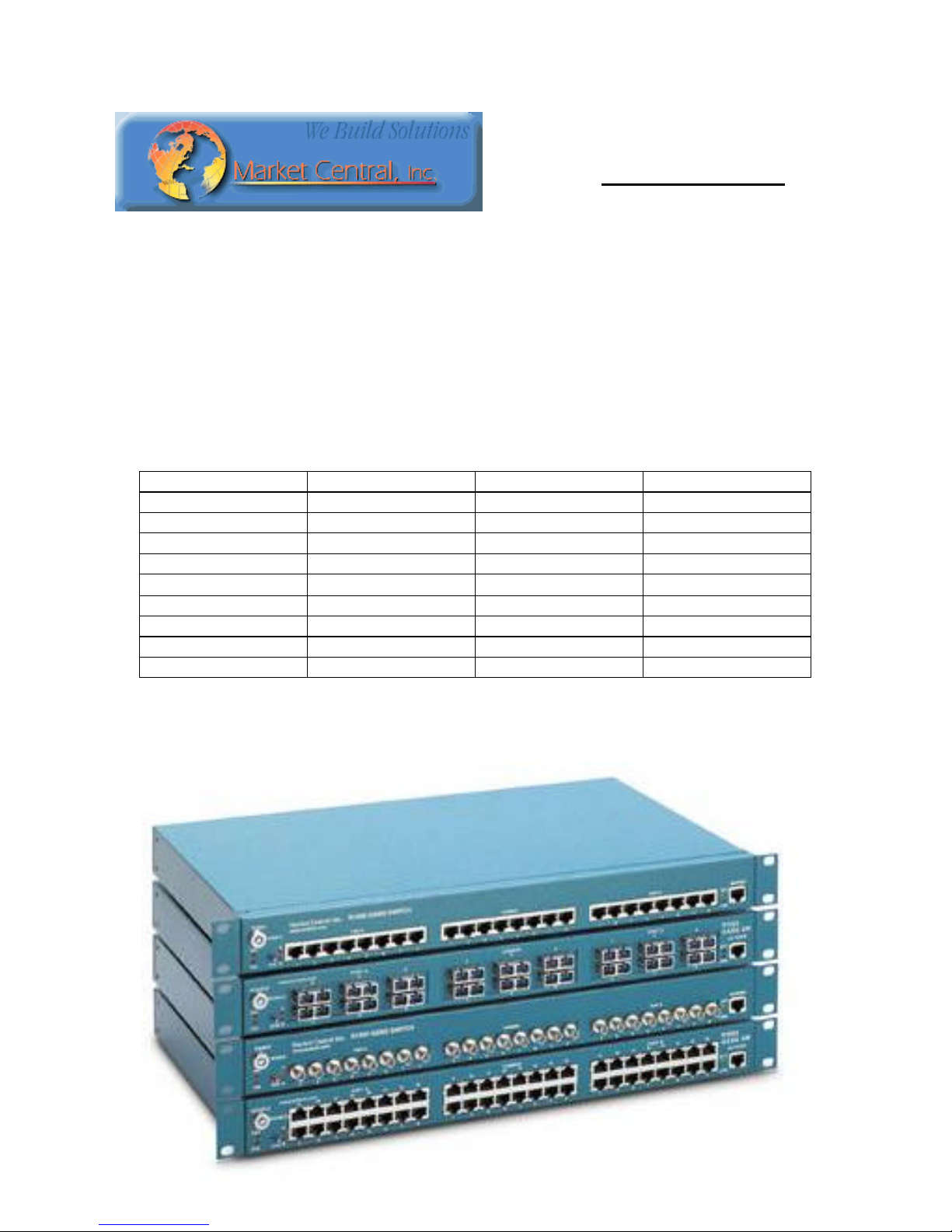
Market Central R1000-NAC-8, R1000-NBS-4F, R1000-NBS-6F, R1000-NBS-8, R1000-NBS-6FR User Manual
...Page 1
Market Central
412.494.2800
CAG
E 1BGJ7
www.secureswitch.com
500 Business Center Drive Pittsburgh, PA 15205 USA
R1000 NBS - Network Backup Switch
R1000 NAC – Network Access Controller
SWITCHING SYSTEM
USERS MANUAL
Jan 2008
Part Numbers
R1000-NAC-8 5101000 R1000-NAC-4FR (ST)
R1000-NAC-16 5101001 R1000-NAC-6FR (ST)
R1000-NAC-8R 5101002 R1000-NBS-4F (ST) 5101030
R1000-NAC-16R 5101003 R1000-NBS-6F (ST) 5101031
R1000-NBS-8 5101020 R1000-NBS-4FR (ST)
R1000-NBS-16 5101021 R1000-NBS-6FR (ST)
R1000-NBS-8R 5101022 R1000-NBS-4F (SC) 5101034
R1000-NBS-16R 5101023 R1000-NBS-6F (SC) 5101035
R1000-NAC-4F (ST) 5101010 R1000-NBS-4FR (SC)
R1000-NAC-6F (ST) 5101011 R1000-NBS-6FR (SC)
* R designates SNMP capable models (i.e. R1000-NBS-8R), for “remote accessible via Ethernet”.
5101012
5101013
5101032
5101033
5101036
5101037
Market Central Inc., 500 Business Center Drive, Pittsburgh, PA 15205
Phone: (412) 494-2800, Fax: (412) 494-5550, www.mctech.com CAGE Code 1BGJ7
© Copyright 2003. Market Central, Inc. All rights Reserved.
Page 2

Market Central, Inc.
Contents
Chapter Page
1. Specifications 2
2. Introduction 3
3. Configuration 3
4. Installation 3
5. Operation 4
6. Network Setup 6
7. Console Commands 7
8. Web Interface 11
9. SNMP MIB Path Summary 13
1. Specifications
Connectors:
A/B Switches: Shielded RJ45 – 16, 24, 32, or 48 depending on model and size
Fiber optic ST or SC – 4 or 6 duplex connectors depending on model and size
Ethernet: Shielded RJ45 – active only in network manageable models
Serial Control: Female DB9
Power: Two-Position DC Power Entry – 2 provided for redundancy
Indicators:
Power supply LEDs: (2) power supply input 1, power supply input 2
Switch position LEDs: (2) all ports position A, all ports position B
Network status LEDS: (2) link, activity (active only in network manageable models)
Switches:
A/B Gang switch: (1) momentary toggle switch
Gang Switch enable: (1) key-lock switch
Power:
9-12 VDC, 100 mA nominal (350mA nominal on network manageable models)
RJ45 8 port, additional 187 mA while switching
RJ45 16 port, additional 374 mA while switching
Fiber Optic 4 port, additional 320 mA while switching
Fiber Optic 6 port, additional 480 mA while switching
Dual inputs for redundancy
Physical:
1.75”(H) X 17.25”(W) X 10.5”(D) desktop chassis, steel
Mounting brackets provided for 1U, 19” rack mount configuration
5 lbs, excluding power supply
MTBF:
100,000 hours
Altitude Tolerance:
10,000 ft. (3048 m)
Temperature Tolerance:
Operating: 32° to 104° F (0° to 40° C)
Storage: -4° to 158° F (-20° to 70° C)
Humidity Tolerance:
Up to 95% non-condensing
R1000 NBS/NAC Page 2 of 16
Page 3

Market Central, Inc.
2. Introduction
The R1000 Network Backup Switch and Network Access Controller connect port A or port B to COMMON,
through latching relays (in the case of the R1000-NAC models, the connection is more appropriately designated ON
or OFF, as they are 2 port switches, COMMON to port B (ON) Common to port A (OFF). Since the relays are
latching, the state of connections will be maintained with power off.
For RJ45 models, pins 1, 2, 3 and 6 are switched, which are the standard 10/100base-T Ethernet signal locations on
an RJ45 connector. While the R1000 is primarily intended to switch Ethernet, it can be used for any electronic
signal switching, if the signals are passed through the supported pins. The relays are transparent to data rates, signal
levels and format. The RJ45 models are available in 8 and 16 port versions.
Fiber optic models are also latching, and use precision optical mirror mechanisms to switch connections and are thus
completely transparent to rates, protocols, and wavelengths. The fiber optic models are available in 4 and 6 port, ST
and SC duplex versions.
Manual gang control of all ports is available through a momentary toggle switch on the front of the unit, enabled by
a removable key lock. Serial RS232 control can gang or individually switch ports, as well as monitor switch status.
An Ethernet port (10base-T) on network manageable models allows remote control and monitoring using TCP/IP.
The R1000 models are housed in a steel desktop chassis, with provisions for 19” rack mount (brackets supplied).
3. Configuration
There are no user configurable settings on the R1000 models for basic operation. There are some parameters related
to TCP/IP operations which are accessed through the serial RS232 port, which are required to communicate to the
unit over Ethernet. These settings are described later in this manual.
The internal jumpers and DIP switches inside the R1000 have been pre-configured at the factory and should not be
changed from their default settings. They are shown here for reference only.
jumper W1 1-2 position = no SNMP module, serial RS232 only
2-3 position = SNMP module installed, Ethernet & serial RS232
jumper W2 1-2 position = no SNMP module, serial RS232 only
2-3 position = SNMP module installed, Ethernet & serial RS232
DIP SW1 positions 1 & 2 OFF, and positions 3 & 4 ON to limit to < 4 port operation
positions 1 & 3 OFF, and positions 2 & 4 ON to limit to < 6 port operation
positions 1, 2 & 3 OFF, and position 4 ON to limit to < 8 port operation
positions 1 – 4 all OFF to limit to < 16 port operation
position 5 OFF = SNMP module installed, position 5 ON = RS232 only
position 6 OFF = non-latching fiber optic modules, position 6 ON = latching foms or relays
position 7 OFF = non-latching relays, position 7 ON = latching relays
position 8 OFF (reserved for future use)
DIP SW2 positions 1-8 ON (reserved for future use)
4. Installation
1. Find a location suitable for installing the R1000 chassis, with access to AC power outlets and the
connections you intend to switch through the unit.
2. If you intend to use serial control, connect a serial cable to the DB9 RS232 console port, the baud rate is
fixed at 9600 baud, no parity, 8 data bits, and 1 stop. See figure 1 for connector signal assignment.
R1000 NBS/NAC Page 3 of 16
Page 4

Market Central, Inc.
3. Connect a 12VDC power supply to either power supply connector. If you are using redundant power
supplies, connect one to each power supply connector. The indicators, PS1 and PS2, on the front of the
unit will indicate a power supply energized.
4. Connect RJ45 or fiber optic cables between the R1000 unit and your devices to switch. The R1000 NBS
connects the COMMON ports to either A ports or B ports. For NAC models, selecting port A (OFF)
disconnects COMMON ports from B ports, selecting port B (ON) connects COMMON ports to B ports.
5. The R1000 switches are completely bidirectional, and have no preference to signal direction. Note that the
switch provides straight pass thru connections. If your application requires a cross-over cable, use only 1
cross-over cable in that path. Use a straight through cable on the other side of the switch.
6. Apply AC power to (each) power supply. The appropriate power supply status indicators (PS1 and/or PS2)
will light. The switch position indicators (A and B) on the front of the unit may or may not light depending
on the position of the switches. Indicator A lights when all switches are in position A, and likewise for
indicator B.
If you are connecting the R1000 (network manageable model) to an Ethernet network, you must first set some
TCP/IP related parameters using the serial port. You should set these parameters before attaching a cable to the
NETWORK port, as the default parameters may not work or could interfere with your network. See section 5.3 for
more information regarding TCP/IP setup.
5. Operation
When power is applied to the R1000 unit, the appropriate power supply status indicators (PS1 and/or PS2) will light.
The switch position indicators (A and B) on the front of the unit may or may not light depending on the position of
the switches. Indicator A lights when all switches are in position A, and likewise for indicator B. If some switches
are in position A and some in position B then neither light will be on.
For RJ45 models, The R1000 NBS connects the COMMON ports to either A ports or B ports. For NAC models,
selecting port A (OFF) disconnects COMMON ports from B ports, selecting port B (ON) connects COMMON ports
to B ports. Ports 2-N, depending on the model size, is similarly switched.
For fiber optic models, the switching uses duplex connections per channel. For ST models, the two connectors
labeled 1 and 2 form the channel 1 path, connectors 3 & 4 form the channel 2 path, and so on. The fiber paths are
bidirectional, with COMMON port 1 switched to A port 1 or B port 1 (or COMMON port 1 to B port 1/open), etc.
Note that if COMMON port 1 is used as an input, for example, A/B port 1 is then the switched output. For SC
models, the COMMON duplex connector labeled 1 is switched to either A port 1 or B port 1 (R1000-NAC models,
selecting port A (OFF) disconnects COMMON ports from B ports, selecting port B (ON) connects COMMON ports
to B ports. Ports 2-N, depending on the model size, is similarly switched. All R1000 connections are straight
through. Be sure to connect the fiber optic RX/TX appropriately for your application.
5.1 Manual Switching
All R1000 models can be switched (all ports simultaneously) from a manual switch located on the front of the unit.
This switching action is enabled by the front panel key switch, which must be in the position labeled ENABLE for
manual switching to occur. When “gang” switching all ports, the switch position indicator will light to the
appropriate state (A or B).
5.2 Serial RS232 Switching
All R1000 models can be switched using commands over a serial communications line. The parameters of the
console port are fixed at 9600 baud, no parity, 8 data bits, and 1 stop (commonly abbreviated as 9600, N, 8, 1).
When the R1000 powers up, it will send a sign-on message followed by a prompt character “>” to your serial
device. After each command, and any associated response from the unit, it will again issue a prompt character. For
systems where the console port is being commanded by software, the software should wait for this prompt character
R1000 NBS/NAC Page 4 of 16
Page 5

Market Central, Inc.
before sending each and every command to the R1000.
It is possible to switch any or all of the ports to either A or B from serial commands. It is also possible to query the
position of any or all of the ports from serial commands. Serial command functionality is NOT affected by the
position of the front panel key switch. See section 7 for a complete list of commands for the network manageable
models.
RS232 versions only
The following commands are available from the console prompt of the unit. All commands are case insensitive,
although several variable parameters are case sensitive (read/write community names and web password). GET,
SET and PORT can all be abbreviated by the first letter of the command. This allows shorthand entry of switching
commands.
HELP Displays a list of commands. An example output is shown here.
>help
help
R1000 Rev. D
Commands:
get all
get port y (y = port, 1 to 16)
set all X (X = A or B)
set port y X (y = port, 1 to 16, X = A or B)
help or ? (displays this list)
>
get all - shows the status of all ports ex. AAAAAAAA
get port y – shows the status of a specific port ex. port 1 A
set all X – sets all ports to either A or B
set port y x – sets a specific port to either A or B ex. set port 4 A
help or ? shows a list of commands available from the console prompt of the unit
5.3 Ethernet Switching (SNMP network manageable units only)
In order to use the Ethernet Network port you must set the IPADDRESS and SUBNETMASK and GATEWAY
address of the R1000 before connecting to your network. See section 6 for more details
The R1000 can be switched using SNMP commands over a TCP/IP Ethernet network. See the MIB path summary
in the appendix for a list of SNMP variables and their functions. The R1000 also supports telnet access, and can be
controlled via a telnet session using the same commands as used by the RS232 serial interface. The R1000 also
includes a built in http server that allows all of the commands available via the RS232 serial port to be accessed via
a web browser interface. See section 8 for more details about this feature.
The NETWORK port is 10base-T only. There are two status indicators which function as follows. The LINK led is
on whenever the R1000 network interface is ready for communication. This should happen very shortly after power
on, and should go out if there is some problem with the interface detected by the unit. Note that it does not indicate
that a valid network connection is made. The ACT led will blink whenever the R1000 receives a command from the
network interface. Note that only access to variables on the ‘private’ branch will trigger the ACT led (OID
1.3.6.1.4…). In addition the ACT led will blink when a switching command is issued via the serial port.
After setting up the system and powering up for the first time (see Network Setup section), you may need to change
other parameters for your application. These parameters are stored in non-volatile memory, although they are
immediately active when a change is made they will not become permanent until the SAVE command, followed by
the RESET command are performed.
R1000 NBS/NAC Page 5 of 16
Page 6

Market Central, Inc.
6. Network Setup (SNMP network manageable units only)
To perform initial setup of the unit you will need a serial terminal capable of 9600 baud, no parity, 8 data bits, and 1
stop bit. Connect this terminal to the DB9 console connector as follows (Use a straight thru M/F cable to connect to
an IBM PC standard DB9 serial port).
Table 6.1 – DB9 Pin Assignment
DB9 SIGNAL DIRECTION
2 RECEIVED DATA TO TERMINAL
3 TRANSMITTED DATA FROM TERMINAL
5 GROUND
Apply power to the system.
After this process is complete you will see a sign-on message displayed on the serial console, i.e.
At this point the console is ready for some low level configurations necessary before you will be able to
communicate with the unit using TCP/IP. You will need to enter an IP address and subnet mask, as well as read and
write SNMP community names if using SNMP, or a web password for browser access. These parameters will be
saved into non-volatile memory, and the system will be reset to allow it to reconfigure with the new settings. Any
time one or more of these parameters is changed; they must be saved followed by a system reset in order for the
changes to become permanent. The following shows a typical setup session. Change the entered parameters to suit
your application requirements. All the console level commands available are described in detail in section 7.
After the system reinitializes, you will again be greeted by the sign-on message as before. At this time you can
connect a 10 base-T CAT5 cable to the network port on the R1000 and an available port on your hub. The unit will
respond to SNMP and HTTP messages at the assigned IP address. See the MIB Path Summary for a list of SNMP
variables and their functions.
R1000 Network Agent Version 2.6c Jan 2009
Copyright (C) 2006 Market Central, Inc.
All rights reserved
www.mctech.com
System starting ...
console ready.
>
>set ipaddress 192.168.1.200
OK
>set subnetmask 255.255.255.0
OK
>set readcommunityname public
OK
>set writecommunityname private
OK
>save
OK
>reset
restarting …
R1000 NBS/NAC Page 6 of 16
Page 7

Market Central, Inc.
7. Console Commands (SNMP network manageable units only)
The following commands are available from the console prompt of the unit. All commands are case insensitive,
although several variable parameters are case sensitive (read/write community names and web password). GET,
SET, SYSTEM, and PORT can all be abbreviated by the first letter of the command. This allows shorthand entry of
switching commands.
GET ALL
Displays all parameters and settings. An example output is shown here.
GET VERSION
Displays the software revision of the system.
GET SYSTEM
Displays the system status. This is the same as the status returned by the SNMP variable r1000GangPort. It will
report “A” if any switches are in position A, and “B” if all switches are in position B. This is meaningful only when
using system level switching commands.
SET SYSTEM A[B]
Sets the system to position A or B.
GET RACK
System Status: B
IP Address: 192.168.1.200
Subnet Mask: 255.255.255.0
Gateway IP Address: 192.168.1.1
Web Enable: Enabled
Web Password: mctech
Web Timeout: 300
Web Port: 80
Telnet Enabled: Enabled
Telnet Password: dataman
Telnet Timeout: 80
Telnet Port: 23
Read Community Name: public
Write Community Name: private
Authentication Trap: Disabled
R1000: 2.6c Jan 2009, R1000 Rev.D
SNMP Manager Table:
1: 192.168.1.113
2: 192.168.1.115
R1000: 2.6c Apr, R1000 Rev. D
System Status: A
• Displays status of unit. This is the same as the status returned by the SNMP variable r1000Channels. It
displays a 16 character string showing the status of each switch. Models with less than 16 ports will
display X in place of A or B when querying status.
Rack Status: AAABAABAAAABAAAA
R1000 NBS/NAC Page 7 of 16
Page 8

Market Central, Inc.
GET PORT N
Displays the status of switch N (1-16). The response will be “A” or “B”.
SET PORT N A[B]
Sets the addressed switch N (1-16) to position A or B.
SET IPADDRESS X.X.X.X
GET IPADDRESS
Set or display the current IP address of the network module. Any change will not become permanent until a SAVE
and RESET operation sequence is performed.
SET SUBNETMASK X.X.X.X
GET SUBNETMASK
Set or display the current subnet mask of the network module. Any change will not become permanent until a
SAVE and RESET operation sequence is performed.
SET GATEWAY X.X.X.X
GET GATEWAY
Set or display the current gateway IP address of the network module Any change will not become permanent until a
SAVE and RESET operation sequence is performed.
SET READCOMMUNITYNAME string
GET READCOMMUNITYNAME
SET READCOMMUNITYNAME string
GET READCOMMUNITYNAME
Set or display the current read or write community name as specified. Note that in general these are case sensitive
fields. Any change will not become permanent until a SAVE and RESET operation sequence is performed.
SET WEBENABLE ON[OFF]
GET WEBENABLE
Set or display the current state of web based access. The network module will not accept any HTTP requests when
web enable is off. Any change will not become permanent until a SAVE and RESET operation sequence is
performed.
SET WEBPASSWORD string
GET WEBPASSWORD
Set or display the current web password. Note that this is a case sensitive field. Any change will not become
permanent until a SAVE and RESET operation sequence is performed.
SET WEBTIMEOUT seconds
GET WEBTIMEOUT
Set or display the current web timeout in seconds. After a period of inactivity of this many seconds, the network
module will request a login. Note that the web timeout cannot be disabled any change will not become permanent
until a SAVE and RESET operation sequence is performed.
Port 4: B
R1000 NBS/NAC Page 8 of 16
Page 9

Market Central, Inc.
SET TELNETENABLE ON[OFF]
GET TELNETENABLE
Set or display the current state of telnet based access. The network module will not accept any telnet requests when
telnet enable is off. Any change will not become permanent until a SAVE and RESET operation sequence is
performed.
SET TELNETPASSWORD string
GET TELNETPASSWORD
Set or display the current telnet password. Note that this is a case sensitive field. Any change will not become
permanent until a SAVE and RESET operation sequence is performed.
SET TELNETTIMEOUT seconds
GET TELNETTIMEOUT
Set or display the current telnet timeout in seconds. After a period of inactivity of this many seconds, the network
module will disconnect any current telnet session. Note that the telnet timeout cannot be disabled, it can however,
be set arbitrarily large. Any change will not become permanent until a SAVE and RESET operation sequence is
performed.
SET TELNETPORT N
GET TELNETPORT
Set or display the current telnet port number. Changing the telnet port number from the default can be used to
provide an additional level of security. Any change will not become permanent until a SAVE and RESET operation
sequence is performed.
SET AUTHENTICATIONTRAP ON[OFF]
GET AUTHENTICATIONTRAP
Set or display the current state of authentication error traps. Authentication traps will be generated when this
parameter is set to ON, and not when OFF. Note that this setting only affects the trap generation, and not how the
network module handles an authentication failure. An authentication failure generally means that an SNMP access
was attempted with an incorrect community name. Any change will not become permanent until a SAVE and
RESET operation sequence is performed.
SET MANAGER N X.X.X.X
Set SNMP manager N (1-16) IP address.
Up to 16 SNMP MANAGER IP addresses can be entered for destinations of trap messages. Trap messages will be
sent to all enabled MANAGER IP addresses. To remove an entry from the list, set the IP address to 0.0.0.0.
Any change will not become permanent until a SAVE and RESET operation sequence is performed.
GET MANAGER N
Display SNMP manager N (1-16) IP address.
SNMP Manager Table:
1: 192.168.1.113
2: 192.168.1.115
3: 192.168.1.149
4: 192.168.1.100
R1000 NBS/NAC Page 9 of 16
Page 10

Market Central, Inc.
GET MANAGER
Display all SNMP manager IP addresses.
SAVE
Save settings for next startup. All settings are stored in NV memory and restored upon power on. Any change will
not become permanent until a SAVE and RESET operation sequence is performed.
RESET
Causes a network system reboot and reloads all parameters from stored settings.
HELP
Displays a list of commands.
>help
Notes:
R1000 CONSOLE COMMANDS:
GET ALL (display all parameters)
GET VERSION (display software versions)
GET[SET] SYSTEM [A/B] (control all system ports)
GET RACK (display all ports)
GET[SET] PORT N [A/B] (control single port)
GET[SET] IPADDRESS [X.X.X.X]
GET[SET] SUBNETMASK [X.X.X.X]
GET[SET] GATEWAY [X.X.X.X]
GET[SET] READCOMMUNITYNAME [string]
GET[SET] WRITECOMMUNITYNAME [string]
GET[SET] WEBENABLE [ON/OFF]
GET[SET] WEBPASSWORD [string]
GET[SET] WEBTIMEOUT [N] (seconds)
GET[SET] WEBPORT [N]
GET[SET] TELNETENABLE: [on/off]
GET[SET] TELNETPASSWORD [string]
GET[SET] TELNETTIMEOUT N: (seconds)
GET[SET] TELNETPORT (N)
GET[SET] AUTHENTICATIONTRAP [ON/OFF]
GET[SET] MANAGER N [X.X.X.X] (0.0.0.0 to disable an entry)
GET MANAGER (display all SNMP managers)
SAVE save settings for next startup
RESET restart (use after SAVE)
• Commands can be entered in upper or lower case.
• Models with less than 16 ports will display X in place of A or B when querying status.
• All commands should be terminated with a carriage return (ASCII 13) or (hex 0x0D).
• Set/get all and set/get port commands can be abbreviated using just first letters, i.e. “g a” for “get all” or “s
p 4 a” for “set port 4 a”.
• * Remote (network) models use “get system” and “set system X” for “get/set all” commands. The
command “get all” returns all parameter settings (to be compatible with R5000 and R6000 command
structures).
R1000 NBS/NAC Page 10 of 16
Page 11

Market Central, Inc.
8. Web Interface (SNMP capable models only)
The network module provides access to console commands through a web browser interface. When enabled (see
SET WEBENABLE command) accessing the default page on the modules IP address (index.html) will present the
following page (or similar).
Note: If using a pop up blocker on your web browser, be sure to allow pop ups from the IP address of the R1000,
otherwise you cold experience trouble receiving a response through the interface.
Web Interface Version 1.0
Copyright (c) 2003, Market Central Inc.
All rights reserved.
www.mctech.com
Please logon:
Password:
Submit
After successfully entering the correct web password (see SET WEBPASSWORD command) you will get the
following page (or similar).
Figure 8.1 Logon Screen
Web Interface Version 1.0
Copyright (c) 2003, Market Central Inc.
All rights reserved.
www.mctech.com
Command console:
Enter new command:
Send Command Logoff
Figure 8.2 Initial Command Screen
At this point you may enter any valid command into the text box and click “Send Command” to execute. The
following is an example result of the GET ALL command.
Web Interface Version 1.0
Copyright (c) 2003, Market Central Inc.
All rights reserved.
www.mctech.com
Command console:
Output from last command...
System Status: B
IP Address: 192.168.1.30
R1000 NBS/NAC Page 11 of 16
Page 12

Subnet Mask: 255.255.255.0
Gateway IP Address: 192.168.1.1
Web Enable: Enabled
Web Password: mctech
Web Timeout: 300
Web Port: 80
Telnet Enable: Enabled
Telnet Password: dataman
Telnet Timeout: 80
Telnet Port: 23
Read Community Name: public
Write Community Name: private
Authentication Trap: Disabled
R1000: 2.6c Jan 2009, R1000 Rev. D
SNMP Managers:
Enter new command:
Market Central, Inc.
Send Command Logoff
Figure 8.3 Example Command Results Screen
The Ethernet version of Controller Card will only allow 1 telnet or web access session. To free up a session without
waiting for the web timeout, click “Logoff”. For this reason, the web timeout should be set to a workable time.
Resetting the unit will clear the current web session.
R1000 NBS/NAC Page 12 of 16
Page 13

Market Central, Inc.
9. SNMP MIB Path Summary
NOTE: The MIB contains definitions that do not apply to every product in the R1000 family.
[internet] – 1.3.6.1
[private] – 1.3.6.1.4
[enterprises] – 1.3.6.1.4.1
[mctech] – 1.3.6.1.4.1.9477
[mctech] – 1.3.6.1.4.1.9477
Market Central, Inc. private enterprise number
[mcAgent] – 1.3.6.1.4.1.9477.1
Market Central, Inc. SNMP Agent
The following is a list of the A/B Switch System SNMP variables corresponding to:
R1000 NBS/NAC Switch
[r1000] – 1.3.6.1.4.1.9477.1.6
R1000 Switch
[r1000GangControl] – 1.3.6.1.4.1.9477.1.6.1
[r1000KeyStat] – 1.3.6.1.4.1.9477.1.6.2
[r1000PowerStat] – 1.3.6.1.4.1.9477.1.6.3
[r1000SoftwareVersion] – 1.3.6.1.4.1.9477.1.6.4
[r1000Name] – 1.3.6.1.4.1.9477.1.6.5
[r1000Channels] – 1.3.6.1.4.1.9477.1.6.6
[r1000ChannelTable] – 1.3.6.1.4.1.9477.1.6.7
[r1000ChannelIndex] – 1.3.6.1.4.1.9477.1.6.7.1.1. ChannelIndex
[r1000ChannelControl] – 1.3.6.1.4.1.9477.1.6.7.1.2. ChannelIndex
[r1000ChannelName] – 1.3.6.1.4.1.9477.1.6.7.1.3. ChannelIndex
[mcIpRequester] – 1.3.6.1.4.1.9477.2
Traps generated by the system
coldStart generic trap 0
authenticationFailure generic trap 4
r1000KeyLockChange Specific trap 1
r1000GangswitchChange Specific trap 2
r1000SwitchPortChange Specific trap 4
r1000PowerStatChange Specific trap 7
R1000 NBS/NAC Page 13 of 16
Page 14

Market Central, Inc.
R1000 Switch SNMP Variable Definitions:
[r1000GangControl] – 1.3.6.1.4.1.9477.1.6.1
R1000 Switch gang control. This variable is used to control all channels in a unit. A unit may
contain 4, 6, 8, or 16 channels depending on model. On a “GET” of this variable, the unit will
respond as follows. If any of the channels in the unit are at position A, the status will be A. If all
of the channels in the unit are at position B, the status will be B.
[r1000KeyStat] – 1.3.6.1.4.1.9477.1.6.2
R1000 Key-Lock Switch Status. This is a read only variable. This variable can be used to
determine if the Key-Lock Switch is in the OFF or ON position.
[r1000PowerStat] – 1.3.6.1.4.1.9477.1.6.3
R1000 Power Status. This is a read only variable. If power is applied to both power entry
connectors, the Power Status will report “TwoSupplies”. If power is applied to only one of the
power entry connectors, the Power Status will report “One Supply Down”.
[r1000SoftwareVersion] – 1.3.6.1.4.1.9477.1.6.4
R1000 Software Version. This is a read only variable, and is limited to a maximum of 14
characters.
[r1000Name] – 1.3.6.1.4.1.9477.1.6.5
R1000 Identification String. The string is limited to a maximum of 14 characters.
[r1000Channels] – 1.3.6.1.4.1.9477.1.6.6
R1000 channel status, One character for (up to) sixteen channels in the unit. Channels which
are not used will be represented by an X character. This is a READ ONLY variable.
[r1000ChannelTable] – 1.3.6.1.4.1.9477.1.6.7
R1000 channel variable table. This variable is not directly accessible.
[r1000ChannelIndex] – 1.3.6.1.4.1.9477.1.6.7.1.1. ChannelIndex
R1000 channel number.
[r1000ChannelControl] – 1.3.6.1.4.1.9477.1.6.7.1.2. ChannelIndex
R1000 channel control. This variable is used to control the addressed channel.
NBS version - When set to A, the switch will connect channel A to C. When set to B, the switch
will connect channel B to C.
NAC version- A is the off position, B to common is on
[r1000ChannelName] – 1.3.6.1.4.1.9477.1.6.7.1.3. ChannelIndex
R1000 channel Identification String. The string is limited to a maximum of 14 characters.
[mcIpRequester] – 1.3.6.1.4.1.9477.2
The IP address of the remote entity that last accessed branch 1.3.6.1.4.1.9477.1. This variable
can be used to identify the last IP address to access any mcAgent variable. It is returned in the
authenticationFailure message.
R1000 NBS/NAC Page 14 of 16
Page 15

Market Central, Inc.
R1000 Switch System SNMP Trap Definitions:
All traps carry the sysObjectId (1.3.6.1.2.1.1.2) variable, whose value is 1.3.6.1.4.1.9477.1.
coldStart – generic trap 0
This trap is sent during a power on initialization and reboot of the SNMP controller. It carries the
sysDescr variable (1.3.6.1.2.1.1.1).
authenticationFailure – generic trap 4
This trap is sent as a result of an authentication failure in processing an SNMP request.
Generally an authentication failure occurs as a result of an SNMP request with an invalid
community name. It carries the mcIpRequester variable.
r1000KeyLockChange - Specific trap 1
This trap is sent any time the keylock changes state, It carries the r1000KeyStat variable.
r1000GangswitchChange - Specific trap 2
This trap is sent when a system level switch occurs. It carries the r1000 GangControl variable.
r1000SwitchPortChange - Specific trap 4
This trap is sent when a single port is switched. It carries the r1000. It carries the r1000 channel
control variable.
r1000PowerStatChange - Specific trap 7
This trap is sent whenever power is connected or removed from either power connection. It
carries the r1000 power Stat variable.
R1000 NBS/NAC Page 15 of 16
Page 16

Market Central, Inc.
MARKET CENTRAL, INC.
WARRANTY AND LIMITATION OF LIABILITY
Market Central, Inc. (“Market Central”) warrants that the products manufactured and sold by
it or by one of its authorized resellers will, when sold, be free of defects in workmanship or material
under normal service and use. Products which have been changed or altered in any manner from
their original design, or which are improperly or defectively installed, serviced or used, are not
covered by this warranty. If any failure to conform to this warranty becomes apparent during a
period of one year after date of sale, Market Central shall, upon prompt, written notice and
compliance by the customer with such instructions as it shall give with respect to the return of
defective products or parts, correct such non-conformity by repair or replacement of the defective
part of parts. Correction in the manner provided above shall constitute a complete fulfillment of all
obligations and liabilities of Market Central with respect to the quality of said products. THE
FOREGOING WARRANTY IS EXCLUSIVE AND IN LIEU OF ALL OTHER WARRANTIES OF
QUALITY, WHETHER WRITTEN, ORAL OR IMPLIED, INCLUDING, WITHOUT
LIMITATION, ANY WARRANTY OF MERCHANTABILITY OR FITNESS FOR PURPOSE.
THIS WARRANTY AND THE OBLIGATIONS AND LIABILITIES OF MARKET
CENTRAL HEREUNDER ARE EXCLUSIVE AND IN LIEU OF AND BUYER HEREBY
WAIVES ALL OTHER REMEDIES, WARRANTIES, GUARANTIES OR LIABILITIES,
EXPRESS OR IMPLIED, ARISING BY LAW OR OTHERWISE (INCLUDING WITHOUT
LIMITATION ANY OBLIGATIONS OF MARKET CENTRAL WITH RESPECT TO FITNESS
FOR PURPOSE, MERCHANTABILITY AND INDIRECT, SPECIAL OR CONSEQUENTIAL
DAMAGES OR LOST PROFITS) OR WHETHER OR NOR OCCASIONED BY MARKET
CENTRAL’S NEGLIGENCE. THIS WARRANTY SHALL NOT BE EXTENDED, ALTERED OR
VARIED EXCEPT BY A WRITTEN INSTRUMENT SIGNED BY A DULY AUTHORIZED
OFFICER OF MARKET CENTRAL.
Federal Communications Commission (FCC) Statement
This equipment generates, uses, and can radiate radio frequency energy and if not
installed and used in accordance with the instruction manual, may cause interference to
radio communications. It has been tested and found to comply with the limits for a Class
A computing device in accordance with the specifications in Subpart J of Part 15 of FCC
rules, which are designed to provide reasonable protection against such interference when
the equipment is operated in a commercial environment. Operation of this equipment in
a residential area is likely to cause interference, in which case the user at his own expense
will be required to take whatever measures may be required to correct the interference.
Copyright© 2010. Market Central, Inc. All rights Reserved.
Market Central® is a registered trademark of Market Central, Inc. All rights reserved.
R1000 NBS/NAC Page 16 of 16
 Loading...