

Page 1
OWNER’S MANUAL
v_01_march_2017
Page 2

MARK
VISION
A WORD FROM MARCO DE VIRGILIIS
Thank you for choosing a Markaudio product!
Markaudio is a division of Mark World dedicated to
pro audio sound reinforcement.
Building on the top-level reputation built up over
many years by our industry-leading brands Markbass
and DV Mark , Markaudio boasts the same high level
of innovation and engineering.
The result is groundbreaking sound quality, impressive
power, and innovative design.
Hope you will enjoy your new Markaudio P.A. system,
and we invite you to contact us any time with your
comments and questions, at [email protected].
Thanks again, and good music!
Marco De Virgiliis
Page 3
INDEX
3
WHAT’S IN THE BOX
AC SYSTEM 1
AC SYSTEM 2
4
INTRODUCTION
5
SUBWOOFER CONTROL PANEL
AC102
8
INSTALLATION
10
INSTALLATION
MORE CONFIGURATIONS
13
MONO MODE
14
STEREO MODE
15
TECHNICAL DETAILS
AC SYSTEM 1
16
TECHNICAL DETAILS
AC SYSTEM 2
17
AC SYSTEMs size
18
ACCESSORIES
19
POWER REQUIREMENT / FUSE
Page 4
3
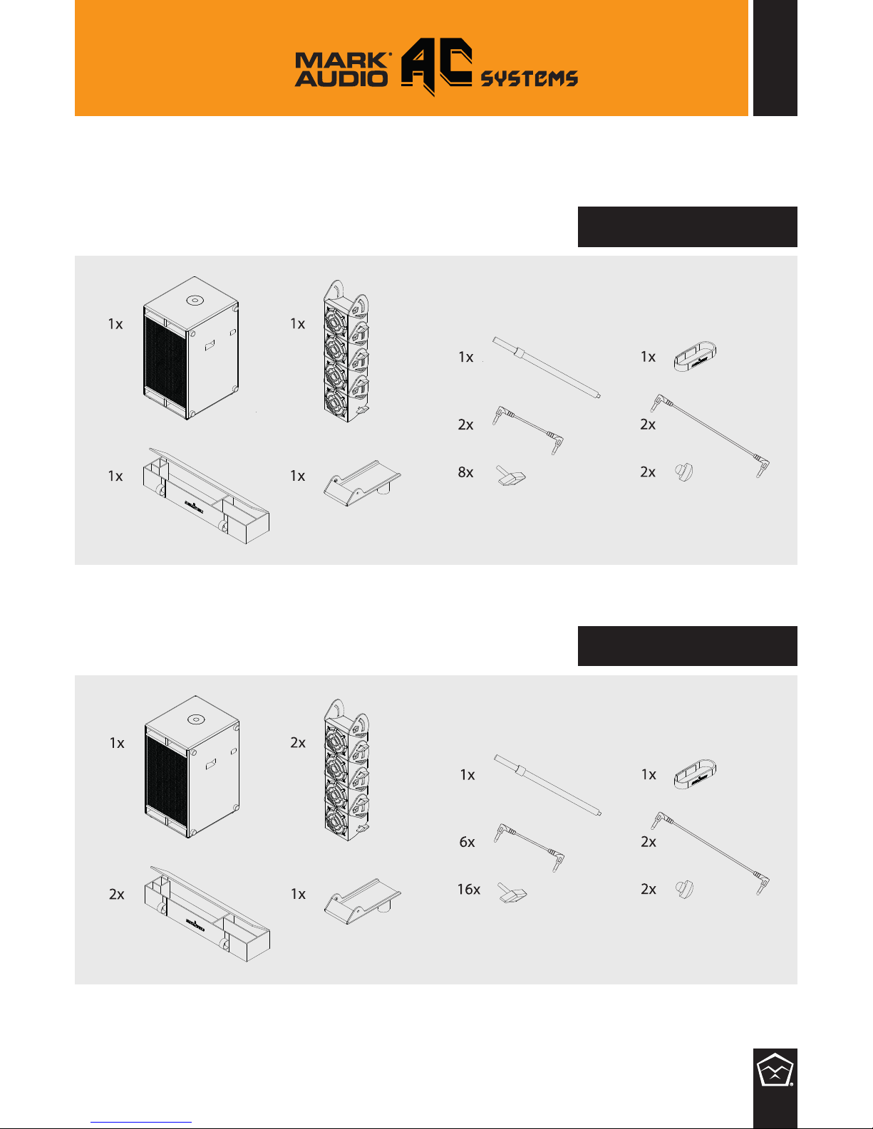
AC system 1
AC system 2
WHAT’S IN THE BOX
Page 5

4
INTRODUCTION
The AC systems is a portable active sound system (composed by a modular line
array plus a subwoofer) that combines quality of sound and design with high
operating efciency of power amplier.
Modularity is the keyword of this innovative system, designed for one-man band,
small band to big orchestra, home and movie theaters, churches... here 2 different
congurations which can be adapted to all your needs giving unparalleled exibility
whatever the application: from small to large audience!
AC System 1
features four 4.0” full range custom transducers (AC1) in the line
array satellite and one 2x10” subwoofer (AC102);
AC System 2
features eight 4.0” full range custom (AC1) in the line array satellite
and one 2x10” subwoofer (AC102);
AC Systems include high power class-D ampliers, the AC102 subwoofer features
a two-way amplier with DSP controlled crossover (500W for low channel +
500W for high channel).
The processing of the AC DSP allows to deliver a high output from these small
systems with a precise and focused response on both low and high frequencies
and a quick control of distorsion.
AC Systems design offers a perfect listening experience to the audience with its
accurate sound.
The installation is easy and simple and the different mounting setup options are
available to suit every taste and need of the listener.
The innovative design of the satellites allows to angle them for best setting as for
each type of application.
Page 6
5
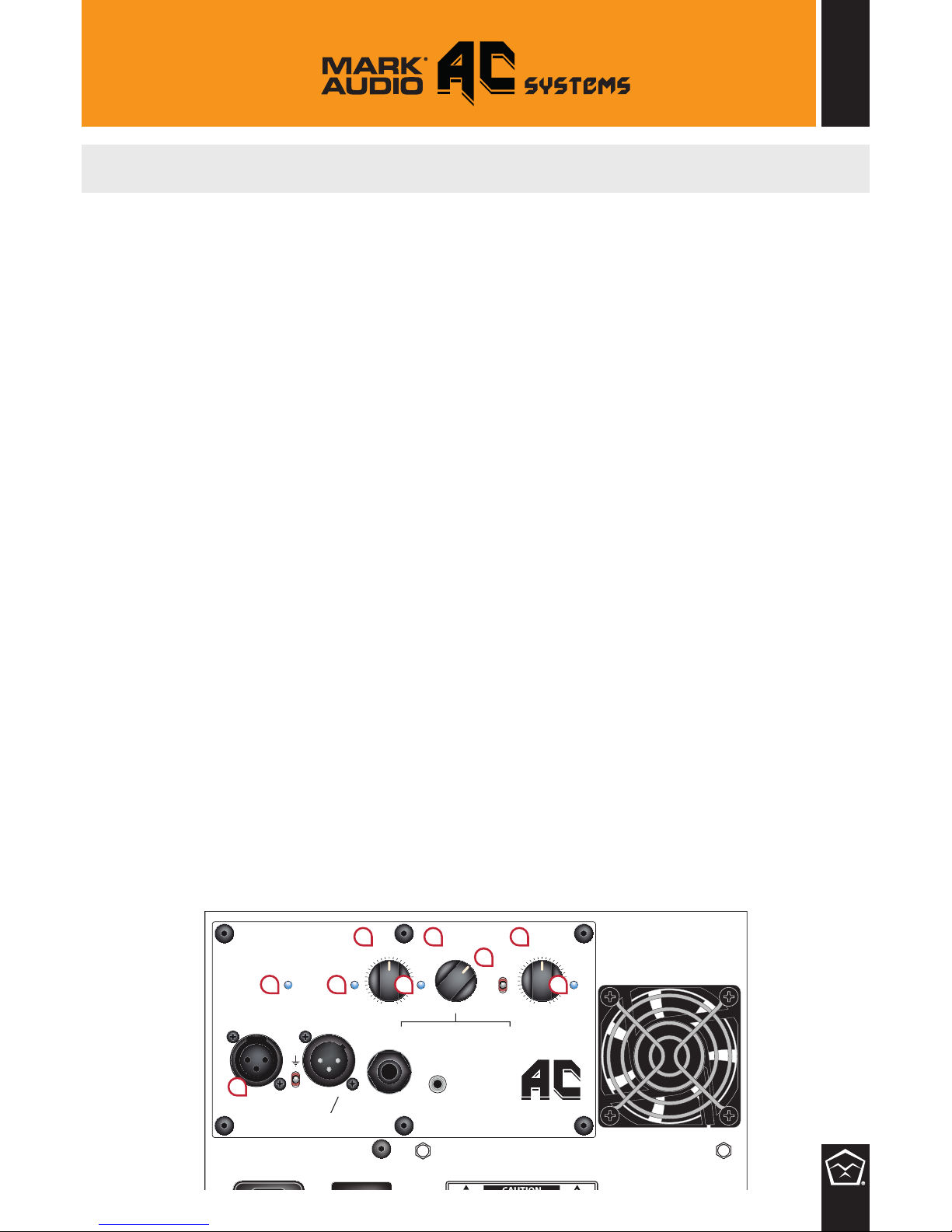
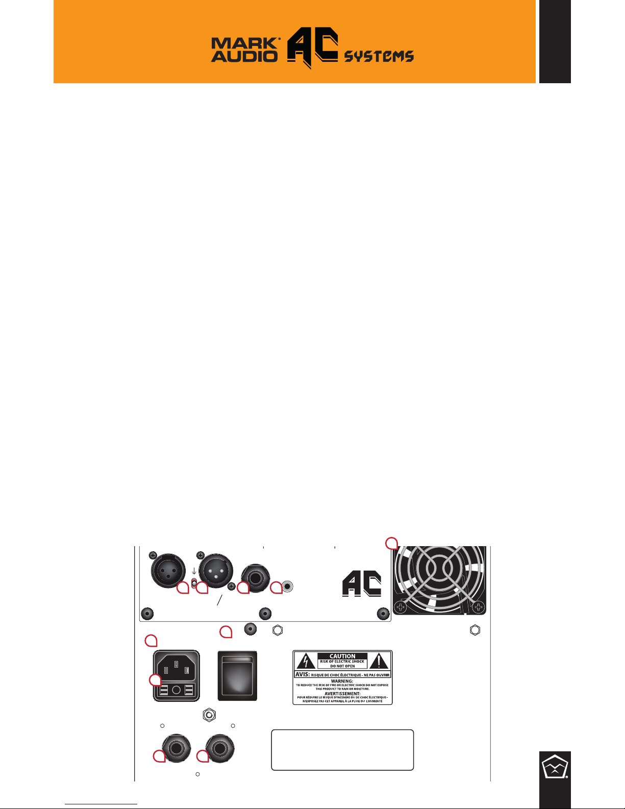
SUBWOOFER CONTROL PANEL – AC102
CLIP SUB (1) and HIGH (2)
The clip LEDs allow you to set the optimal level of the signal sent to the system’s speakers.
To nd the optimal level back off the power amp level (MASTER) so that the LEDs rarely
turn on.
GAIN INSTRUMENT (3)
This knob regulates the gain level of the INSTRUMENT input.
INSTRUMENT CLIP (4)
This clip LED allows you to set the optimal gain level of your signal due to instrument
input.
PRESETS (5)
This selector allows you to choose between 6 different equalization settings, optimized
for the use with the different systems:
AC System 1 (1)
AC System 1 with Boost (2)
AC System 2 (3)
AC System 2 with Boost (4)
AC 360° (5)
AC 360° x2 (6);
MONO/STEREO SWITCH (6)
When a stereo signal is connected to the AUX Input and you’d use two Markaudio system
in STEREO conguration selecting this switch on Stereo mode allows to send one of the
two channel of the stereo signal to the second system via XLR LINK. Select the switch in
MONO in case of only one Markaudio System or if you’d link two systems in MONO mode.
MASTER LEVEL (7)
This is the MASTER Volume level.
ON (8)
Power status indicator LED.
INPUT XLR (9)
XLR Balanced Input. The XLR 3-pole female jack is electronically balanced (hot pole:
#2). You can use unbalanced sources only if your cables have pole 3 jumpered to pole
1. Important: when powering up, turn on your sound source (CD player and mixer, for
example) before turning on the MarkAudio cabinets. When powering off, turn the cabinets
off rst.
OFF
GND
LIFT
INPUT
XLR
LINK XLR LEFT
MONO STEREO INPUT
INPUT
INSTR.
CLIP
SUB
CLIP
HIGH
CLIP
INSTR.
ON
PRESETS
STEREO
4
3
2
1
5
6
MONO
MASTER
-∞
Max
GAIN INSTR.
Min Max
AUX
1_AC Sy. 1
2_AC Sy. 1 Boost
3_AC Sy. 2
4_AC Sy. 2 Boost
5_AC 360
6_AC 360 Boost
1
9
2 4
6
8
5 73
Page 7
6
GROUND LIFT (10)
This switch may be needed for the cancellation of hum due to ground loops with other
apparatuses;
LINK XLR/LEFT (11)
Line out to connect another Markaudio system to the principal system; it performs as a
LINK (MONO mode) or it sends only the LEFT CHANNEL (STEREO mode) when a stereo
signal is connected to the AUX INPUT.
INPUT INSTRUMENT (12)
Line input 1/4” jack (for direct plugging a MONO instrument).
AUX INPUT (13)
Line input jack for plugging a STEREO audio signal through mini-jack connector.
COOLING (14)
Forced ventilation stabilizes the working temperature of electronic components for
continuous performance, even after a long period of operation.
Avoid using the loudspeaker on irregular surfaces that might block the vents.
AC POWER SOCKET (15)
VDE power jack for connecting the power cable from the unit to a wall power source.
Make sure the unit is grounded; all three terminals of the AC power plug must be connected
to avoid any injury to the user or damage to the unit.
Markaudio powered speakers and amps are manufactured to be used in the country
where they have been sold, and are factory preset to that country’s voltage. So make
sure you’re sending the correct voltage to your amp before you connect it to AC power.
FUSE (16)
Fuse housing.
ON/OFF SWITCH (17)
On/off power switch.
POWER OUT 1 (18)
Use this output to connect the AC module/s as showed at the following CONNECTIONS
instructions.
POWER OUT 2 (19)
Use this output to connect the AC module/s as showed at the following CONNECTIONS
instructions.
OFF
ON
POWER POWER
OUT 1 OUT 2
GND
LIFT
INPUT
XLR
LINK XLR LEFT
MONO STEREO INPUT
INPUT
INSTR.
CLIP
SUB
CLIP
HIGH
CLIP
INSTR.
ON
PRESETS
STEREO
4
3
2
1
5
6
MONO
MASTER
-∞
Max
GAIN INSTR.
Min Max
AUX
1_AC Sy. 1
2_AC Sy. 1 Boost
3_AC Sy. 2
4_AC Sy. 2 Boost
5_AC 360
6_AC 360 Boost
101811
19
17
15
16
12 13
14
Page 8
7
CONNECTIONS AC systems
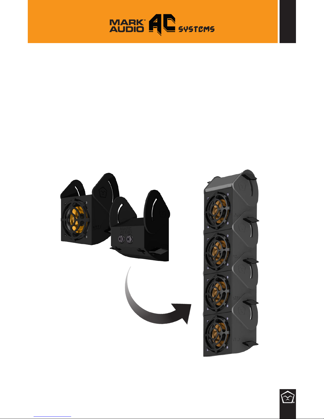
AudioChain is composed by different modules, each one called AC1.
AC system 1 is composed by 4 AC1, AC system 2 is composed by 8 AC1.
Each module ts to another one and can be locked, after ruling the angle you
prefer, by a couple of wing screws (cockerels).
AC1
Page 9
8
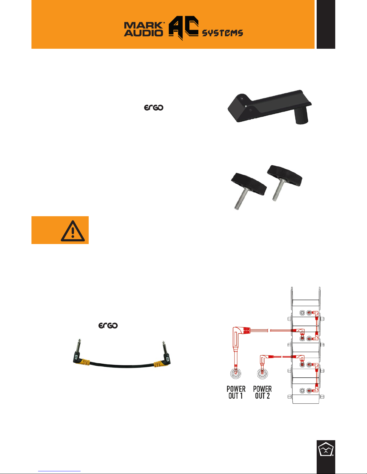
1. Put the AC102 on the oor vertically or
horizontally;
2. Screw the rod of the AC /
SPEAKER POLE on the AC102 and
insert the “top plate pole mount”
on the top;
3. Fix 4 AC1 (linked between them with
wing screws) to the “top plate pole
mount” with other 2 screw wings;
4. Take 2 (AC system 1) or 6 (AC system 2)
‘short’ jack cables and link AC1 modules
as shown in the table;
WARNING: before to remove
them from the last module
(which not connect two
modules) do not screw
completely the last screw
wings because you risk to
damage the mechanical
guides;
INSTALLATION
TOP PLATE POLE MOUNT
COCKERELS
AC / SHORT CABLE
Page 10
9
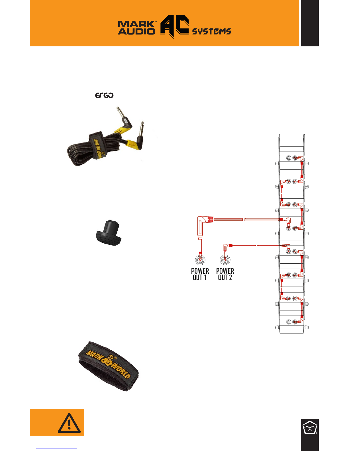
WARNING: the system MUST be
installed in the following way or the
amplier could be damaged.
6. Put 2 jack caps to the rst and
the last AC1;
7. Use the “Velcro band” to link
long cables;
8. Link the power cord and turn on
your system.
JACK CAP
STRAP CABLE
5. Take 2 ‘long’ jack cables and link
“Power Out 1” and “Power Out 2”
as shown in the previous table;
AC / LONG CABLE
Page 11
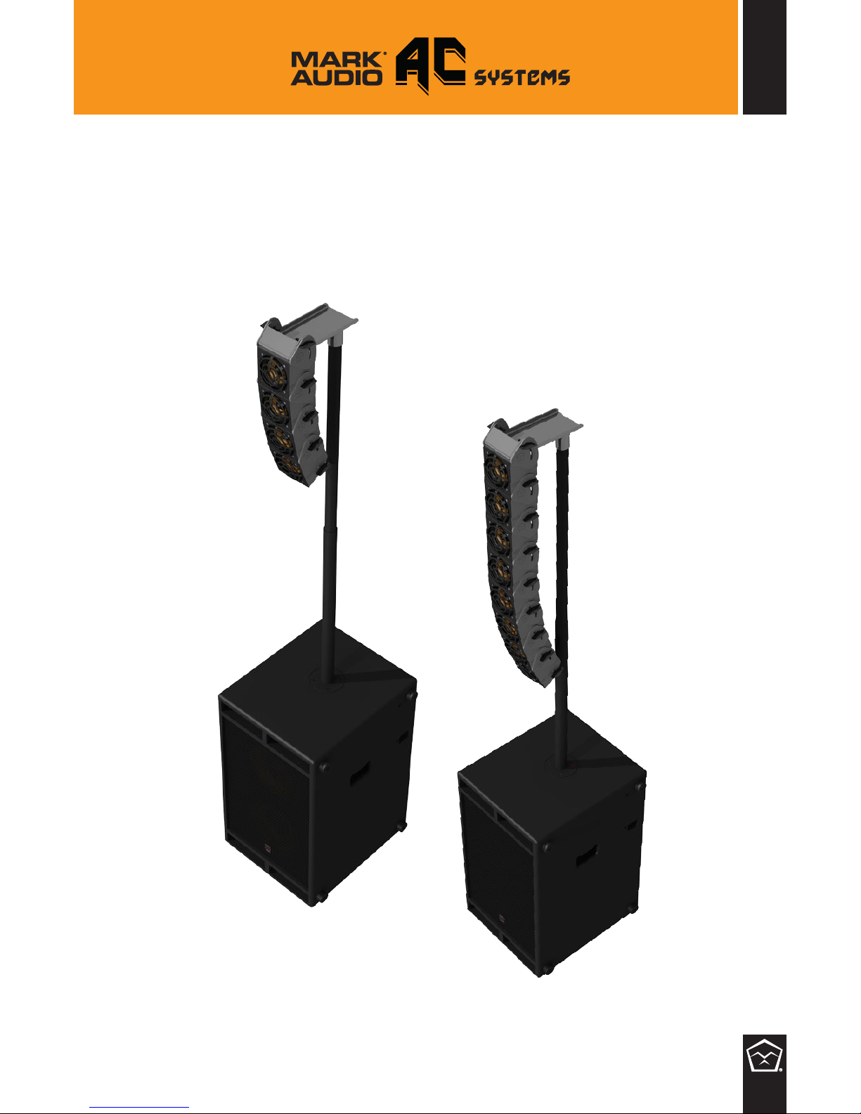
10
AC J-shape array conguration (AC System 1 or AC System 2)
INSTALLATION - MORE CONFIGURATIONS
Page 12
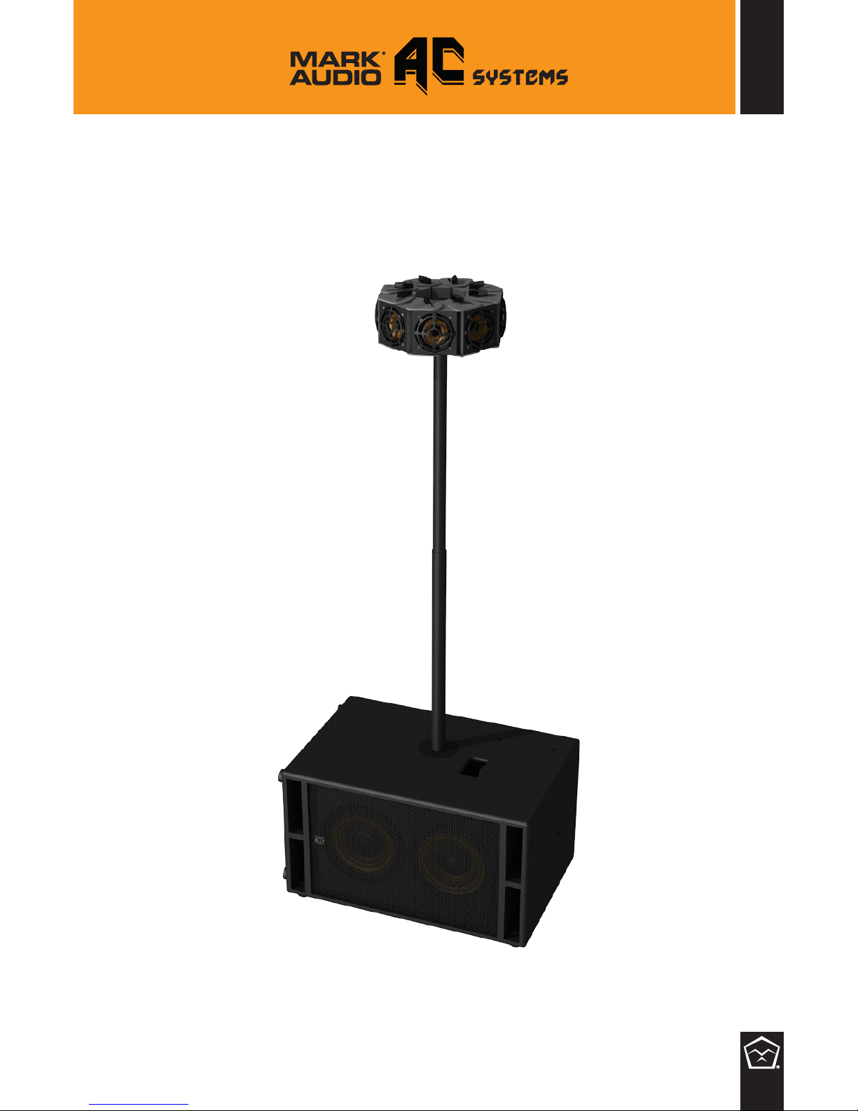
11
AC 360° conguration (AC System 2)
Page 13
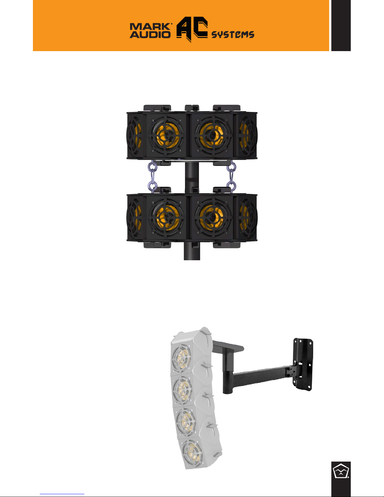
12
AC system 1 and AC system 2
Wall Mount conguration
AC 360° x 2 conguration (AC System 2 + 8 AC1 )
Page 14
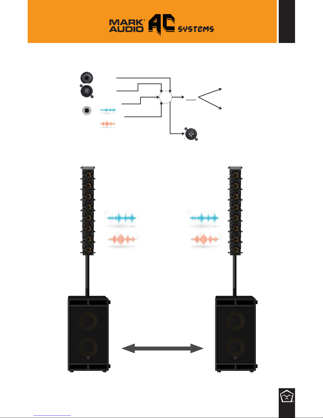
13
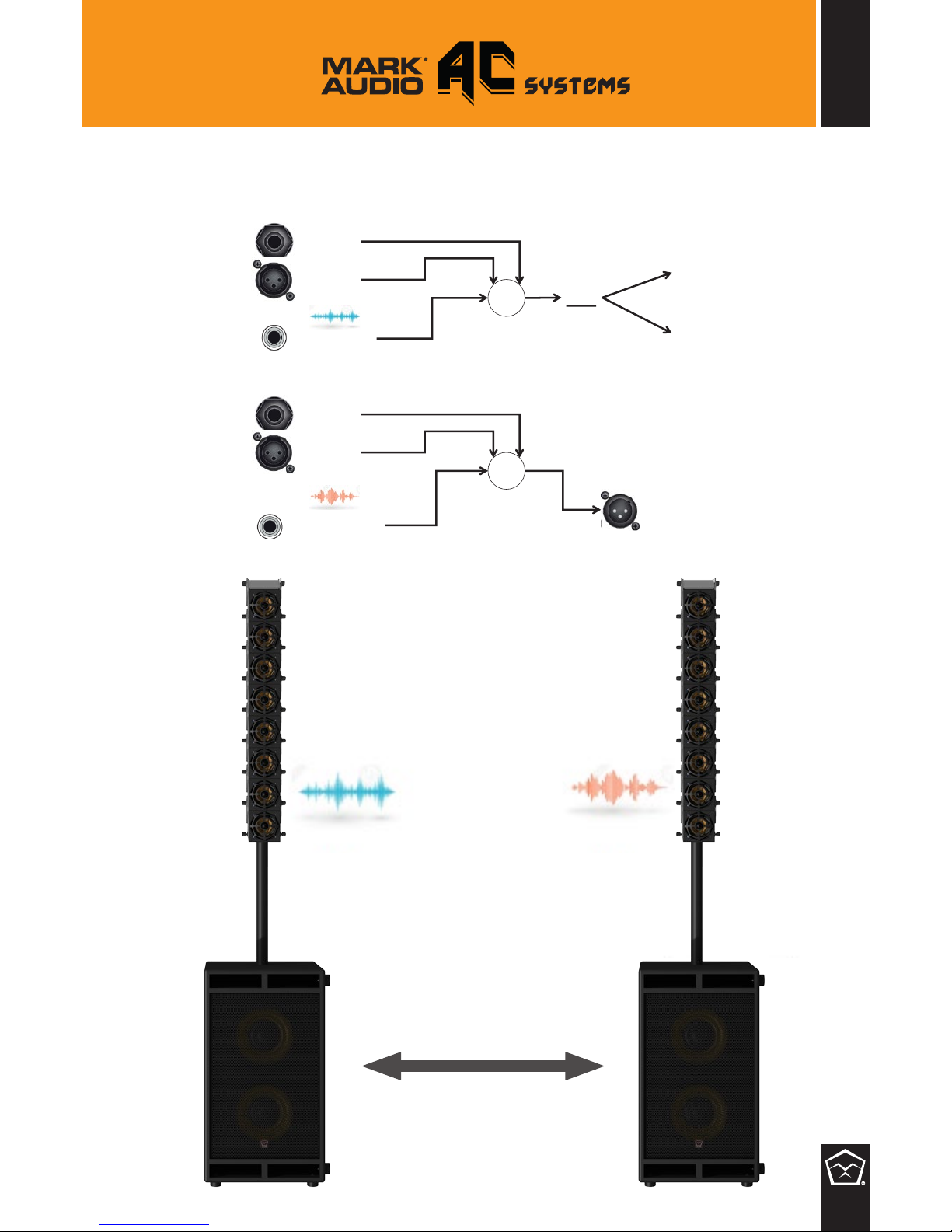
MONO MODE (2 x AC System 1 or 2 x AC System 2) through LINK XLR;
Instrument
XLR Input
LEFT Aux Input
RIGHT Aux Input
DSP
AMPLIFIER
Satellite
AMPLIFIER
Sub
+
Link
LEFT + RIGHT LEFT + RIGHT
XLR cable
Page 15
14
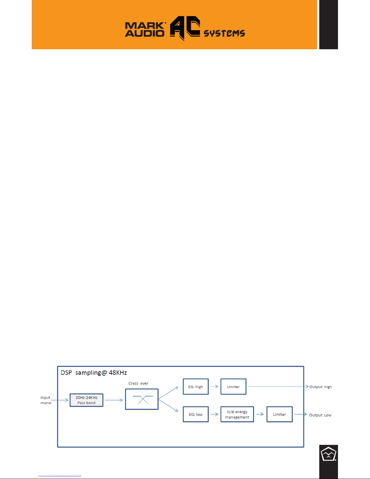
STEREO MODE (2 x AC System 1 or 2 x AC System 2) through LINK XLR;
Instrument
XLR Input
LEFT Aux Input
DSP
AMPLIFIER
Satellite
AMPLIFIER
Sub
+
RIGHT Aux Input
Instrument
XLR Input
+
Link
LEFT RIGHT
XLR cable
Page 16
15
TECHNICAL DETAILS
AC SYSTEM 1
ACOUSTICAL SPECIFICATIONS
Frequency response: 50 Hz- 20 kHz
Max SPL: 126dB
Horizontal coverage angle: 90°
Vertical coverage angle: 30°
Satellite: 4x4.0”, 16 Ohm
Sub: 2 x 10”, 4 Ohm
INPUT/OUTPUT SECTION
Input connectors: Jack-XLR male-AUX
Output connectors: XLR female
Input sensitivity: -1.1 dBu (@1 kHz)
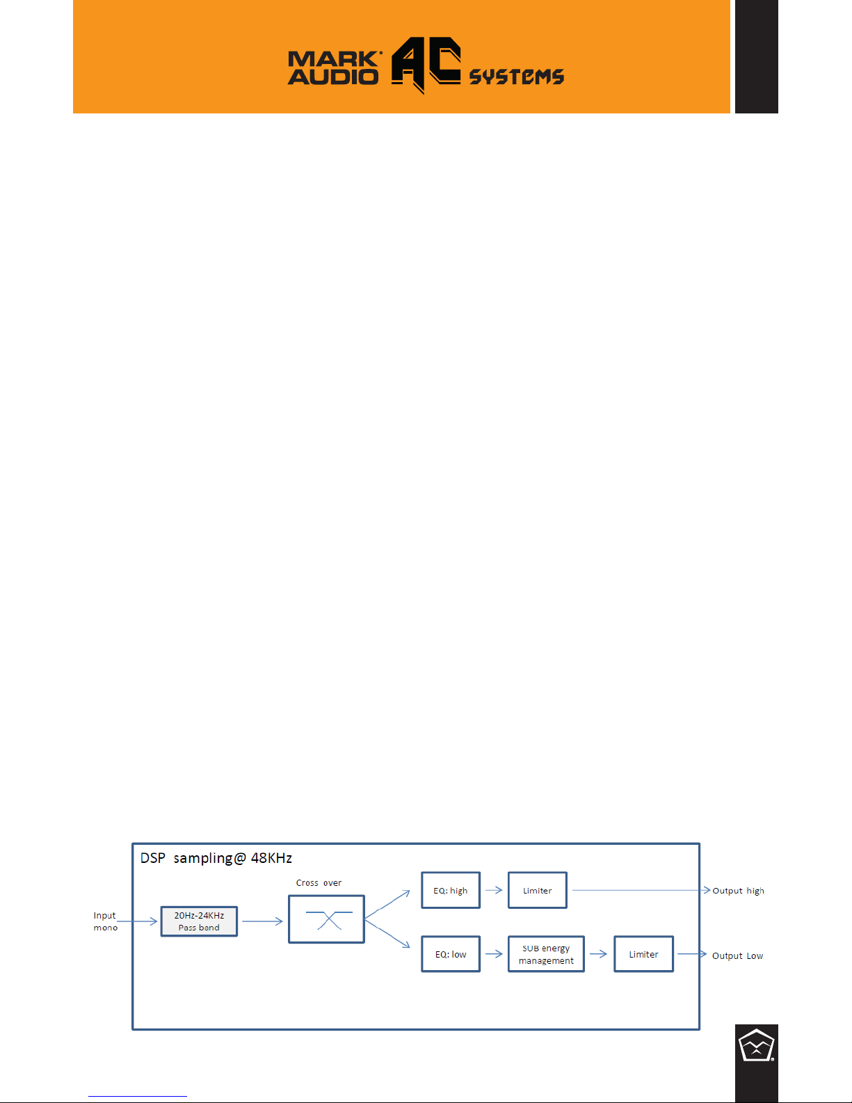
DSP PROCESSOR SECTION
Crossover frequencies: 180 Hz
Protections: Thermal, rms
Limiter: Soft limiter
Controls: Volume, EQ
AMPLIFIER
Total Power: 2000 W PEAK (@ 4 Ohm)
High frequencies: 1000 W PEAK (@ 4 Ohm)
Low frequencies: 1000 W PEAK (@ 4 Ohm)
Total Power: 1000 W RMS (@ 4 Ohm)
High frequencies: 500 W RMS (@ 4 Ohm)
Low frequencies: 500 W RMS (@ 4 Ohm)
Cooling: Convection
Power Connection: VDE connector
CABINET
Cabinet Material: multiply poplar
Handles: 2 side
Pole Mount/Cap: Yes
Colour: Black
PHYSICAL
Weight Satellite: 3Kg
Weight SUB: 23Kg
Fullrange Speaker Pole mount
Height: 1.25m (min) / 1.7m (max) with horizontal sub;
1.43m (min) / 1.88m (max) with vertical sub.
Page 17
TECHNICAL DETAILS
AC SYSTEM 2
ACOUSTICAL SPECIFICATIONS
Frequency response: 50 Hz- 20 kHz
Max SPL: 129dB
Horizontal coverage angle: 90°
Vertical coverage angle: 30°
Satellite: 8x4.0”, 8 Ohm
Sub: 2 x 10”, 4 Ohm
INPUT/OUTPUT SECTION
Input connectors: Jack-XLR male-AUX
Output connectors: XLR female
Input sensitivity: -1.1 dBu (@1 kHz)
DSP PROCESSOR SECTION
Crossover frequencies: 180 Hz
Protections: Thermal, rms
Limiter: Soft limiter
Controls: Volume, EQ
AMPLIFIER
Total Power: 2000 W PEAK (@ 4 Ohm)
High frequencies: 1000 W PEAK (@ 4 Ohm)
Low frequencies: 1000 W PEAK (@ 4 Ohm)
Total Power: 1000 W RMS (@ 4 Ohm)
High frequencies: 500 W RMS (@ 4 Ohm)
Low frequencies: 500 W RMS (@ 4 Ohm)
Cooling: Convection
Power Connection: VDE connector
CABINET
Cabinet Material: multiply poplar
Handles: 2 side
Pole Mount/Cap: Yes
Colour: Black
PHYSICAL
Weight Satellite: 6Kg
Weight SUB: 23Kg
Fullrange Speaker Pole mount
Height: 1.25m (min) / 1.7m (max) with horizontal sub;
1.43m (min) / 1.88m (max) with vertical sub.
16
Page 18
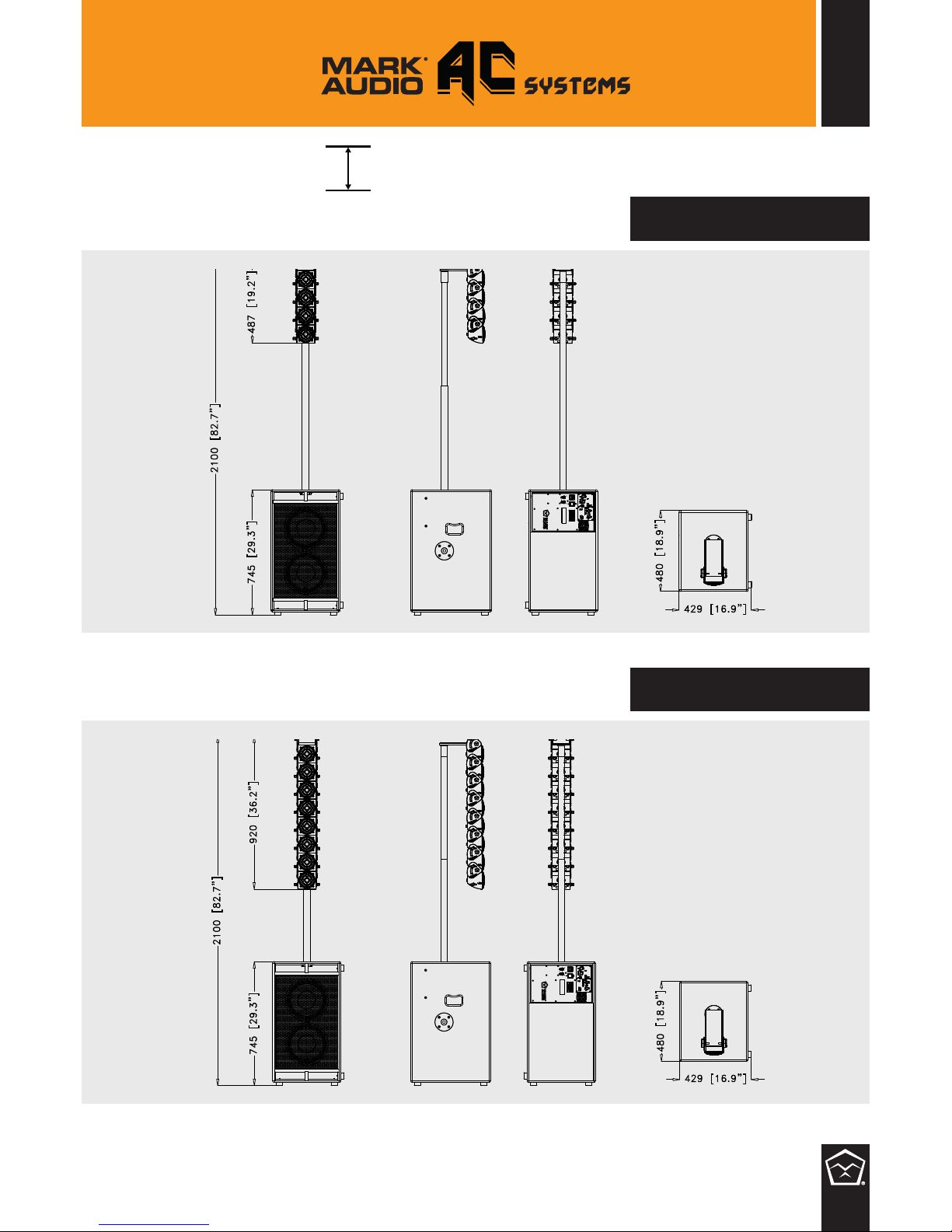
AC system 1
AC system 2
17
AC SYSTEMs size
mm
WEIGHT:
29.2 Kg / 64.4 lbs
WEIGHT:
32.2 Kg / 71 lbs
Page 19
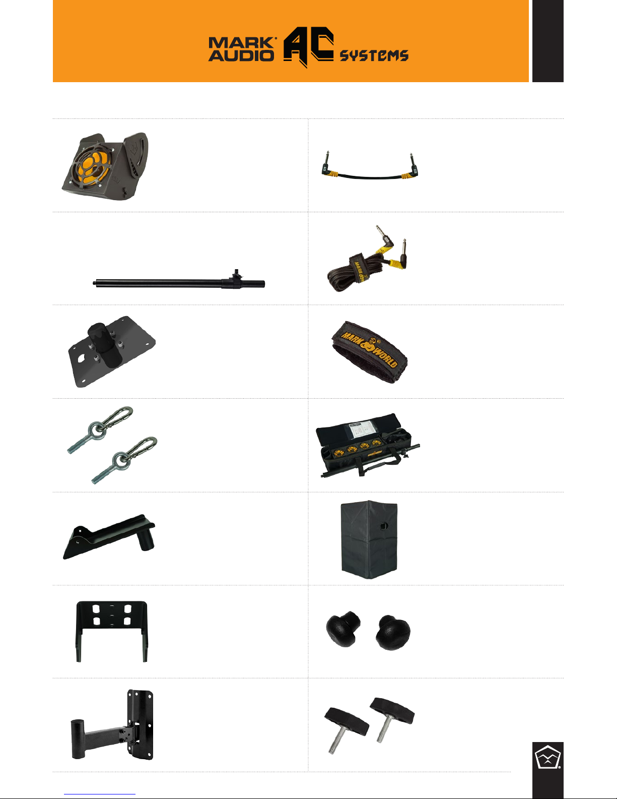
18
ACCESSORIES
AC1 module
Single AUDIO CHAIN 4”
loudspeaker module
AC long cable
2000 mm speaker cable
(1/4” to 1/4”) jack for AC
connection
AC 360 Plate
Accessory to set the
AC System2 in 360° mode
AC System Bag
Accessory to set the AC
System2 in 360° mode
AC Truss Top Plate
Mechanical Interface for
attaching the upper side
of AC System to trussing
or to other hardware
AC Top Plate Pole Mount
Top plate to x the
AC System to the pole
(included in the AC
Systems)
Jack cap
Mechanical Interface for
attaching the upper side
of AC System to trussing
or to other hardware
AC Speaker Pole
Speaker pole for mounting AC series on
subwoofers Ø 35
Strap cable
Speaker pole for mounting
AC series on subwoofers
Ø 35
AC 360 Slave
Accessory to set the AC
System2 + 2xAC4 in 360°
mode on two levels
AC 102 Cover
Accessory to set the AC
System2 + 2xAC4 in 360°
mode on two levels
AC Wall Mount
Mechanical Interface for
xing AC to a wall Ø 35
Wing Screws
Mechanical Interface for
xing AC to a wall Ø 35
AC Short Cable
150 mm speaker cable
(1/4” to 1/4”) jack for AC
connection
Page 20

18
POWER REQUIREMENT
100V; 120V; 230V; 240V 50/60Hz
(Voltage is factory preset according to region of sale).
Markaudio amps are manufactured to be sold and used in the country of purchase,
and are factory preset to that country’s voltage. Due to homologation issues, the
voltage may not be changed.
FUSE
EUROPE 6.3 A 250V T 5x20
AUSTRALIA/UK 6.3 A 250V T 5x20
USA/CANADA 10 A 250V T 5x20
JAPAN 12 A 250VT 5x20
 Loading...