

Page 1
© 2017 Mark 7® Reloading
This document is proprietary and confidential.
™ Installation Instructions
Box Contents and General Setup:
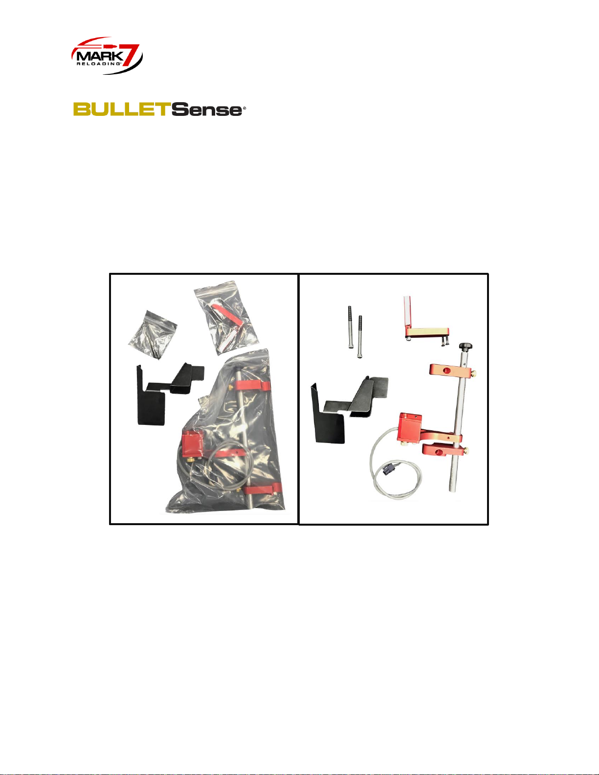
1. First review the box contents to make sure all parts are included:
a. Setup Insert
b. 650 BulletSense® Bracket Assembly
c. Mirror Bracket (Mirror Holder attached to Mirror Arm with 2X flat head screws)
d. 2X ¼-20 x 3” socket head cap screws for mounting to case feeder pole
e. Offloading bracket (modified for pistol calibers)
2. Check the software and firmware version installed on your machine and make sure it’s at
least the version listed below (or newer) before installing 650 BulletSense®. The latest
updates are available on the software updates page.
650 X: SW 00.01.13 FW 18
650 PRO: SW: 00.01.13 FW 26
Figure 1: Package Contents
Page 2
© 2017 Mark 7® Reloading
This document is proprietary and confidential.
3. The mirror holder is shipped with a protective film over the surface, before starting setup,
peel off the film. If required the mirror surface should be cleaned with water or isopropyl
alcohol, do not use any other types of solvents.
Installing BulletSense® Main Assembly:
1. Begin by clearing the shell plate and powering off the machine and tablet. Remove the
tablet, tablet holder, and offloading bin and set aside.
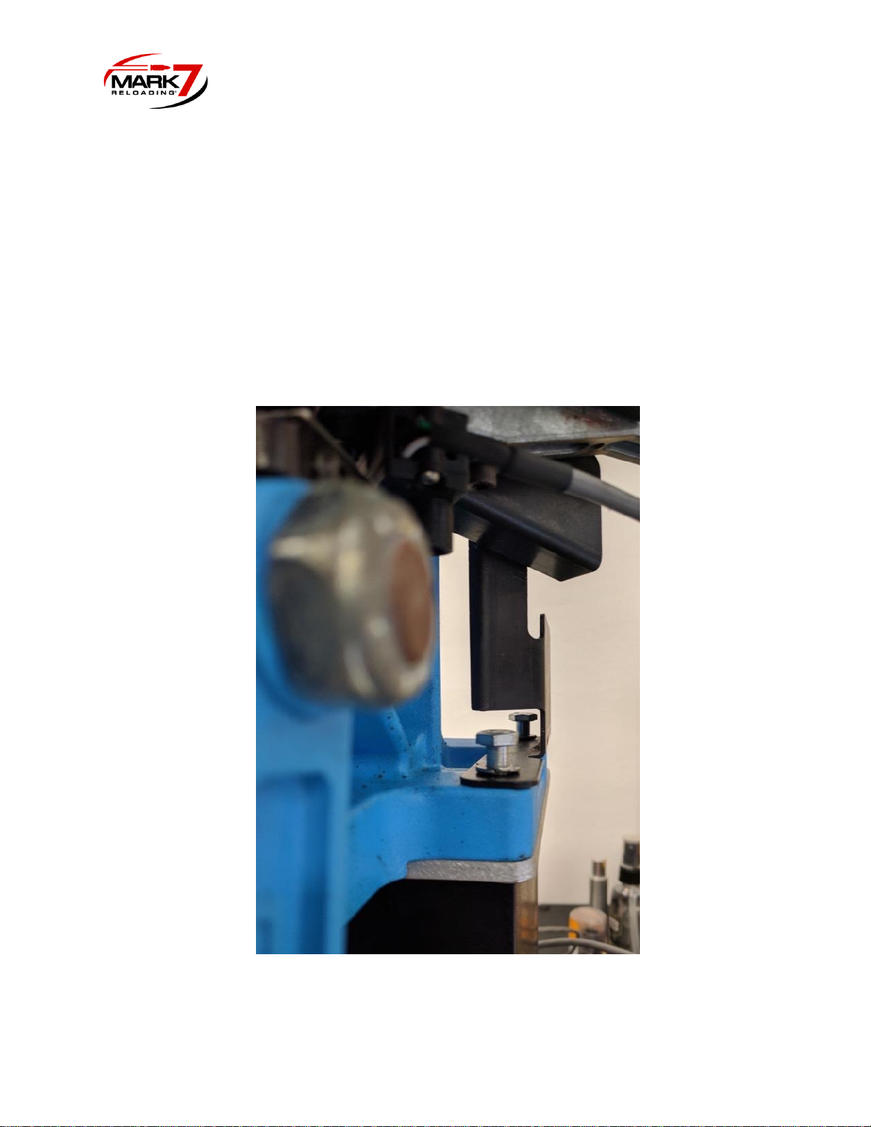
2. If Locate and remove the offloading bracket bolts (X2) with a 7-16” socket and set aside
(see Figure 2).
Figure 2: Removing offload bracket
Page 3

© 2017 Mark 7® Reloading
This document is proprietary and confidential.
3. The case feeder pole bolts need to be removed to install the BulletSense mounting
bracket. It is recommended to remove the case feeder or have an assistant hold the
pole in place so the case feeder does tip over. Carefully remove the case feeder pole
bolts with a 3/16” Allen wrench and with a 7/16” socket affixed on the opposite side of
the press (see Figures 3 and 4).
Figure 3: Case Feeder Mounting Bolt Locations
Page 4
© 2017 Mark 7® Reloading
This document is proprietary and confidential.
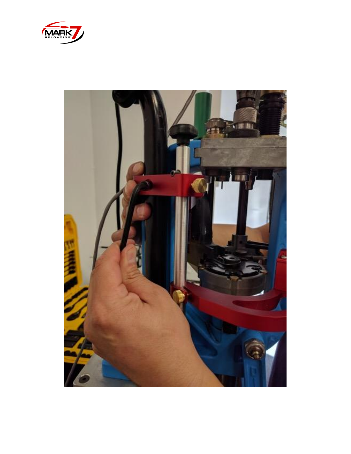
4. Install the 650 BulletSense Bracket Assembly as shown in the figure below (Figure 4).
Use the longer ¼-20” bolts provided.
Figure 4: Installing BulletSense on XL 650.
Page 5
© 2017 Mark 7® Reloading
This document is proprietary and confidential.
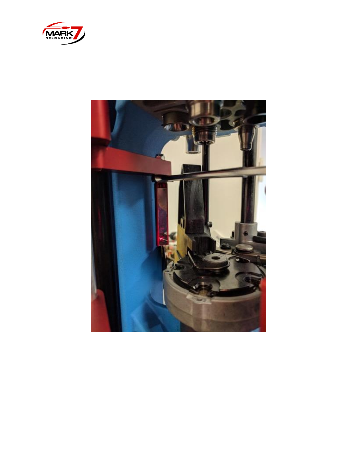
5. Attach the Mirror Bracket to the top bracket mount with the 2X flat head 8-32 X 1.25” cap
screws. The mirror then can be adjusted using a 3/8” open ended wrench.
Figure 5: Installing Mirror Bracket
6. Attach the offloading bracket provided with the screws that came with the press if you
are loading pistol calibers. Note for rifle calibers: The standard bracket can still be
used for rifle (it just covers the bottom of the mirror). This isn't an issue though because
the laser head is mounted higher due to the taller cases and longer projectiles.
Page 6
© 2017 Mark 7® Reloading
This document is proprietary and confidential.
Adjusting BulletSense® Laser for Station 4 and Station 5:
1. BulletSense can be configured in either station #4 or #5 (depending on whether you
are using a PowderSense).
Station 4: BulletFeeder dropper in Station 3 with standard crimp and seat dies.
Station 5: BulletFeeder dropper in Station 4. (using PowderSense® Powder check)
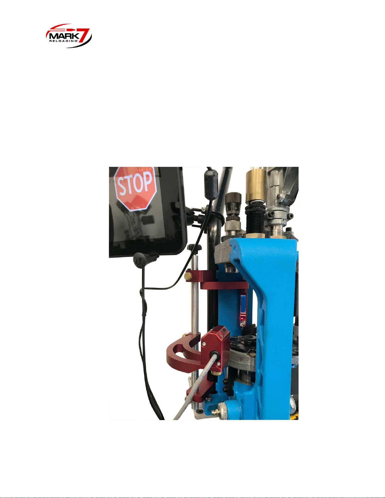
2. Once you decide which station, align the 650 BulletSense assembly with the mirror
holder by loosening the sensor head mount (middle arm) brass thumb screw and
rotating the sensor head to meet the mirror (see Figure 6).
Figure 6: Lining Up Laser with Mirror (Crude Adjustment)
Page 7
© 2017 Mark 7® Reloading
This document is proprietary and confidential.
3. Plug in the Sensor into Port #3 and power on the console which will automatically turn
on the laser. When you first power on the sensor look at the mirror to see where the
laser beam is directed. Use a thick white card/flat object to help find the exact position if
it’s difficult to detect the position.
**Please do not look directly into laser beam or directly at reflection in mirror**
WARNING – Class 3R laser: Avoid eye contact at all times; do not look directly
into the laser when adjusting the laser alignment.
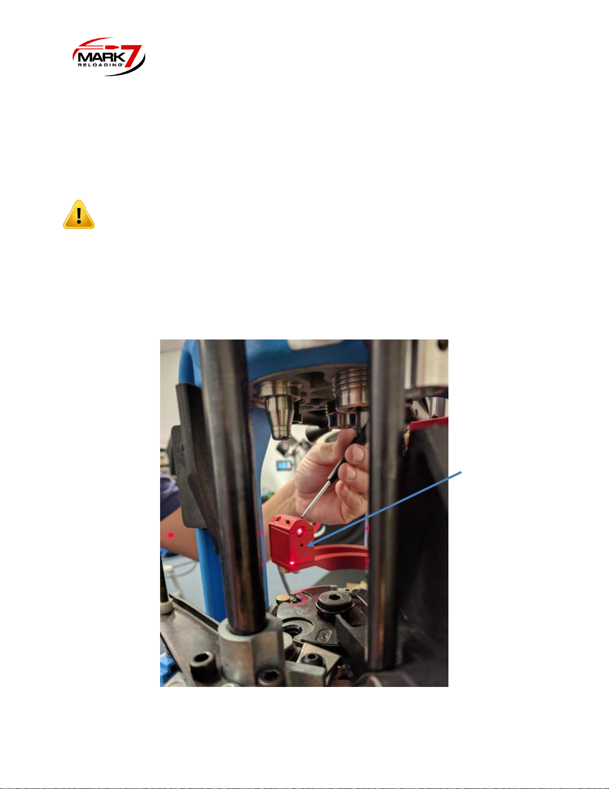
4. Adjust Laser beam onto the mirror with the 2X 6-32” set screws on the top of the
assembly with a Torx screwdriver size T6 x 40mm. Once the Laser diode is hitting the
mirror surface rotate the mirror using a 3/8” wrench so the laser beam is reflected back
to the sensor main body. Once the reflected laser beam appears on the sensor main
body, continue adjusting the set screws a little at a time to direct the laser beam into the
sensor hole as shown in Figure 7.
Figure 7: Adjusting Laser
Sensor hole
Page 8
© 2017 Mark 7® Reloading
This document is proprietary and confidential.
5. Next the sensor vertical height must set for the given caliber and projectile being used.
This must be performed when the platform assembly is in the home position. Before
making the vertical adjustment perform a system calibration so the platform stops in the
home position.
6. To set the vertical adjustment, place a case with the neck expanded (pistol only) in
Station #4 or #5 and place a bullet in the proper orientation into the case at the level
where it would be when dropped from the Mr. Bulletfeeder drop tube.
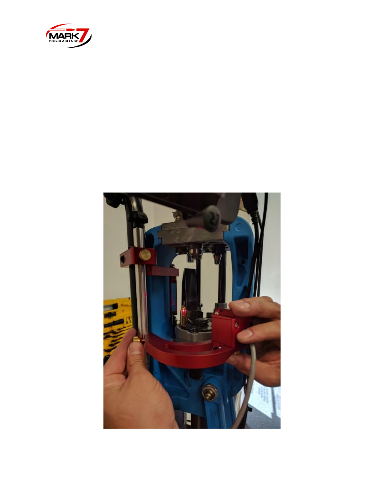
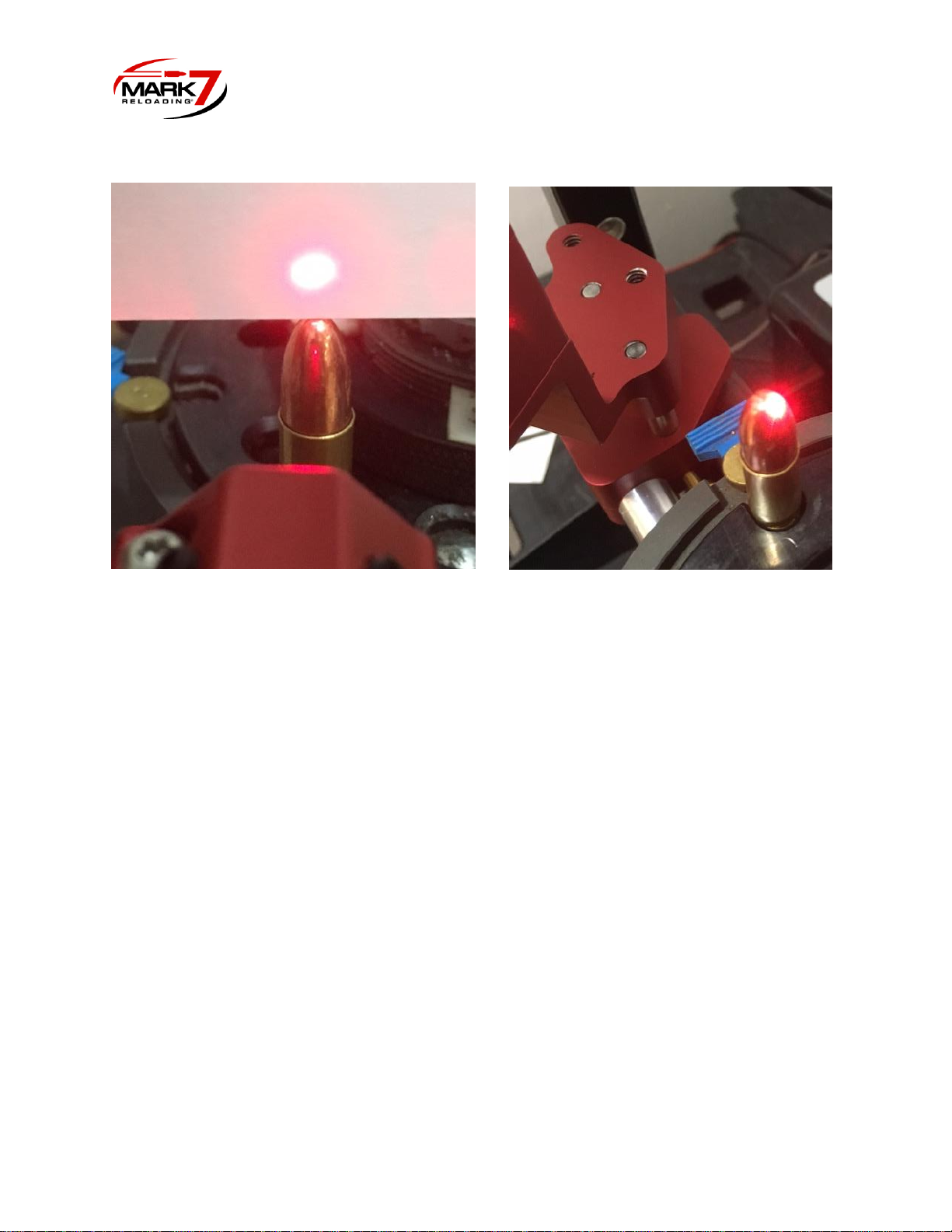
7. Loosen the brass thumb screw and gently position the sensor head mount (on middle
curved arm) so the laser beam goes OVER the tip of the bullet and hits the mirror, the
reflected beam should return and hit the tip of the bullet so the beam path is broken as
shown below (Figures 8 and 9). Once the height has been set, remove the bullet and
make sure the laser is still aimed at the sensor hole.
Figure 8: Setting Vertical height of laser
Page 9
© 2017 Mark 7® Reloading
This document is proprietary and confidential.
Figure 9: Beam Over Bullet (Left) the Reflected Beam Will Hit the Back of the Bullet (Right)
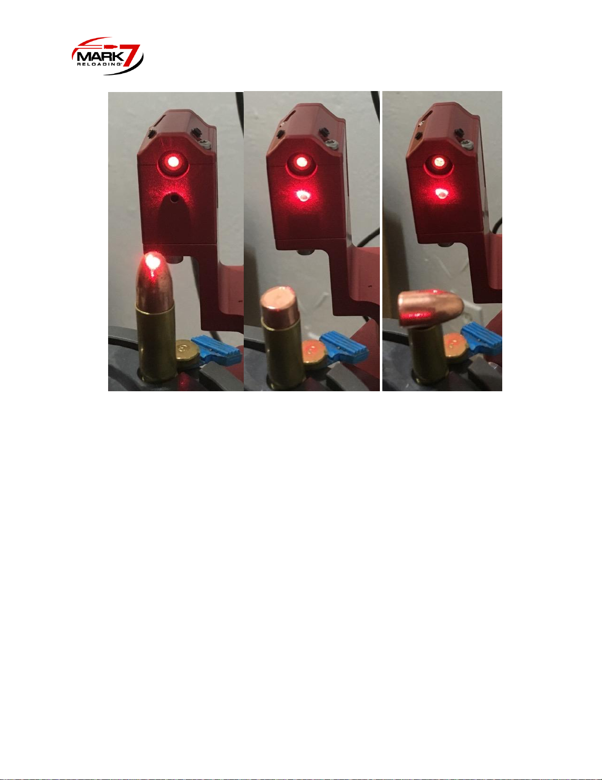
8. When the vertical height is correct a shadow will be cast on the sensor preventing the
sensor from “seeing” the laser beam. When the bullet is not present/upside down/
sideways the beam will pass over the bullet and contact the sensor triggering the
machine to stop.
9. It may be required to loosen the brass thumbscrew under the sensor head to add a slight
angle on the laser body to achieve a proper line of sight between the laser, bullet tip,
mirror and back to the sensor hole.
10. Once the proper height and adjustment has been achieved tighten the brass 2X thumb
screws located under the sensor head.
11. The sensor head assembly is designed to be rotated out of the way if you need to
access the shell plate or perform press maintenance. Use the plastic knob on top of the
rod to lift and rotate the sensor away from the machine.
Page 10
© 2017 Mark 7® Reloading
This document is proprietary and confidential.
Figure 10: Bullet Properly Oriented - Beam Interrupted (Left)
vs.
Bullets Improperly Oriented – Beam not interrupted (Center and Right)
Operating 650 BulletSense®:
1. With a clear shell plate enter the Reloader application, confirm that you have the
required software and firmware version or newer as outlined in the first page of this
document.
2. BulletSense® Plugged into I/O Port 3.
3. Confirm that the laser is aligned with the sensor opening.
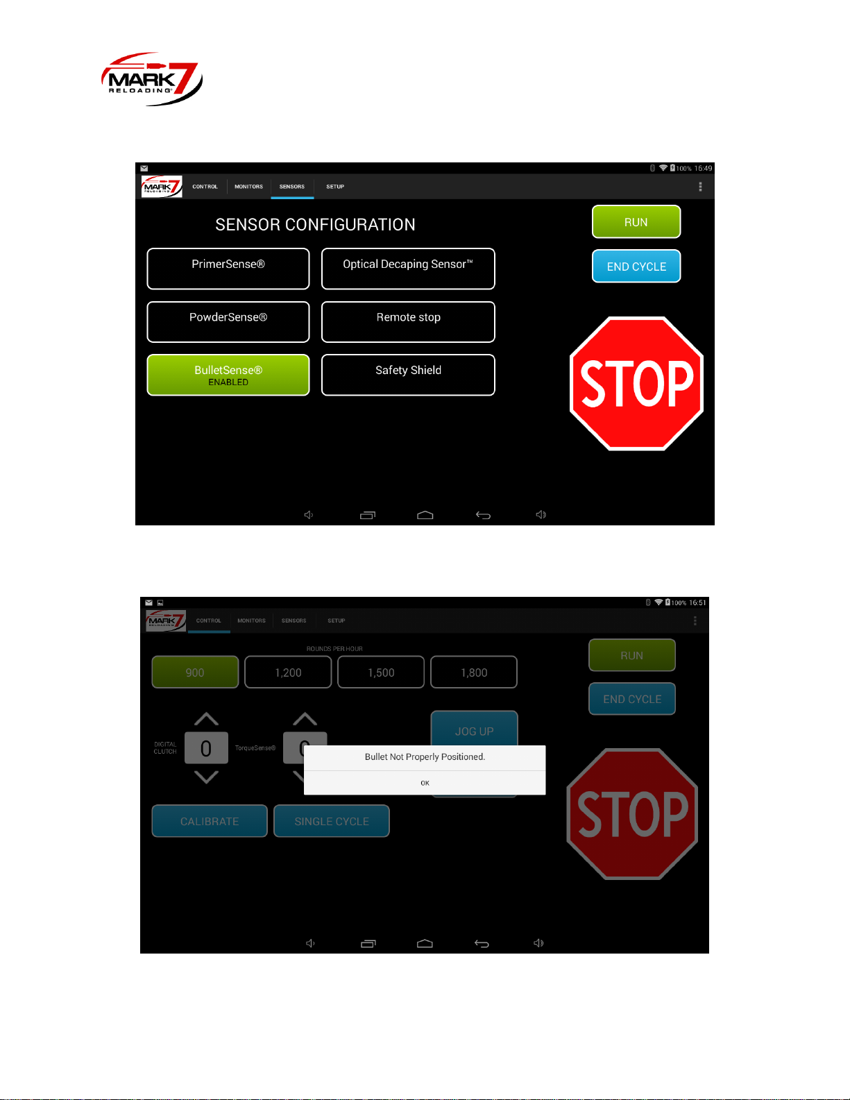
4. Perform a system calibration then select the sensors tab and make sure BulletSense® is
enabled. (See Figure 11).
5. Press RUN or Single Cycle. With a clear shell plate the following notification should
appear “Bullet Not Properly Positioned.” (see Figure 12).
Page 11
© 2017 Mark 7® Reloading
This document is proprietary and confidential.
Figure 11: Enabling BulletSense® on Sensor tab
Figure 12: Bullet Not Properly Positioned Notification
 Loading...