

Page 1

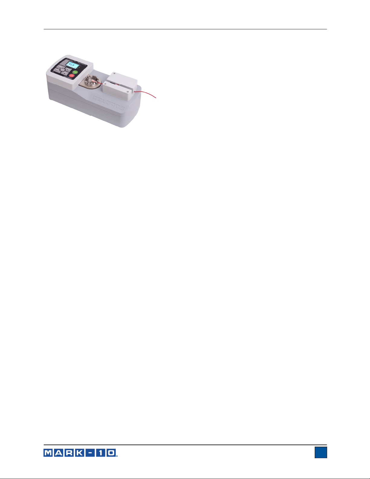
Model WT3-201M
MOTORIZED WIRE CRIMP PULL TESTER
User’s Guide
Page 2
Model WT3-201M Motorized Wire Crimp Pull Tester User’s Guide
Thank you…
Thank you for purchasing a Mark-10 WT3-201M wire crimp
pull tester, designed for pull test applications up to 200 lbF
(1,000 N).
With proper usage, we are confident that you will get many
years of great service with this product. Mark-10 instruments
are ruggedly built for many years of service in laboratory and
industrial environments.
This User’s Guide provides setup, safety, and operation
instructions. Dimensions and specifications are also provided. For additional information or answers to
your questions, please do not hesitate to contact us. Our technical support and engineering teams are
eager to assist you.
Before use, each person who is to use the WT3-201M should be fully trained in appropriate
operation and safety procedures.
TABLE OF CONTENTS
LIST OF INCLUDED ITEMS ............................................ 2
SAFETY ........................................................................... 2
SETUP .............................................................................. 3
HOME SCREEN AND CONTROLS ................................ 5
OPERATING MODES ...................................................... 9
UNITS OF MEASUREMENT ........................................... 9
DIGITAL FILTERS ........................................................... 9
PASS / FAIL LIMITS ..................................................... 10
SPEED .......................................................................... 11
AUTO START ............................................................... 12
PRELOAD ..................................................................... 12
PULL TO LOAD ............................................................ 13
LOAD HOLDING ........................................................... 13
BREAK DETECTION ..................................................... 14
AUTO SETTINGS ......................................................... 14
DATA MEMORY AND STATISTICS ............................. 16
COMMUNICATIONS AND OUTPUTS .......................... 17
PROFILES ..................................................................... 20
PASSWORDS ................................................................ 21
OTHER SETTINGS ........................................................ 22
FUNCTION ACTIVATION .............................................. 24
CALIBRATION ............................................................... 25
MAINTENANCE ............................................................. 28
SPECIFICATIONS ......................................................... 29
1
Page 3
Model WT3-201M Motorized Wire Crimp Pull Tester User’s Guide
1 LIST OF INCLUDED ITEMS
Qty. Part No. Description
1 WT3-201M Wire crimp pull tester
1 - Power cord
1 - Certificate of calibration without data (standard) or with data (optional)
1 09-1165 USB cable
1 - Resource CD (USB driver, user’s guides, MESURTM Lite software,
MESUR
1 WT3002 Optional ring terminal fixture
1 WT3003 Optional blank terminal fixture
1 WT3004 Optional carrying case
1 AC1049 Optional calibration kit
TM
gauge DEMO software, User’s Guide)
2 SAFETY
The following safety checks and procedures should be performed before and during operation:
1. Always consider the characteristics of the sample being tested before initiating a test. A risk
assessment should be carried out beforehand to ensure that all safety measures have been
addressed and implemented.
2. Wear eye and face protection when testing, especially when testing brittle samples that have the
potential to shatter under force. Be aware of the dangers posed by potential energy that can
accumulate in the sample during testing. Extra bodily protection should be worn if a destructive
failure of a test sample is possible.
3. Keep away from moving parts of the tester. Loose articles of clothing should not be worn. Long hair
should be covered to avoid a hazardous situation.
4. In those applications where samples can shatter, or other applications that could lead to a
hazardous situation, use of a machine guard is strongly recommended.
5. When the tester is not in use, ensure that the power is turned off to prevent accidental engagement
of any of the controls.
2
Page 4
Model WT3-201M Motorized Wire Crimp Pull Tester User’s Guide
3 SETUP
3.1 Mechanical Setup
3.1.1 Assembly
The tester is shipped completely assembled.
3.1.2 Mounting
Place the tester on a clean, flat and level work area free from vibration. If desired, the tester can be
secured to the work area with four 1/4-20 screws fastened into the underside of the base (depth of 0.5 in.
[12 mm]).
3.1.3 Installing the ring terminal fixture or blank terminal fixture
To install or uninstall the standard terminal fixture or optional fixture, loosen the screw in the center of the
fixture, remove, place the other fixture in the receptacle, and re-tighten the screw.
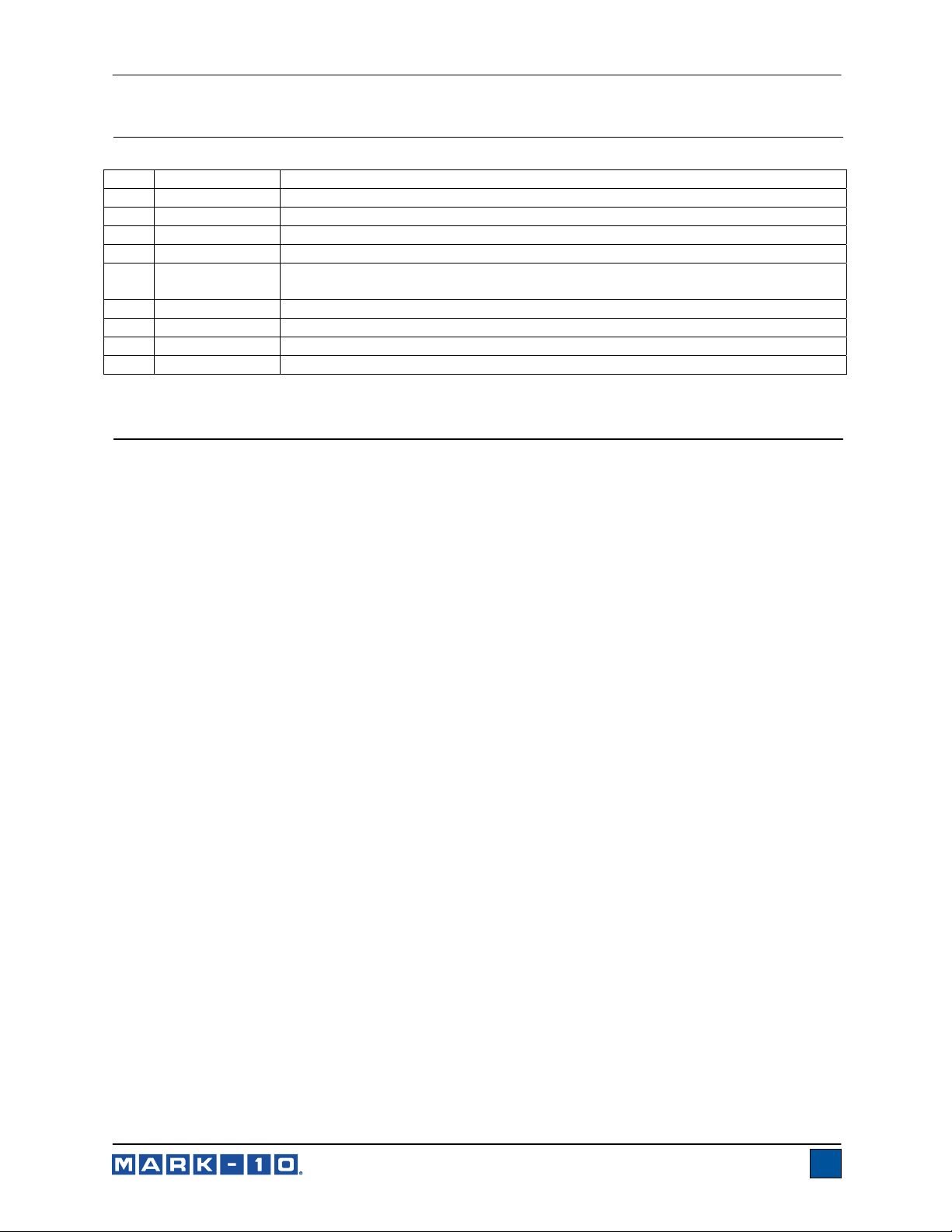
3.1.4 Sample setup
1. Secure the terminal into the standard terminal fixture or optional ring terminal fixture, as shown in
the images below. Index the fixtures until the desired slot or ring size is aligned with the cam
mechanism adjacent to the lever. The fixtures will click when indexing to each size selection.
2. Insert the loose end of the wire between the cams in the mechanism. Keep the wire taut as it is
inserted. If auto-start is enabled, the test will begin when the switch is activated (refer to later
sections for operational details). Refer to the image below:
3
Page 5
Model WT3-201M Motorized Wire Crimp Pull Tester User’s Guide
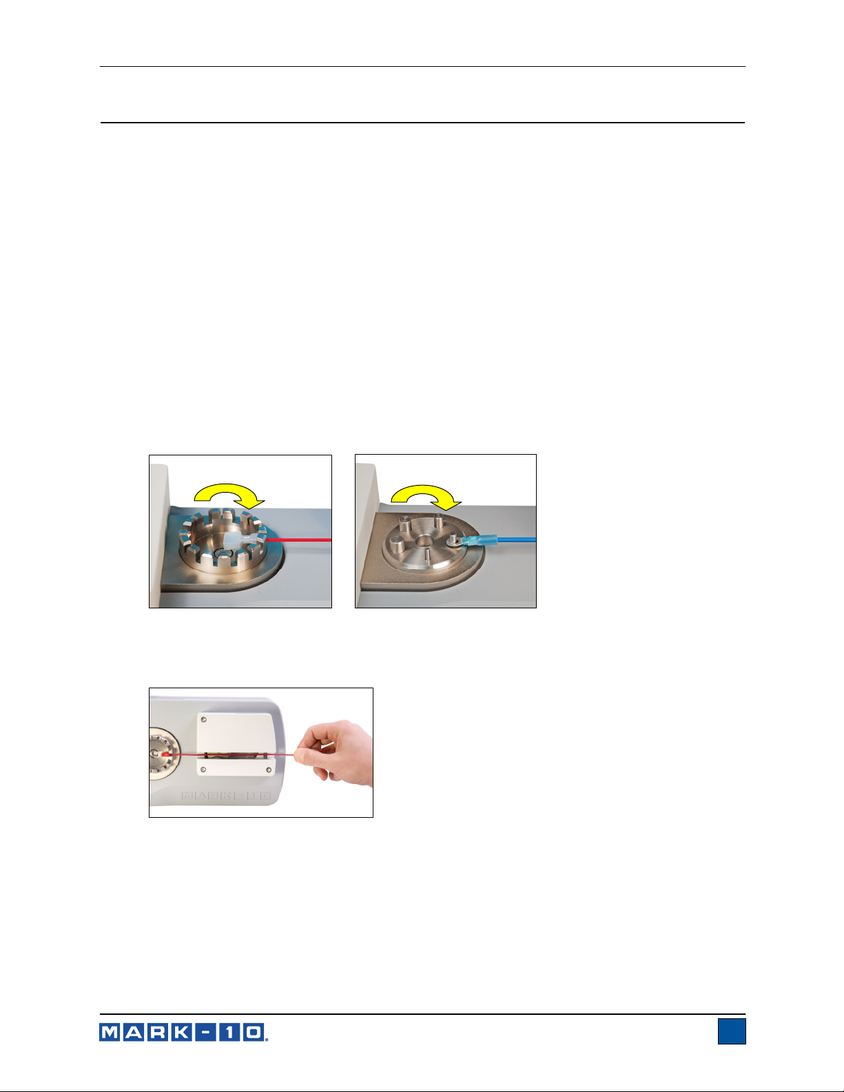
3. Note the protective red safety guard (circled, below), which automatically rotates into position as
the cam mechanism closes.
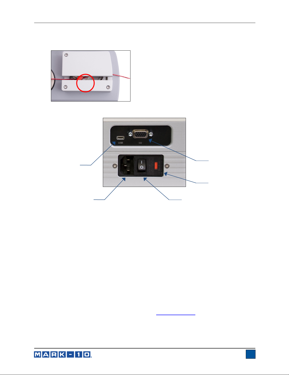
3.2 Connections and Outputs
1
5
4
3
2
1. Serial Connector
RS-232, set point, analog, Mitutoyo, and other outputs are provided. Refer to the
Communications and Outputs section for details.
2. Fuse
3. Power Switch
Use to turn power on and off.
4. Power Plug Receptacle
Plug the power cord in here. Refer to the Connecting power sub-section for important safety
information.
5. USB Connector
Plug the USB cable in here, for data output to a PC, PLC, printer, etc.
3.3 Installing the USB driver
If communicating via USB, install the USB driver provided on the Resource CD. Installation instructions
may also be found on the CD or may be downloaded from www.mark-10.com
.
Caution!
Install the USB driver before physically connecting the tester to a PC with the USB cable.
4
Page 6

Model WT3-201M Motorized Wire Crimp Pull Tester User’s Guide
Further instructions for configuring and using the gauge’s outputs are provided in the Communications
and Outputs section.
3.4 Connecting power
Plug one end of the power cord into its receptacle at the rear of the stand and the other end into a wall
outlet with local earth ground (3-prong connector).
Before turning on power, the following safety checks and procedures should be performed:
1. Never operate the tester if there is any visible damage to the power cord or the tester itself.
The WT3-201M is powered by 110V/220V. Any contact with this high voltage can cause
serious injury or even death.
2. Ensure that the tester is kept away from water or any electrically conductive liquids at all
times.
3. Make sure the electrical outlet powering the tester has local earth ground (3-prong connector).
4. The tester should be serviced by a trained technician only. Power must be disconnected
before disassembly.
After the above safety checks and procedures have been performed, the tester may be powered on and
is ready for operation.
4 HOME SCREEN AND CONTROLS
4.1 Demo Mode Functions
The WT3-201M is shipped in Demo Mode, which provides full functionality of all available functions for an
evaluation period of 160 operating hours. When this period has expired, any functions not purchased will
no longer be accessible.
After the initial power-up sequence, the display appears as follows:
*** DEMO MODE ***
All functions are
temporarily enabled.
Remaining demo time:
160 hours
Press ENTER.
The available optional functions are as follows:
1. Profiles
Save and recall sets of test parameters, such as speed, pass/fail limits, unit of measurement, etc.
Maximum of 500 profiles may be stored.
2. Load Holding
The tester will stop and maintain a specified load for a specified period of time.
3. Pull To Load
The tester will stop when the specified load has been reached.
5
Page 7

Model WT3-201M Motorized Wire Crimp Pull Tester User’s Guide
4. Date & Time Stamp
A date and time stamp is assigned to each saved data point.
5. Complete Options Package
Includes all of the functions listed above.
Refer to the Function Activation section for further instructions on how to activate functions.
6
Page 8
Model WT3-201M Motorized Wire Crimp Pull Tester User’s Guide
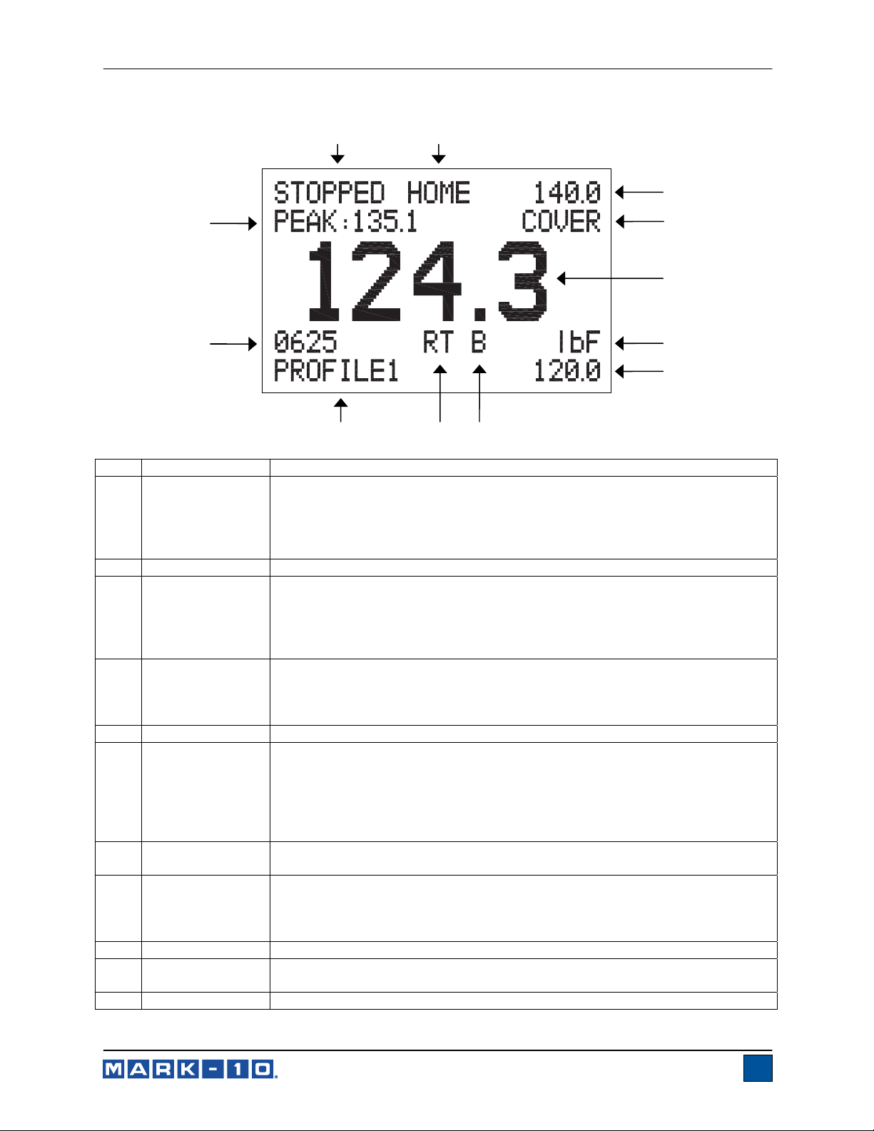
4.2 Home Screen
1
2
3
12
11
810
9
No. Name Description
Indicates one of the following statuses:
STOPPED
1 Status
2 Position
3 / 7
4 Message
5 Primary reading
6
8
9 Mode
10 Profile name
11
12 Peak force
Upper / lower
force limits
Unit of
measurement
Break detection
on/off
Number of data
points
PULLING
RETURNING (to the Home position)
HOLDING (Load Holding sequence in progress)
Indicates one of the following positions: HOME or LIMIT
Indicates the upper and lower acceptable force limits, as configured in the
Pass / Fail Limits menu. The upper and lower red “X” indicators adjacent to
the values illuminate if the displayed force is less than the lower limit or
greater than the upper limit. The green “checkmark” indicator illuminates if
the displayed force is within range.
Indicates one of the following messages:
COVER - the actuator cover is removed.
PL ON – Pull to Load (optional function) is active.
LH ON – Load Holding (optional function) is active.
The current displayed reading. See Operating Modes section for details.
The current measurement unit. Abbreviations are as follows:
lbF – Pound-force
ozF – Ounce-force
kgF – Kilogram-force
N – Newton
kN – Kilonewton
The letter “B” appears if the Break Detection function is enabled. Refer to the
Break Detection section for details.
The current measurement mode. Abbreviations are as follows:
RT – Real Time
PK – Peak
See Operating Modes section for details about each of these modes
Indicates the currently selected profile. See Profiles section for details.
The number of stored data points in memory, up to 2,000.
The maximum measured tension force. May be reset by pressing ZERO.
4
5
6
7
7
Page 9
Model WT3-201M Motorized Wire Crimp Pull Tester User’s Guide
4.3 Controls
Primary
Label
ENTER
ZERO
MENU
MODE
Primary Function
Various uses, as described in the
following sections.
Zeroes the primary reading and
peaks.
Enters the main menu.
Toggles between measurement
modes.
Secondary
Label
-
(UP)
ESCAPE
(DOWN)
Secondary Function
Navigates up through the menu and
sub-menus.
Reverts one step backwards through
the menu hierarchy.
Navigates down through the menu
and sub-menus.
Stores a value to memory, transmits
DATA
the current reading to an external
device, and/or initiates automatic
DELETE
Enables and disables Delete mode
while viewing stored data.
data output, depending on setup.
Starts motion. Press and release to
START
produce maintained motion. In
Maintenance mode, a key press
-
results in momentary motion.
Reverses motion. Press and release
to produce maintained motion until
STOP
Stops motion.
RETURN
return to the Home position. In
Maintenance mode, a key press
results in momentary motion.
4.4 Menu navigation basics
Most of the tester’s various functions and parameters are configured through the main menu. To access
the menu press MENU. Use the UP and DOWN keys to scroll through the items. The current selection is
denoted with clear text over a dark background. Press ENTER to select a menu item, then use UP and
DOWN again to scroll through the sub-menus. Press ENTER again to select the sub-menu item.
For parameters that may be either selected or deselected, press ENTER to toggle between selecting and
deselecting. An asterisk (*) to the left of the parameter label is used to indicate when the parameter has
been selected.
For parameters requiring the input of a numerical value, use the UP and DOWN keys to increment or
decrement the value. Press and hold either key to auto-increment at a gradually increasing rate. When
the desired value has been reached, press ENTER to save the change and revert back to the sub-menu
item, or press ESCAPE to revert back to the sub-menu item without saving. Press ESCAPE to revert one
step back in the menu hierarchy until back into normal operating mode.
Refer to the following sections for details about setting up particular functions and parameters.
8
Page 10
Model WT3-201M Motorized Wire Crimp Pull Tester User’s Guide
5 OPERATING MODES
Caution!
In any operating mode, if the capacity of the tester has been exceeded by more than 110%, the
display will show “OVER” to indicate an overload. A continuous audible tone will be sounded until
the MENU key has been pressed or the load has been reduced to a safe level.
Three operating modes are possible with the WT3-201M. To cycle between the modes, press MODE
while in the home screen.
5.1 Real time (RT)
The primary reading corresponds to the live measured reading.
5.2 Peak (PK)
The primary reading corresponds to the peak tension reading observed. If the actual force decreases
from the peak value, the peak will still be retained in the primary reading area of the display. Pressing
ZERO will reset the value.
6 UNITS OF MEASUREMENT
The WT3-201M can display five different force measurement units. To change the unit, select Units from
the menu. The display will list the available units, as follows:
UNITS
* lbF
ozF
kgF
N
kN
Note: Changing the unit within this menu will not set the default unit. To always power on automatically
with the desired unit, configure the unit in the Initial Settings menu.
7 DIGITAL FILTERS
Digital filters are provided to help smooth out the readings in situations where there is mechanical
interference in the work area or test sample. These filters utilize the moving average technique in which
consecutive readings are pushed through a buffer and the displayed reading is the average of the buffer
contents. By varying the length of the buffer, a variable smoothing effect can be achieved. The selection
of 1 will disable the filter since the average of a single value is the value itself.
To access digital filter settings, select Filters from the menu. The display appears as follows:
DIGITAL FILTERS
(1 = Fastest)
Current Reading
8
Displayed Reading
512
9
Page 11
Model WT3-201M Motorized Wire Crimp Pull Tester User’s Guide
Two filters are available:
Current Reading – Applies to the peak capture rate of the instrument.
Displayed Reading – Applies to the primary reading on the display.
Available settings: 1,2,4,8,16,32,64,128,256,512,1024. It is recommended to keep the current
reading filter at its lowest value for best performance, and the displayed reading filter at its
highest value for best stability.
8 PASS / FAIL LIMITS
8.1 General Information
Pass / fail limits are useful for tolerance checking with red and green indicators and audible tones. Set
point outputs are also provided, for triggering an external device such as an indicator or alarm in process
control applications. Two limits, high and low, are specified and stored in the non-volatile memory of the
tester and the primary reading is compared to these limits. The results of the comparisons are indicated
through the three outputs provided on the 15-pin connector, thus providing “under”, “in range”, and “over”
signaling.
8.2 Configuration
To configure pass/fail limits, select Pass / Fail Limits from the menu. The display appears as follows:
PASS / FAIL LIMITS
Upper Disabled
* Upper Enabled
125.0
Lower Disabled
* Lower Enabled
122.5
Either one, two, or none of the limits may be enabled.
The upper limit is displayed in the upper right corner of the display, and the lower limit is displayed in the
lower right corner, as shown in the Home Screen and Controls section. If only one limit has been
enabled, the word “OFF” appears in place of the other limit value. If neither limit has been enabled, the
upper and lower right corners of the display will be blank.
If the application only requires that a sample withstand a minimum specified force, set only the lower
pass/fail limit. If the value is below this limit, the lower red “X” illuminates. If the value is above this limit,
the green “checkmark” illuminates.
Note: Pass / fail limits and set point outputs reference the displayed reading, not necessarily the current
live load.
10
Page 12

Model WT3-201M Motorized Wire Crimp Pull Tester User’s Guide
8.2.1 Set Point Outputs Schematic Diagram
9 SPEED
The speed may be adjusted to comply with various standards and test methods. Select Speed from the
menu and press ENTER. The display appears as follows:
SPEED
* in/min
mm/min
Pull Speed
4.0
Return Speed
96
in/min or mm/min Select inches per minute or millimeters per minute
Sets the speed at which the test takes place.
Pull Speed
Return Speed
Available settings:
0.4 – 12.0 in/min, in 0.1 increments, or 10 – 300 mm/min, in 0.5 mm increments
Sets the return speed. This speed applies to a manual press of the RETURN
key or the Auto Return sequence.
Available settings:
12 – 96 in/min, in 1 in increments, or 300 – 2,400 mm/min, in 25 mm increments
11
Page 13

Model WT3-201M Motorized Wire Crimp Pull Tester User’s Guide
10 AUTO START
Auto start increases testing efficiency by automatically starting the test when the sample has activated the
switch, identified below:
To use Auto start, select Auto Start from the menu and press ENTER. The display appears as follows:
AUTO START
Disabled
* Enabled
Select Enabled. It is recommended to combine Auto Start with Break Detection and Auto Return
automation functions for maximum efficiency. Refer to the following sections for details.
11 PRELOAD
To improve testing efficiency, the initial speed may be faster than the test speed. When the mechanism
engages the sample, definable as a preload, the speed reverts to the programmed test speed. Select
Preload from the menu and press ENTER. The display appears as follows:
PRELOAD
Disabled
* Enabled
Force
2.0 lbF
Speed
12.0
Enabled
Force
Speed
When exiting the menu, press ZERO to arm the function.
Enables the Preload function.
Sets the force at which the speed reverts to the programmed test speed.
Available settings: 1 – 100 lbF, in 0.1 lbF increments (or equivalent range in other units)
Sets the initial speed until preload. Available settings:
12 – 96 in/min, in 1 in increments, or 300 – 2,400 mm/min, in 25 mm increments
12
Page 14

Model WT3-201M Motorized Wire Crimp Pull Tester User’s Guide
Note: To avoid overshoot in Load Holding or Pull to Load, make sure the preload force is set well below
the expected testing force. Some experimentation may be necessary for optimization depending on the
wire sample’s elasticity. The same is true for the preload speed.
12 PULL TO LOAD (optional function)
For non-destructive testing and other applications, the tester can stop when a specified load has been
reached. Select Pull to Load from the menu and press ENTER. The display appears as follows:
PULL TO LOAD
Disabled
* Enabled
Force
100.0 lbF
Disabled
Enabled
Force
When exiting the menu, press ZERO to arm the function. The message changes from “LL” to “LL ON” in
the upper right corner of the display.
The tester can perform a number of additional automatic functions upon completion of a pull to load
sequence, further described in the Auto Settings section.
Disables the Pull to Load function.
Enables the Pull to Load function.
Sets the force at which the tester stops.
Available settings: 0 – 200 lbF, in 0.1 lbF increments (or equivalent range in other units)
13 LOAD HOLDING (optional function)
Load Holding addresses certain test methods requiring a specified load to be maintained for a specified
period of time, such as UL 486A/B. The motor dynamically reacts to changes in load, such as sample
relaxation, in order to maintain the specified load until the period is complete. Select Load Holding from
the menu and press ENTER. The display appears as follows:
LOAD HOLDING
* Enabled
Time (mm:ss)
01 : 00
Hold Force
80.0 lbF
Enabled
Time
Hold Force
Enables the Load Holding function.
Sets the period of time for which the tester maintains the load.
Available settings: 0 – 60 minutes, in 1 second increments
Sets the force which the tester will maintain for the specified period of time.
Available settings: 0 – 200 lbF, in 0.1 lbF increments (or equivalent range in other units)
13
Page 15

Model WT3-201M Motorized Wire Crimp Pull Tester User’s Guide
When exiting the menu, press ZERO to arm the function. The message changes from “LH” to “LH ON” in
the upper right corner of the display. When the test has started, a counter appears on the top center of
the screen, showing the time remaining.
The tester can perform a number of additional automatic functions upon completion of a Load Holding
sequence, further described in the Auto Settings section.
14 BREAK DETECTION
The break detection function identifies when the termination has been removed from the wire. A break is
defined as a force increasing beyond a configured force threshold, then decreasing to 2 lbF (or equivalent
value in other units). Upon detection of the break, the tester can stop and reverse at full speed to the
Home position, if Auto Return is enabled.
The tester can perform a number of additional automatic functions upon sample break, further described
in the Auto Settings section.
Break detection functions and settings are configured from a central location, and apply to any mode in
which it is enabled. Refer to the Operating Modes section for details on configuring each mode.
14.1 Configuration
To enable Break Detection, select Break Detection from the main menu. The display appears as follows:
BREAK DETECTION
* Disabled
Enabled
Threshold 5 %
Any combination of the above functions may be selected.
Function Description
Enables the break detection function. When enabled, the letter “B” appears on the
Enabled
Threshold
When exiting the menu, press ZERO to arm Break Detection. The message at the bottom of the screen
changes from “B” to “B ON”.
If tones are enabled, a tone will sound when the output, storage, and zero functions have occurred.
home screen, between the Mode and Unit indicators. Refer to the Home Screen
and Controls section for details.
Sets the percentage of full scale at which the break detection function becomes
active. This threshold is provided to ignore peaks that can occur during sample
loading and unloading.
Available settings: 1-90%, in 1% increments.
15 AUTO SETTINGS
The tester can perform one or several functions automatically when it has returned to the Home position.
Return to Home can occur after a simple manual reverse, Auto Return, or a special event such as Break
Detection, Pull to Load, or Load Holding:
14
Page 16

Model WT3-201M Motorized Wire Crimp Pull Tester User’s Guide
The following automatic functions are available
1. Save the peak value to memory.
2. Transmit the peak reading.
3. Toggle an output pin.
4. Zero the primary and peak readings after a settable delay.
Scroll to Auto Settings in the menu and press ENTER to set the value. The display appears as follows:
AUTO SETTINGS
* Enabled
* Memory Storage
* RS232/USB Output
Mitutoyo Output
+ More
AUTO SETTINGS 2
Output Pin: NONE
* Auto Zero
Auto Zero Delay
5 sec.
Enabled
Memory Storage
RS232/USB Output
Mitutoyo Output
Output Pin
Auto Zero
Auto Zero Delay
When enabled, all individual settings marked with an asterisk are active. When
disabled, all settings are globally disabled, regardless of asterisks.
Stores the peak reading to memory.
Outputs the peak via RS-232 and USB.
Outputs the peak via Mitutoyo.
Output Pin sets the selected SP1, SP2, or SP3 pin low until ZERO is pressed,
after which it reverts back to following the pass/fail limits if enabled. If not
required, select “NONE”.
Zeroes the display.
Automatic zero is delayed for the specified period of time following return to
the Home position.
16 DATA AND STATISTICS
The WT3-201M has storage capacity of 2,000 data points. Readings may be stored, viewed, and output
to an external device. The most recent data point may be deleted. Statistics are calculated for the data
presently in memory.
To enable memory storage, select DATA Key from the menu, then scroll to Memory Storage and press
ENTER. Then exit the menu. In the home screen, the data record number 0000 appears below the
primary reading. Press DATA at any time to save the displayed reading. The record number will
increment each time DATA is pressed. If DATA is pressed when memory is full the message “MEMORY
FULL” will be flashed at the bottom of the display and a double audio tone will be sounded.
To view, edit, and output stored readings and statistics, select Memory from the menu. The display
appears as follows:
MEMORY
View Data
View Statistics
Output Load Data
Output Full Data
Output Statistics
Clear All Data
15
Page 17

Model WT3-201M Motorized Wire Crimp Pull Tester User’s Guide
16.1 View Data
All the saved data points may be viewed. The record number is displayed, along with the corresponding
value and presently set unit of measurement.
0001 24.8 lbF
0002 22.2 lbF
0003 24.6 lbF
0004 18.9 lbF
0005 20.0 lbF
0006 19.9 lbF
0007 20.2 lbF
10.1.1 Date & Time Stamp
If the optional Date & Time Stamp function is installed, pressing ENTER for the highlighted data point will
display the associated date and time stamp, as well as the profile name (if the optional Profiles function
is installed). The display appears as follows:
Data Point: 0005
Load: 20.0 lbF
Date: 01/20/2015
Time: 11:35:08 AM
Prof: PROFILE123
16.2 Delete Data
The last data point may be deleted. To do so, press DELETE while highlighting the last data point
(Pressing DELETE while highlighting any other data point will have no effect). The letter “D” appears to
the left of the record number, indicating that the tester is in Delete mode, as follows:
0001 24.8 lbF
0002 22.2 lbF
0003 24.6 lbF
0004 18.9 lbF
0005 19.9 lbF
D 0006 20.0 lbF
Press ENTER to delete the value. The next most recent data point can then be deleted in the same
fashion. To exit Delete mode, press DELETE again. To delete all data points, refer to the Clear All Data
section.
16.3 Statistics
Statistical calculations are performed for the saved values. Calculations include number of readings,
minimum, maximum, mean, and standard deviation.
16.4 Output Load Data
Press ENTER to output data to an external device. The display will show, “SENDING DATA…”, then
“DATA SENT”. If there was a problem with communication, the display will show, “DATA NOT SENT”.
Saved data can be downloaded by Mark-10 data collection programs. Refer to their respective user’s
guides for details.
16
Page 18

Model WT3-201M Motorized Wire Crimp Pull Tester User’s Guide
16.5 Output Full Data
Press ENTER to output data plus time, date, and profile name to an external device (optional Profiles
and Date & Time Stamp functions required). The display will show, “SENDING DATA…”, then “DATA
SENT”. If there was a problem with communication, the display will show, “DATA NOT SENT”. Saved
data can be downloaded by Mark-10 data collection programs. Refer to their respective user’s guides for
details.
16.6 Output Statistics
Press ENTER to output statistics to an external device. The display will show, “SENDING STATS…”, then
“STATS SENT”. If there was a problem with communication, the display will show, “STATS NOT SENT”.
16.7 Clear All Data
Press ENTER to clear all data from the memory. A prompt will be shown, “CLEAR ALL DATA?”. Select
Yes to clear all the data, or No to return to the sub-menu.
Note: For convenience, clearing all data can also be accomplished by highlighting Memory in the main
menu, then pressing DELETE.
17 COMMUNICATIONS AND OUTPUTS
Communication with the WT3-201M is achieved through the micro USB or 15-pin serial ports located at
the bottom of the instrument, as shown in the illustration in the Setup section. Communication is possible
only when the tester is in the main operating screen (i.e. not in a menu or configuration area).
17.1 Serial / USB
To set up RS-232 and USB communication, select Serial/USB Settings from the menu. The display
appears as follows:
SERIAL/USB SETTINGS
* RS232 Selected
USB Selected
+ Baud Rate
+ Data Format
Select either RS-232 or USB input (output is always simultaneous through both the USB and RS-232
ports). Communication settings are permanently set to the following:
Data Bits: 8
Stop Bits: 1
Parity: None
Other settings are configured as follows:
17.1.1 Baud Rate
Select the baud rate as required for the application. It must be set to the same value as the receiving
device.
17.1.2 Data Format
Select the desired data format. The display appears as follows:
17
Page 19

Model WT3-201M Motorized Wire Crimp Pull Tester User’s Guide
DATA FORMAT
* Numeric + Units
Numeric Only
Invert Polarity
Omit Polarity
Selection Description
Numeric + Units
Output format includes the value and unit of measure. Compression values have
positive polarity, tension values have negative polarity.
Numeric Only Output format includes the value only. Polarity same as above.
Invert Polarity
Omit Polarity
Compression values have negative polarity, tension values have positive polarity.
May be selected in addition to the Numeric + Units / Numeric Only selection.
Both directions are formatted with positive polarity. May be selected in addition to
the Numeric + Units / Numeric Only selection.
17.1.3 Data Communication
Individual data points may be transmitted by pressing DATA. The WT3-201M will also respond to the
following ASCII commands:
? Request the displayed reading
MEM Transmit all stored readings, without date, time, or profile name
MEMFL Transmit all stored readings, with date, time, and profile name
STA Transmit statistics
CLRMEM Clear all stored readings from memory
All commands must be terminated with a Carriage Return character or with a Carriage Return/Line Feed
combination. The tester’s responses are always terminated with a Carriage Return/Line Feed.
Any detected errors are reported back by means of error code *10 (illegal command).
17.2 Mitutoyo BCD settings
This output is useful for connection to data collectors, printers, multiplexers, or any other device capable
of accepting Mitutoyo BCD data. Individual data points may be transmitted by pressing DATA or by
requesting it from the Mitutoyo communication device (if available). To enable Mitutoyo output, select the
desired format – either with polarity or without polarity. The display appears as follows:
MITUTOYO BCD
* Disabled
Enabled
* Without Polarity
With Polarity
17.3 Analog Output
This output can be used for chart recorders, oscilloscopes, data acquisition systems, or any other
compatible devices with analog inputs. The output produces ±1 volt at full scale of the instrument. The
polarity of the signal is positive for compression and negative for tension.
17.4 DATA Key Functions
The DATA key can be configured to perform several functions. To configure the DATA key, select DATA
Key from the menu. The display appears as follows:
18
Page 20

Model WT3-201M Motorized Wire Crimp Pull Tester User’s Guide
DATA KEY
* RS232/USB Output
Mitutoyo Output
* Memory Storage
Profile Name Out.
Date Output
Time Output
Three options are available:
Selection Function when pressing DATA
RS232/USB Output
Mitutoyo Output
Memory Storage
Profile Name Out.
Date Output
Time Output
Any combination of the above functions may be selected.
17.5 I/O Connector Pin Diagram (DB-9HD-15 female)
Outputs data via the serial and USB ports
Outputs data via Mitutoyo (Digimatic) through the serial port
Stores a reading to memory (refer to the Memory section for details)
Outputs the Profile name (requires optional Profiles function)
Outputs the date stamp (requires optional Date & Time Stamp function)
Outputs the time stamp (requires optional Date & Time Stamp function)
Pin No. Description Input / Output
1 Signal Ground --2 * Tension Overload * Output *
3 RS-232 Receive Input
4 RS-232 Transmit Output
5 +12V DC Output
6 Analog Output Output
7 * Compression Overload * Output *
8
9
10
11 Set Point Pin 1 (SP1) Output
12 Set Point Pin 2 (SP2) Output
13 Set Point Pin 3 (SP3) Output
14 External Trigger Input
15 *
Mitutoyo Clock or
Output Bit 2 (mutually exclusive)
Mitutoyo Data or
Output Bit 0 (mutually exclusive)
Mitutoyo Request or
Input Bit 3 (mutually exclusive)
Mitutoyo Ready or
Output Bit 1 (mutually exclusive) *
Output
Output
Input
Output *
* Maximum voltage: 40V.
19
Page 21

Model WT3-201M Motorized Wire Crimp Pull Tester User’s Guide
18 PROFILES (optional function)
Groups of menu settings may be saved as profiles, and later recalled as required for the application. To
save, edit, and recall profiles, select Profiles from the menu and press ENTER. The display appears as
follows:
PROFILES
Current: PROFILE123
Save to Current Prof.
Select Profile
Save as New Profile
PROFILE123
Delete Current Prof.
Selection Description
Indicates the currently selected profile. To rename it, press ENTER to highlight
Current
Save to Current Prof. Save settings to the currently selected profile (overwrite the current profile).
Select Profile
Save as New Profile Save settings to a new profile. The name can be entered as described above.
Delete Current Prof.
Note: If any settings are changed and the main menu is exited without first saving these changes to a
new or current profile, the following message appears:
*** WARNING ***
A change was made.
Save changes to
current profile?
No
Yes
Selection Description
No Reverts to the home screen, and defaults to the profile “NO PROFILE”.
Yes Save settings to the currently selected profile (overwrite the current profile).
When exiting the Profiles menu, the profile name will be shown in the lower left corner of the home
screen, except if “NO PROFILE” is selected, in which case this part of the screen will be blank.
the name. The name may consist of up to 10 alphanumeric characters. Use the
the
DATA key to advance to the next character. Press ENTER when done.
View a list of saved profiles. Scroll through the list and press ENTER to select
the desired profile. Any data saved in memory will be deleted when selecting a
different profile.
Note: One of the profiles listed is named “NO PROFILE”, which initially contains
factory default settings. These settings can be edited, however, the profile
name cannot be edited.
Delete the currently selected profile.
Note: “NO PROFILE” may not be deleted.
and keys to increment and decrement the characters, and the
20
Page 22

Model WT3-201M Motorized Wire Crimp Pull Tester User’s Guide
19 PASSWORDS
Two separate passwords may be configured to control access to the Calibration section and to the menu
and other keys. To access the passwords setup screen, select Passwords from the menu. The display
appears as follows:
PASSWORDS
Calibration
MENU Key
MODE Key
ZERO Key
DATA Key
19.1 Calibration Password
Select Calibration from the sub-menu. The display appears as follows:
CALIBRATION PASSWORD
* Disabled
Enabled
Set Password
(0000 – 9999)
5000
To set the password, select Enabled, then Set Password. Use the UP and DOWN keys to increment and
decrement the value, from 0 to 9999. When the desired value has been selected, press ENTER, then
ESC to exit the sub-menu.
19.2 MENU Key Password
If enabled, every time the MENU key is selected, a password must be provided. Select MENU Key from
the sub-menu. Follow the same procedure as described in the previous sub-section.
19.3 Locking Out Other Keys
Other keys may be locked out individually. Select any combination of keys (MODE, ZERO, DATA) by
pressing ENTER in the Passwords sub-menu. Pressing a locked key will prompt the message “KEY
PROTECTED” and then revert to the previous screen.
19.4 Password Prompts
If passwords have been enabled, the following will be displayed when pressing the MENU key or
accessing the Calibration section:
ENTER PASSWORD
(0000 – 9999)
5000
Use the UP and DOWN keys to select the correct password, then press ENTER to continue.
If the incorrect password has been entered, the display appears as follows:
21
Page 23

Model WT3-201M Motorized Wire Crimp Pull Tester User’s Guide
INCORRECT PASSWORD
Reset password
Request code:
XXXX
Press ENTER or ESC
To re-enter the password, press ESC to exit to the home screen. Then, access the desired function and
enter the password again when prompted.
If the password has been misplaced, it can be reset. Press ENTER to generate a request code. The
request code must be supplied to Mark-10 or a distributor, who will then provide a corresponding
authorization code. Enter the activation code to disable the password.
20 OTHER SETTINGS
20.1 Date & Time (optional function)
If the Date & Time Stamp function is installed, the date and time may be configured in the Date & Time
menu. The display appears as follows:
DATE & TIME
* Date (MM/DD/YYYY)
Date (DD/MM/YYYY)
01 / 20 / 2015
* Time (HH:MM:SS 12H)
Time (HH:MM:SS 24H)
1 : 38 : 07 PM
Select the preferred date and time formats by highlighting and pressing the ENTER key. Then use the
ENTER key to scroll between the fields within the date and time. Use the
increment and decrement the values. Pressing ESC will abort any changes.
20.2 LCD Contrast
The contrast of the display may be adjusted. Select LCD Contrast from the menu. The display appears
as follows:
LCD CONTRAST
Set Contrast
10
and keys to
Press ENTER to modify the contrast. Select a value from 0 to 25, 25 producing the most contrast.
20.3 Tones
Audible tones can be enabled for all key presses and alerts, such as overload, pass/fail limit reached, etc.
The pass/fail alert can be configured to be either a momentary tone or a continuous tone (until the load is
22
Page 24

Model WT3-201M Motorized Wire Crimp Pull Tester User’s Guide
restored to a value between the fail limits). To configure the functions for which audible tones will apply,
select Tones from the menu. The display appears as follows:
TONES
Keys
* Alerts
Pass/Fail Limits
* Momentary
Continuous
20.4 Initial settings
This section is used to configure the initial settings upon powering on the tester. The initial units of
measurement and the primary reading measurement mode may be configured. To access these settings,
select Initial Settings from the menu. The display appears as follows:
INITIAL SETTINGS
Units
lbF
Mode
Real Time
The default values are lbF and Real Time.
20.5 Restore Default Settings
Default factory settings can be restored by selecting Restore Defaults from the menu. The settings may
be found in the Specifications section. The display appears as follows:
RESTORE DEFAULT
SETTINGS?
No
Yes
20.6 Information / Welcome Screen
The following screen is displayed at power up and can be accessed at any time by selecting Information
from the menu:
Wire Terminal Tester
Series WT3M
Model No: WT3-201M
Serial No: 1234567
Version: 1.0
(c) Mark-10 Corp.
23
Page 25

Model WT3-201M Motorized Wire Crimp Pull Tester User’s Guide
21 FUNCTION ACTIVATION
A number of optional functions are available, which may be ordered upfront or enabled in the field via an
activation code.
21.1 Activating Functions
Select Function Activation from the menu. The display appears as follows:
FUNCTION ACTIVATION
Profiles
* Pull to Load
Load Holding
* Date & Time Stamp
All Functions
Functions marked with an asterisk are installed. To install another function, scroll to it, then press ENTER.
The display appears as follows:
FUNCTION ACTIVATION
Load Holding
Request code
1234567
Activation code
5555555
Supply the request code to Mark-10 or a distributor, who will then provide a corresponding activation code
to activate the function. Use the
advance to the next character. Press ENTER when done. If the code has been entered successfully, the
function will be permanently installed.
21.2 Demo Mode Functions
The WT3-201M is shipped in Demo Mode, which provides full functionality of all available functions for an
evaluation period of 160 operating hours. When this period has expired, any functions not purchased will
no longer be accessible.
After the initial power-up sequence, the display appears as follows:
*** DEMO MODE ***
All functions are
temporarily enabled.
Remaining demo time:
160 hours
Press ENTER.
and keys to select each character, then press DATA to
24
Page 26

Model WT3-201M Motorized Wire Crimp Pull Tester User’s Guide
22 CALIBRATION
22.1 Initial Physical Setup
The tester should be mounted vertically to a fixture rugged enough to withstand a load equal to the full
capacity of the instrument. Certified deadweights or master load cells should be used, along with
appropriate mounting brackets and fixtures. A calibration kit is available from Mark-10. Caution should be
taken while handling such equipment.
22.2 Calibration Procedure
1. Select Calibration from the menu. The display appears as follows:
CALIBRATION
To invert the
display, press the
DIRECTION button,
then press ENTER.
2. Press DIRECTION to invert the display, if desired. ENTER to continue. The display appears as
follows:
CALIBRATION
Enter # cal points
(1 to 10)
5
The tester can be calibrated at up to 10 points. Enter the number of calibration points (at least
one point must be selected).
Note: To achieve the accuracy specification of ±0.2%, it is recommended to calibrate the tester at
5 or more evenly spaced increments, such as 40, 80, 120, 160, and 200 lb loads.
3. To escape the Calibration menu at any time, press ESCAPE. The display appears as follows:
CALIBRATION
NOT COMPLETE
Cancel
Exit w/o saving
Selecting “Cancel” will revert back to the Calibration setup. Selecting “Exit w/o saving” will return
to the menu without saving changes.
4. After the number of calibration points has been entered, press ENTER. The display appears as
follows:
25
Page 27

Model WT3-201M Motorized Wire Crimp Pull Tester User’s Guide
CALIBRATION
OFFSET
Place force tester
horizontal, then
press ZERO.
5. Place the tester horizontally on a level surface free from vibration, then press ZERO. The tester
will calculate offsets, and the display appears as follows:
CALIBRATION
OFFSET
Please wait…
CALIBRATION
OFFSET
Sensor passed
Analog passed
CALIBRATION
OFFSET
Sensor failed
Analog failed
If failed:
6. The following message appears after the offsets have been calculated:
CALIBRATION
Attach necessary
weight fixtures,
then press ENTER.
Attach weight fixtures (brackets, hooks, etc), as required. Do not yet attach any weights or apply
any calibration loads. Then press ENTER.
7. The display appears as follows:
CALIBRATION
Optionally exercise
sensor, then press
ENTER.
Optionally exercise the load cell several times (at full scale, if possible), then press ENTER.
26
Page 28

Model WT3-201M Motorized Wire Crimp Pull Tester User’s Guide
8. The display appears as follows:
CALIBRATION
Gain adjust
Apply full scale load
200.0 lbF +/-20%,
then press ENTER.
Apply a weight equal to the full scale of the instrument, then press ENTER.
9. After displaying “Please wait…” the display appears as follows:
CALIBRATION
Ensure no load,
then press ZERO.
Remove the load, leave the fixtures in place, then press ZERO.
10. The display appears as follows:
CALIBRATION
Apply load
1 OF 5
Enter load:
40.0 lbF
Press ENTER.
Use the UP and DOWN keys to adjust the load value as required. The load values default to
evenly spaced increments, as indicated by the previously entered number of data points. Apply
the calibration load. Then press ENTER.
Repeat the above step for the number of data points selected.
11. After all the calibration points have been completed, the display appears as follows:
CALIBRATION
COMPLETE
Save & exit
Exit w/o saving
To save the calibration information, select “Save & exit”. To exit without saving the data select
“Exit w/o saving”.
27
Page 29

Model WT3-201M Motorized Wire Crimp Pull Tester User’s Guide
12. Any errors are reported by the following messages:
CALIBRATION
Units must be lbF.
Please try again
Press ENTER.
Displayed at the start of calibration if a disallowed unit is selected.
CALIBRATION
Load not stable.
Please try again.
Ensure that the load is not swinging, oscillating, or vibrating in any manner. Then try again.
CALIBRATION
COMPRESSION
Load too low.
Please try again.
The calibration weight does not match the set value.
CALIBRATION
Load too close
to previous.
Please try again.
The entered calibration point is too close to the previous point.
23 MAINTENANCE
As wire terminals are removed, debris may fall into the cam mechanism area. This debris may be
accessed by removing the cam mechanism cover. Ensure that the cam mechanism is in the maximum
travel position (opposite the Home position) before removing the cover. Then loosen the three screws
identified below, and carefully lift the cover straight up, ensuring that the auto-start switch (circled,
below) is not damaged.
28
Page 30

Model WT3-201M Motorized Wire Crimp Pull Tester User’s Guide
Use a small brush to collect and remove debris. To avoid possible damage to tester components, DO
NOT use compressed air.
While the cover is removed, the status in the upper right corner will be flashing “COVER”. The START
and STOP keys must be pressed and held to produce momentary motion. Normal testing cannot be
performed while the cover is removed.
After reinstalling the cover, cycle the mechanism to the end of travel and back to the home position to
ensure that the pinch guard has re-engaged.
24 SPECIFICATIONS
24.1 General
Force capacity x resolution:
Accuracy:
Wire diameter range:
Min. sample length:
Max. elongation:
Speed range:
Sampling rate:
Speed setting accuracy:
Speed variation with load:
Power:
Fuse:
Outputs:
Safe overload:
Weight:
Included accessories:
Environmental requirements:
Warranty:
200 x 0.1 lbF | 3200 x 2 ozF | 100 x 0.05 kgF | 1000 x 0.5 N | 1 x 0.0005 kN
±0.2% of full scale
AWG30 - AWG 3 [0.03 - 0.25 in (0.8 - 6.3 mm)]
Minimum 6.5 in [165 mm], excluding termination
1.7 in [43 mm]
0.4 - 12.0 in/min [10 - 300 mm/min]
7,000 Hz
±0.2%
±0% [Stepper motor driven]
Universal input 80-240 VAC, 50/60 Hz
1.2 A, 250V, 3AG, SLO BLO
USB / RS-232:
Mitutoyo (Digimatic):
Analog:
General purpose:
Set points:
150% of full scale (display shows “OVER” at 110% and above)
26.5 lb [12 kg]
Power cord, quick-start guide, USB cable, resource CD (USB driver, MESUR
software, MESUR
certificate of calibration.
40 - 100°F, max. 96% humidity, non-condensating
3 years (see individual statement for further details)
Fully configurable up to 115,200 baud.
±1 VDC, ±0.25% of full scale at capacity,
Three open drain outputs, one input.
Three open drain lines.
TM
gauge DEMO software, and user’s guide), and NIST-traceable
Serial BCD suitable for all Mitutoyo SPC-compatible devices.
TM
Lite
29
Page 31

Model WT3-201M Motorized Wire Crimp Pull Tester User’s Guide
24.2 Factory Settings
Parameter Setting
Pass / Fail Limits Disabled
Upper 160 lbF
Lower 80 lbF
Filters
Current 512
Displayed 1024
DATA Key Functions
RS-232/USB Output Enabled
Mitutoyo Output Disabled
Memory Storage Enabled
Profile Name Output Disabled
Date Output Disabled
Time Output Disabled
Speed
Pull Speed 4.0 in/min
Return Speed 96 in/min
Unit in/min
Auto Return Disabled
Auto Start Disabled
Serial/USB
RS-232 Output Selected Enabled
USB Output Selected Disabled
Baud Rate 9,600
Data Format Numeric + units
Mitutoyo BCD Output Disabled
Polarity Without polarity
Preload Enabled
Force 5 lbF
Speed 50 in/min
Break Detection Disabled
Threshold 10% of full scale
Auto Settings
Auto Zero Disabled
Auto Zero Delay 5 sec.
RS-232/USB Output Disabled
Auto Storage Disabled
Output Pin NONE
Pull to Load (optional function) Disabled
Force 50.0 lbF
Load Holding (optional function) Disabled
Hold Force 40.0 lbF
Time 1 min.
Date & Time (optional function) Varies
Profile name (optional function) (blank)
Tones
Keys Enabled
Alerts Enabled
Pass / Fail Limits Momentary
Initial Settings
Unit lbF
Mode Real Time
Passwords All passwords disabled
30
Page 32

Model WT3-201M Motorized Wire Crimp Pull Tester User’s Guide
24.3 Dimensions
31
Page 33

Model WT3-201M Motorized Wire Crimp Pull Tester User’s Guide
NOTES:
32
Page 34

Model WT3-201M Motorized Wire Crimp Pull Tester User’s Guide
4.3 Dimensions (IN [MM])
Mark-10 Corporation has been an innovator in the force and torque measurement fields
since 1979. We strive to achieve 100% customer satisfaction through excellence in product
design, manufacturing and customer support. In addition to our standard line of products we
can provide modifications and custom designs for OEM applications. Our engineering team
is eager to satisfy any special requirements. Please contact us for further information or
suggestions for improvement.
Force and torque measurement engineered better
Mark-10 Corporation
11 Dixon Avenue
Copiague, NY 11726 USA
1-888-MARK-TEN
Tel: 631-842-9200
Fax: 631-842-9201
Internet: www.mark-10.com
E-mail: info@mark-10.com
33
32-1183
0415
 Loading...