

Page 1

Force Test Stands Series TS
TSA750 | TSA750H | TSB100 | TSC1000 | TSC1000H | TSF | TSFH
User’s Guide
Find Quality Products Online at: sales@GlobalTestSupply.com
www.GlobalTestSupply.com
Page 2

Series TS Manual Force Test Stands User’s Guide
1
Thank you…
Thank you for purchasing a Mark-10 Series TS Force Measurement Test Stand. We are confident that you
will get many years of great service from this product.
Mark-10 test stands are ruggedly built for many years of service in laboratory and industrial environments.
This User’s Guide provides unpacking, setup, and operator instructions, along with dimensions and
specifications. For additional information or answers to your questions, our technical support and
engineering teams are eager to help you.
Thank you again for your purchase and happy testing!
TABLE OF CONTENTS
TSA750 / TSA750H ........................................... 2
1 UNPACKING AND SETTING-UP .............. 2
2 LIST OF INCLUDED ITEMS ..................... 2
3 OPERATION ............................................. 3
4 DIMENSIONS ........................................... 4
5 SPECIFICATIONS ..................................... 4
TSB100 .............................................................. 5
1 UNPACKING AND SETTING-UP .............. 5
2 LIST OF INCLUDED ITEMS ..................... 5
3 OPERATION ............................................. 6
4 DIMENSIONS ........................................... 7
5 SPECIFICATIONS ..................................... 7
TSC1000 / TSC1000H ....................................... 8
1 UNPACKING AND SETTING-UP .............. 8
2 LIST OF INCLUDED ITEMS ..................... 8
3 OPERATION ............................................. 9
4 SPECIFICATIONS ..................................... 9
5 DIMENSIONS in [mm] ............................. 10
TSF / TSFH ...................................................... 11
1 UNPACKING AND SETTING-UP ............ 11
2 LIST OF INCLUDED ITEMS ................... 11
3 OPERATION ........................................... 12
4 SPECIFICATIONS ................................... 12
5 DIMENSIONS ......................................... 13
Find Quality Products Online at: sales@GlobalTestSupply.com
www.GlobalTestSupply.com
Page 3

Series TS Manual Force Test Stands User’s Guide
2
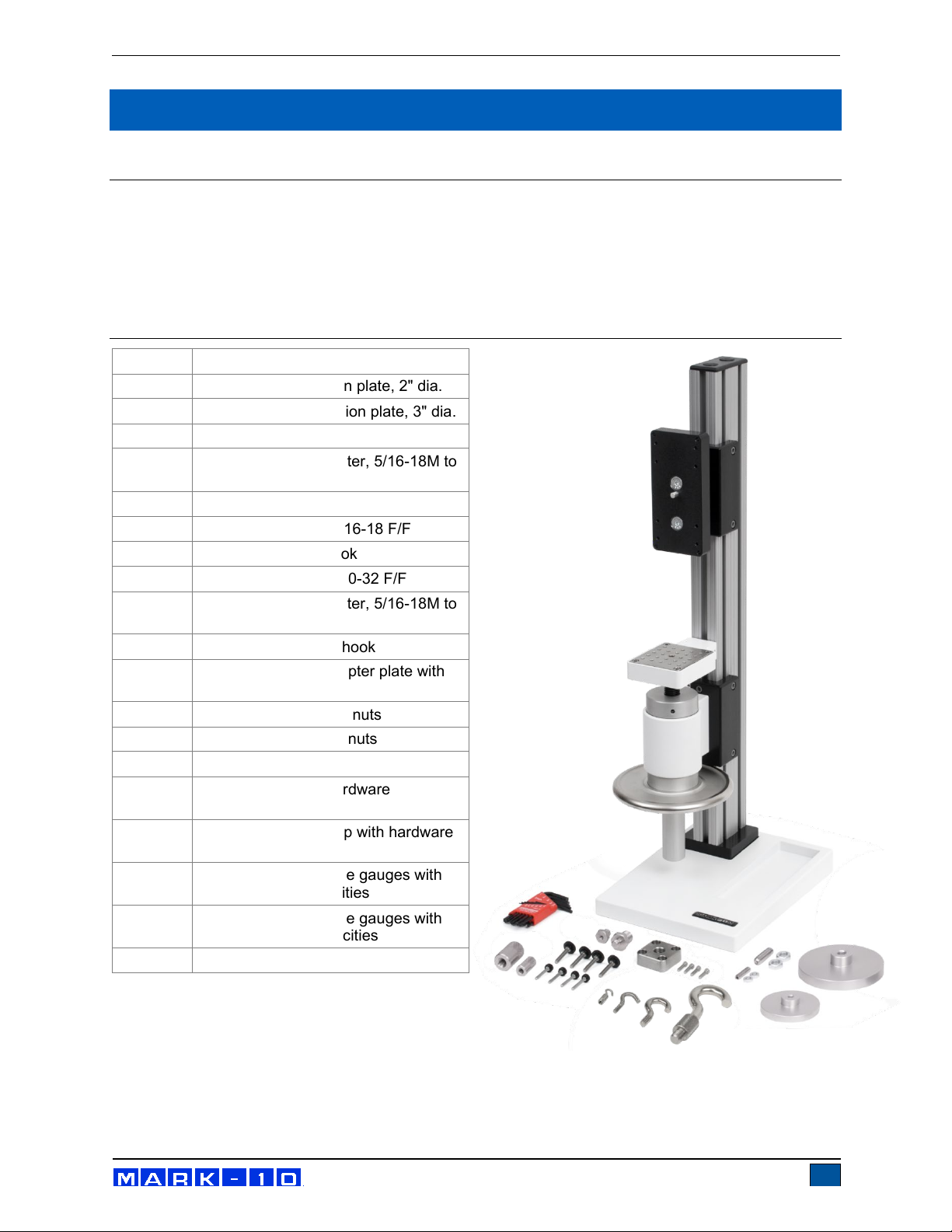
Quantity
Item
1
G1009 compression plate, 2" dia.
1
G1028 small hook
1
G1030 thread adapter, 5/16-18M to #10-32F
1
G1035 large hook
1
G1038 medium hook
1
G1041 thread adapter, 5/16-18M to #1/2-20M
1
G1042 extra large hook
1
G1091 thread coupler, 1/2-20F, 1/2-20F
1
5/16-18 stud with jam nuts
1
#10-32 stud with jam nuts
1
Wrench, 5/16-3/8
1
Base (Model TSA750)
2
Mounting leg with hardware (TSA750H)
Additional column cap with hardware
(TSA750H)
Thumb screw for force gauges with 0.12 - 500
lbF capacities
Thumb screw for force gauges with 750 - 2,000
lbF capacities
1
Allen wrench set
TSA750 / TSA750H
1 UNPACKING AND SETTING UP
1. Carefully unpack the stand and inspect for any damage. Check to make sure that you have received a
complete test stand with all accessories – see List of Included Items. Save original packaging
materials in case future transportation is required.
2. Install the loading lever. The position of the loading lever can be adjusted as required – see the
Operation section for your particular model.
3. Place the stand on a firm, flat and level working surface free from vibration to ensure accurate readings.
It is recommended that the test stand be secured to a work bench – see Operation section.
2 LIST OF INCLUDED ITEMS
1
4
4
Find Quality Products Online at: sales@GlobalTestSupply.com
www.GlobalTestSupply.com
Page 4

Series TS Manual Force Test Stands User’s Guide
3
Adjustable loading lever
3 OPERATION
1. Mount the test stand to a firm, flat, and level working surface for maximum
safety and accuracy using four 5/16 screws (not included). Use the included
mounting hole drill template to accurately drill the holes. Testing can take
place without securing the test stand in such a manner, however, it is strongly
recommended that the stand be secured, especially for large forces.
2. Install a force gauge onto the gauge plate with four thumb screws. Mark-10
force gauges mount directly to the stand without adapters.
3. Install any needed attachments, including grips, adapters, and other
materials necessary for your test sample. Make sure these items are set up
in a secure and safe manner.
4. Zero out the force gauge, then begin the test by rotating the lever clockwise
for compression or counter-clockwise for tension.
The loading lever can be adjusted to allow for ease of operation. Reposition the
loading lever by removing the knob and realigning the lever pin in the mounting
hub.
The rack brake can be set by loosening the wing nut, positioning the rack to the desired location and retightening the wing nut.
The clearance on the rack can be set by adjusting the four set screws using the tools provided.
The travel stops can be adjusted in 0.5” [12.7 mm] increments along the rack by moving the blocks to the
desired location and tightening two screws. Fine adjustments can be made using adjusting screws on the
housing and locking the jam nuts.
Note: To maintain smooth functioning of the stand, avoid overloads and repetitive shock loads.
3.1 Reversible Gauge Mounting Plate
The gauge mounting plate is reversible for compatibility with force gauges of
all capacities. Reverse the plate by removing two screws, then flip it around
and reinstall.
3.2 Optional Equipment
Digital Travel Display Kit
6" [150 mm] travel, 0.0005" [0.01 mm] resolution, SPC output for automated
data collection. Requires travel stops kit. To output data to a PC via USB,
use communication adapter part no. MU100 and 09-1066 cable.
Find Quality Products Online at: sales@GlobalTestSupply.com
www.GlobalTestSupply.com
Page 5

Series TS Manual Force Test Stands User’s Guide
4
Weight (test stand, only)
TSA750
TSA750H
4 DIMENSIONS in [mm]
5 SPECIFICATIONS
Maximum force 750 lbF [3.75 kN]
Maximum travel, with stops 3.75" [95 mm]
Maximum travel, without stops 6" [152 mm]
Travel rate 3" [76.2 mm] / lever revolution
TSA750: 6 lb [7.3 kg], TSA750H: 3 lb [5.9 kg]
Optional digital travel
display resolution
Find Quality Products Online at: sales@GlobalTestSupply.com
www.GlobalTestSupply.com
0.0005" [0.01 mm]
Page 6

Series TS Manual Force Test Stands User’s Guide
5
Quantity
Item
1
G1030 thread adapter, 5/16-18M to #10-32F
4
Thumb screw for force gauge
1
Allen wrench set
TSB100
1 UNPACKING AND SETTING-UP
1. Carefully unpack the stand and inspect for any damage. Check to make sure that you have received a
complete test stand with all accessories – see List of Included Items. Save original packaging
materials in case future transportation is required.
2. Install the loading lever. The position of the loading lever can be adjusted as required – see Operation
section.
3. Place the stand on a firm, flat and level working surface free from vibration to ensure accurate readings.
It is recommended that the test stand be secured to a work bench – see Operation section.
2 LIST OF INCLUDED ITEMS
Find Quality Products Online at: sales@GlobalTestSupply.com
www.GlobalTestSupply.com
Page 7

Series TS Manual Force Test Stands User’s Guide
6
Adjustable loading lever
3 OPERATION
1. Mount the test stand to a firm, flat, and level working surface for maximum
safety and accuracy using four 5/16 screws (not included). Use the included
mounting hole drill template to accurately drill the holes. Testing can take
place without securing the test stand in such a manner, however, it is
recommended that the stand be secured.
2. Install a force gauge onto the gauge plate with four thumb screws. Mark-10
force gauges mount directly to the stand without adapters.
3. Install any needed attachments, including grips, adapters, and other
materials necessary for your test sample. Make sure these items are set up
in a secure and safe manner.
4. Zero out the force gauge, then rotate the lever clockwise for tension or
counter-clockwise for compression.
The loading lever can be adjusted to allow for ease of operation. Reposition the
loading lever by removing the knob and realigning the lever pin in the mounting
hub.
The rack brake can be set by loosening the wing nut, positioning the rack to the desired location and retightening the wing nut.
The clearance on the rack can be adjusted by removing the gauge plate, aligning the C-bracket holes with
the set screws and adjusting as necessary.
Note: To maintain smooth functioning of the stand, avoid overloads and repetitive shock loads.
3.1 Optional Equipment
Digital Travel Display Kit
6" [150 mm] travel, 0.0005" [0.01 mm] resolution, SPC output for automated
data collection. Requires travel stops kit. To output data to a PC via USB,
use communication adapter part no. MU100 and 09-1066 cable.
Travel Stops Kit
The travel stops can be adjusted in 0.5” [12.7 mm] increments along the rack
by moving the blocks to the desired location and tightening two screws. Fine
adjustments can be made using adjusting screws on the housing and locking
the jam nuts.
Find Quality Products Online at: sales@GlobalTestSupply.com
www.GlobalTestSupply.com
Page 8

Series TS Manual Force Test Stands User’s Guide
7
Maximum travel, with stops
Maximum travel, without stops
Travel rate
display resolution
4 DIMENSIONS in [mm]
5 SPECIFICATIONS
Maximum force 100 lbF [500 N]
3.75" [95 mm]
6" [150 mm]
3" [76.2 mm] / lever revolution
Optional digital travel
0.0005" [0.01 mm]
Find Quality Products Online at: sales@GlobalTestSupply.com
www.GlobalTestSupply.com
Page 9
Series TS Manual Force Test Stands User’s Guide
8
Quantity
Item
1
G1009 – compression plate, 2" dia.
1
G1009-1 – compression plate, 3" dia.
1
G1028 – small hook
G1030 – thread adapter, 5/16-18M to
#10-32F
1
G1035 – large hook
1
G1037 – coupling, 5/16-18 F/F
1
G1038 – medium hook
1
G1039 – coupling, #10-32 F/F
G1041 – thread adapter, 5/16-18M to
#1/2-20M
1
G1042 – extra large hook
G1044 – 1/2-20F adapter plate with
mounting hardware
1
5/16-18 stud with jam nuts
1
#10-32 stud with jam nuts
1
Base (TSC1000H)
Mounting leg with hardware
(TSC1000H)
Additional column cap with hardware
(TSC1000H)
Thumb screw for force gauges with
0.12 - 500 lbF capacities
Thumb screw for force gauges with
750 - 2,000 lbF capacities
1
Allen wrench set
TSC1000 / TSC1000H
1 UNPACKING AND SETTING-UP
1. Carefully unpack the stand and inspect for any damage. Check to make sure that you have received a
complete test stand with all accessories – see List of Included Items. Save original packaging
materials in case future transportation is required.
2. Place the stand on a firm, flat and level working surface free from vibration to ensure accurate readings.
It is recommended that the test stand be secured to a work bench – see Operation section.
2 LIST OF INCLUDED ITEMS
1
1
1
2
1
4
4
Find Quality Products Online at: sales@GlobalTestSupply.com
www.GlobalTestSupply.com
Page 10

Series TS Manual Force Test Stands User’s Guide
9
display resolution
3 OPERATION
1. Mount the test stand to a firm, flat, and level working surface for maximum safety and accuracy using
four 5/16 screws (not included). Use the included mounting hole drill template to accurately drill the
holes (TSC1000, only). Testing can take place without securing the test stand in such a manner,
however, it is strongly recommended that the stand be secured, especially for large forces.
2. Install a force gauge onto the gauge plate with four thumb screws. Mark-10 force gauges mount directly
to the stand without adapters.
3. Install any needed attachments, including grips, adapters, and other materials necessary for your test
sample. Make sure these items are set up in a secure and safe manner.
4. Zero out the force gauge, then begin the test by turning the hand wheel clockwise for compression or
counter-clockwise for tension.
Note: To maintain smooth functioning of the stand, avoid overloads and repetitive shock loads.
3.1 Reversible Gauge Mounting Plate
The gauge mounting plate is reversible for compatibility with force gauges of all
capacities. Reverse the plate by removing two screws, then flip it around and
reinstall.
3.2 Optional Equipment
Digital Travel Display Kit
6" [150 mm] travel, 0.0005" [0.01 mm] resolution, SPC output for automated
data collection. Requires travel stops kit. To output data to a PC via USB, use
communication adapter part no. MU100 and 09-1066 cable.
4 SPECIFICATIONS
Maximum force
Maximum travel
Travel rate
Weight (test stand, only)
Optional digital travel
1,000 lb [5000 N]
3.5” [88.9 mm]
0.1” [2.54 mm] / handwheel rev.
TSC1000: 25 lb [9.0 kg]
TSC1000H: 20 lb [11.3 kg]
0.0005” [0.01 mm]
Find Quality Products Online at: sales@GlobalTestSupply.com
www.GlobalTestSupply.com
Page 11

Series TS Manual Force Test Stands User’s Guide
10
5 DIMENSIONS in [mm]
TSC1000
TSC1000H
Find Quality Products Online at: sales@GlobalTestSupply.com
www.GlobalTestSupply.com
Page 12

Series TS Manual Force Test Stands User’s Guide
11
Quantity
Item
1
G1009 – compression plate, 2" dia.
1
G1009-1 – compression plate, 3" dia.
1
G1028 – small hook
G1030 – thread adapter, 5/16-18M to
#10-32F
1
G1035 – large hook
1
G1037 – coupling, 5/16-18 F/F
1
G1038 – medium hook
1
G1039 – coupling, #10-32 F/F
G1041 – thread adapter, 5/16-18M to
#1/2-20M
1
G1042 – extra large hook
G1044 – 1/2-20F adapter plate with
mounting hardware
1
5/16-18 stud with jam nuts
1
#10-32 stud with jam nuts
1
Base (TSC1000H)
Mounting leg with hardware
(TSC1000H)
Additional column cap with hardware
(TSC1000H)
Thumb screw for force gauges with
0.12 - 500 lbF capacities
Thumb screw for force gauges with
750 - 2,000 lbF capacities
1
Allen wrench set
TSF / TSFH
1 UNPACKING AND SETTING-UP
1. Carefully unpack the stand and inspect for any damage. Check to make sure that you have received a
complete test stand with all accessories – see List of Included Items. Save original packaging
materials in case future transportation is required.
2. Place the stand on a firm, flat and level working surface free from vibration to ensure accurate readings.
It is recommended that the test stand be secured to a work bench – see Operation section.
2 LIST OF INCLUDED ITEMS
1
1
1
2
1
4
4
Find Quality Products Online at: sales@GlobalTestSupply.com
www.GlobalTestSupply.com
Page 13

Series TS Manual Force Test Stands User’s Guide
12
3 OPERATION
1. Mount the test stand to a firm, flat, and level working surface for maximum safety and accuracy using
four 5/16 screws (not included). Use the included mounting hole drill template to accurately drill the
holes. Testing can take place without securing the test stand in such a manner, however, it is strongly
recommended that the stand be secured, especially for large forces.
2. Install a force gauge onto the gauge plate with four thumb screws. All Mark-10 force gauges mount
directly to the stand without adapters.
3. Install any required attachments, including grips, adapters, and other materials necessary for your test
sample. Make sure these items are set up in a secure and safe manner.
4. Begin the test by turning the hand wheel clockwise for compression or counter-clockwise for tension.
The gauge bracket’s height can be adjusted along the column. Loosen the four screws that secure the
bracket to the column, adjust to the desired height, and retighten the screws.
Note: To maintain smooth operation of the test stand, avoid overloads and repetitive shock loads.
3.1 Reversible Gauge Mounting Plate
The gauge mounting plate is reversible for compatibility with force gauges of
all capacities. Reverse the plate by removing two screws, then flip it around
and reinstall.
3.2 Optional Equipment
Digital Travel Display Kit
6" [150 mm] travel, 0.0005" [0.01 mm] resolution, SPC output for automated
data collection. Requires travel stops kit. To output data to a PC via USB,
use communication adapter part no. MU100 and 09-1066 cable.
4 SPECIFICATIONS
Maximum force
Maximum travel
Travel rate
Weight (test stand, only)
Optional digital travel
display resolution
1,000 lb [5,000 N]
4" [102 mm]
0.013" [0.34 mm] / handwheel rev.
TSF: 33 lb [14.5 kg]
TSFH: 27 lb [12.3 kg]
0.0005” [0.01 mm]
Find Quality Products Online at: sales@GlobalTestSupply.com
www.GlobalTestSupply.com
Page 14

Series TS Manual Force Test Stands User’s Guide
13
TSF
TSFH
5 DIMENSIONS in [mm]
Find Quality Products Online at: sales@GlobalTestSupply.com
www.GlobalTestSupply.com
 Loading...