

Page 1

Models:
TABLE OF CONTENTS
F105 | F305 | F505 | F505H
F755 | F755S | F1505 | F1505S
®
IntelliMESUR
Software
Series F
TEST FRAMES
User’s Guide
Find Quality Products Online at: sales@GlobalTestSupply.com
www.GlobalTestSupply.com
Page 2

Series F Test Frames + IntelliMESUR® Software User’s Guide
2
TOC
TABLE OF CONTENTS
TABLE OF CONTENTS ......................................................................................................... 1
1 OVERVIEW .............................................................................................................................. 3
1.1 Intended purpose ............................................................................................................. 4
1.2 Models F105 / F305 / F505 / F505H ................................................................................ 4
1.3 Models F755 / F755S / F1505 / F1505S ......................................................................... 6
2 SAFETY ................................................................................................................................... 8
2.1 Checks and procedures ................................................................................................... 8
2.2 Connecting power ............................................................................................................ 9
2.3 Emergency Stop .............................................................................................................. 9
3 SETUP ................................................................................................................................... 10
3.1 Intended Use .................................................................................................................. 10
3.2 Moving the frame into position ....................................................................................... 10
3.3 Mounting and placement ............................................................................................... 10
3.4 Limit switches ................................................................................................................. 10
3.5 Connections and outputs ............................................................................................... 11
3.6 Installing Series FS05 Force Sensors to Models F105 / F305 / F505 / F505H ............. 12
3.7 Installing Series R07 Force Sensors to Models F755 / F755S / F1505 / F1505S ......... 13
3.8 Installing Series FS05 Force Sensors to Models F755 / F755S / F1505 / F1505S ....... 13
3.9 Installing a Third-Party Force Sensor ............................................................................ 14
3.10 Installing the IntelliMESUR control panel .................................................................... 15
4 INSTALLING INTELLIMESUR .............................................................................................. 16
4.1 Hardware Requirements ................................................................................................ 16
4.2 Installation ...................................................................................................................... 17
5 INTELLIMESUR BASICS ...................................................................................................... 18
5.1 Opening IntelliMESUR ................................................................................................... 18
5.2 Home Screen ................................................................................................................. 19
6 SETTINGS ............................................................................................................................. 21
6.1 Information ..................................................................................................................... 21
6.2 User Management ......................................................................................................... 22
6.3 Calibration ...................................................................................................................... 24
6.4 Preferences .................................................................................................................... 24
6.5 Optional Functions ......................................................................................................... 26
6.6 Overloads ....................................................................................................................... 27
6.7 Deflection Compensation ............................................................................................... 27
6.8 Update Software and Update Firmware ........................................................................ 27
7 MANUAL CONTROL ............................................................................................................. 28
7.1 Load and Distance Measurement .................................................................................. 29
7.2 Motion Control Modes .................................................................................................... 29
7.3 Height / Length Offset .................................................................................................... 30
Find Quality Products Online at: sales@GlobalTestSupply.com
www.GlobalTestSupply.com
Page 3

Series F Test Frames + IntelliMESUR® Software User’s Guide
3
TOC
7.4 Set Home ....................................................................................................................... 31
8 CREATING A BASIC TEST .................................................................................................. 31
8.1 Load Limit ...................................................................................................................... 31
8.2 Distance Limit ................................................................................................................ 42
8.3 Break Limit ..................................................................................................................... 43
8.4 Load Hold ....................................................................................................................... 43
8.5 Cycle Test ...................................................................................................................... 43
8.6 COF Test ....................................................................................................................... 46
9 CREATING A MULTI-STEP TEST ........................................................................................ 48
9.1 Multi-Step Overview ....................................................................................................... 48
9.2 Step Types ..................................................................................................................... 50
10 RUNNING A TEST ............................................................................................................... 53
10.1 Favorite Tests .............................................................................................................. 53
10.3 Results View ................................................................................................................ 58
10.4 Data Details View......................................................................................................... 62
10.5 Creating a Report......................................................................................................... 63
10.6 Recalling Previous Data .............................................................................................. 66
11 CALIBRATION .................................................................................................................... 66
11.1 Force Sensor Calibration ............................................................................................. 66
11.2 Speed and Distance Calibration .................................................................................. 71
11.3 Test Frame Deflection Compensation ......................................................................... 71
12 MAINTENANCE & SERVICE – MODELS F105 / F305 / F505 / F505H ............................. 72
12.1 Physical Maintenance .................................................................................................. 72
12.2 Removing the Motor Drive Unit (MDU) ........................................................................ 76
13 MAINTENANCE & SERVICE – MODELS F1505 / F1505S / F755 / F755S ....................... 77
13.1 Physical Maintenance .................................................................................................. 77
13.2 Removing the Motor Drive Unit (MDU) ........................................................................ 79
14 ACCESSORY INSTALLATION ........................................................................................... 80
14.1 Shield Installation ......................................................................................................... 80
14.2 Separating the Column From The Base / Column Extension Installation – F105 / F305 / F505 /
F505H .................................................................................................................................. 83
14.3 Installing a double column extension – F105 / F305 / F505 ................................... 86
15 UPDATING SOFTWARE AND FIRMWARE ....................................................................... 87
16 SPECIFICATIONS & DIMENSIONS ................................................................................... 88
16.1 Specifications ............................................................................................................... 88
16.2 Dimensions .................................................................................................................. 89
Find Quality Products Online at: sales@GlobalTestSupply.com
www.GlobalTestSupply.com
Page 4

Series F Test Frames + IntelliMESUR® Software User’s Guide
4
TOC
Qty.
Description
1
Control panel, mounting bracket, and hardware (-IMT models only)
1
Mounting bracket, column end (F505H only)
1
USB flash drive containing software installation files (-IM models only)
1
USB dongle (-IM models only)
1
USB cable
-IM models: A to B
Accessories kit:
- Allen wrench set
1
Power cord
1
Allen wrench set
1 OVERVIEW
1.1 Intended purpose
Series F test frames produce tension and compression forces. When combined with a force sensor and
IntelliMESUR software, users can measure force and distance, set up a test, record, analyze, and output
data. Test frames are offered in several models, corresponding to different heights and force ranges.
Series FS05 or Series R07 force sensors are required for use with these test frames.
IntelliMESUR software is required to run Series F test frames and extract force and distance data from
the test frame and force sensor. IntelliMESUR is offered pre-configured on a tablet with mounting bracket,
or as a standalone software application which may be installed on the user’s device.
1.2 Models F105 / F305 / F505 / F505H
1.2.1 Included items
-IMT models: right-angle C to B
- #10-32M medium hook
- 5/16-18M large hook
- #10-32F 2” diameter compression plate
1
Find Quality Products Online at: sales@GlobalTestSupply.com
- #10-32 M/F 2” extension rod
- #10-32 F/F coupler
- Adapter, 5/16-18M to #10-32F
- Set screw, #10-32 x 3/4" (1)
- Hex nut, #10-32 (2)
www.GlobalTestSupply.com
Page 5
Series F Test Frames + IntelliMESUR® Software User’s Guide
5
TOC
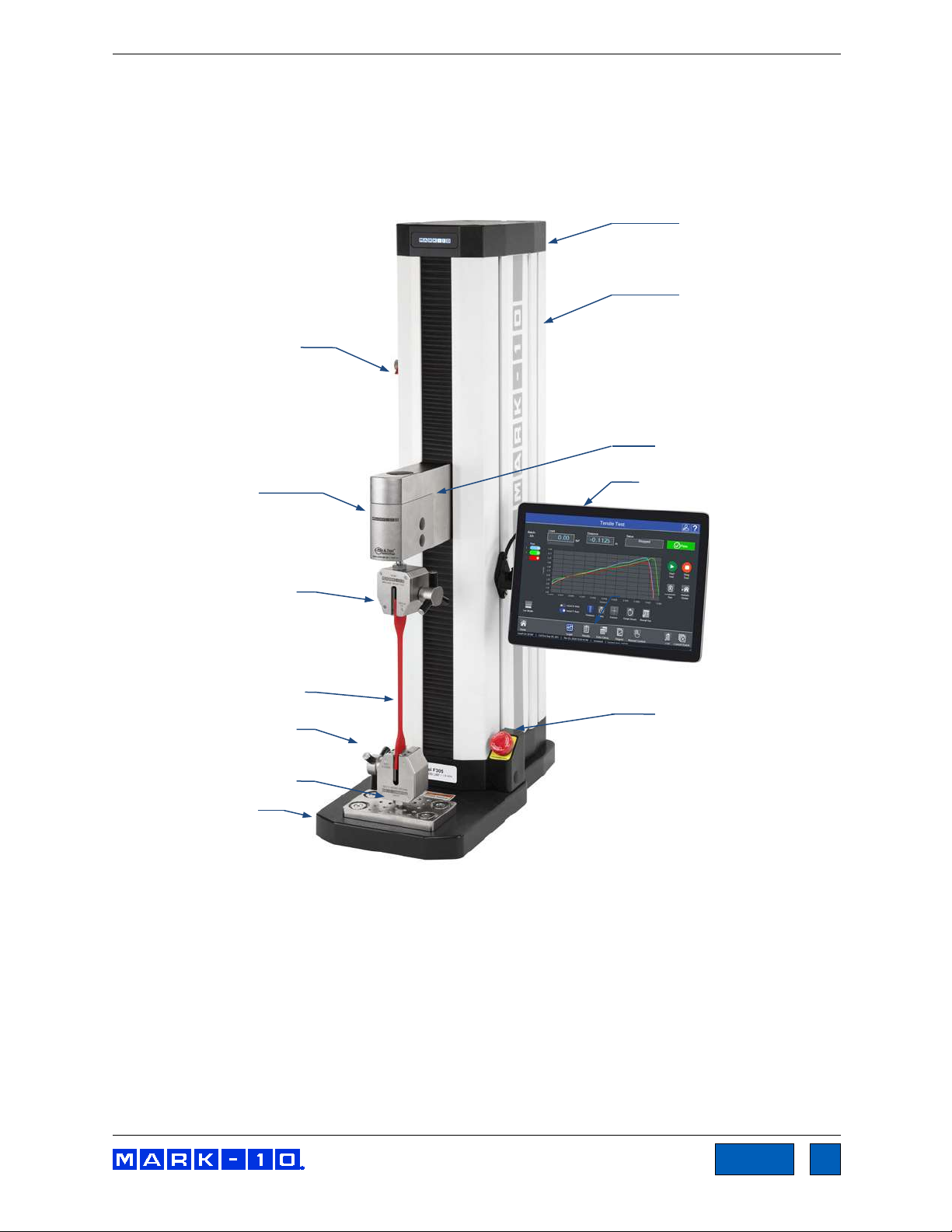
Base
Base plate
Lower grip
Upper grip
Force
sensor
Column
Tablet control
panel
Emergency
stop
Upper limit
visible)
Test sample
Crosshead
Column
cap
1.2.2 Physical features
Note the following physical features. The user’s guide will reference this terminology. Model F305-IMT is
shown below:
switch
(lower limit
switch not
Find Quality Products Online at: sales@GlobalTestSupply.com
www.GlobalTestSupply.com
Page 6

Series F Test Frames + IntelliMESUR® Software User’s Guide
6
TOC
Qty.
Description
1
Control panel, mounting bracket, and hardware (-IMT models only)
1
USB flash drive containing software installation files (-IM models only)
1
USB dongle (-IM models only)
1
USB cable
-IM models: A to B
1
Eye end kit for base
2
Lock ring for eye end
2
Spanner wrench
1
Power cord
1
Allen wrench set
1.2.3 Installing the Column End Cap for F505H
The end cap is shipped in a separate box within the main box for the F505H test frame. Line it up with the
right end of the column, then install with the four included screws, as shown below:
1.3 Models F755 / F755S / F1505 / F1505S
1.3.1 Included items
-IMT models: right-angle C to B
Find Quality Products Online at: sales@GlobalTestSupply.com
www.GlobalTestSupply.com
Page 7

Series F Test Frames + IntelliMESUR® Software User’s Guide
7
TOC
Base
Base plate
Lower grip
Upper grip
Force sensor
Column
Bellows
Control panel
Emergency stop
Limit
(not visible)
Test sample
Crosshead
Column cap
Control panel
bracket
1.3.2 Physical features
Note the following physical features. The user’s guide will reference this terminology. Model F1505-IMT is
shown below:
switches
www.GlobalTestSupply.com
Find Quality Products Online at: sales@GlobalTestSupply.com
Page 8

Series F Test Frames + IntelliMESUR® Software User’s Guide
8
TOC
2 SAFETY
Safety features provided by Series F test frames may be impaired if equipment is used in a
manner not specified by Mark-10.
2.1 Checks and procedures
The following safety checks and procedures should be performed before and during operation:
1. Always consider the characteristics of the sample being tested before initiating a test. A risk
assessment should be carried out beforehand to ensure that all safety measures have been
addressed and implemented.
2. Wear eye and face protection when testing, especially when testing brittle samples that have the
potential to shatter under force. Be aware of the dangers posed by potential energy that can
accumulate in the sample during testing. Extra bodily protection should be worn if a destructive
failure of a test sample is possible.
3. Keep away from moving parts of the test frame. Loose articles of clothing should not be worn.
Long hair should be covered to avoid a hazardous situation. A Crush Hazard warning label is
located on the base of the test frame. It appears as follows:
Definition: Keep any body parts and clothing clear of the area between the base of the test frame and the
moving crosshead.
4. Ensure that grips and fixtures are positioned to ensure axial load with respect to the load axis of
the force sensor.
slipping out during a test, which is a safety risk to the operator and others in the vicinity. If using a
grip or fixture from a supplier other than Mark-10, ensure that it is constructed of suitably rugged
materials and components.
5. In those applications where samples can shatter, or other applications that could lead to a
hazardous situation, use of a shield is strongly recommended.
6. When the test frame is not in use, ensure that the power is turned off to prevent accidental
engagement of any of the controls.
Ensure that they secure the sample in such a way that it is prevented from
Find Quality Products Online at: sales@GlobalTestSupply.com
www.GlobalTestSupply.com
Page 9

Series F Test Frames + IntelliMESUR® Software User’s Guide
9
TOC
2.2 Connecting power
Plug one end of the power cord into its receptacle at the rear of the stand and the other end into a wall
outlet with local earth ground (3-prong connector).
Before turning on power, the following safety checks and procedures should be performed:
1. Never operate the test frame if there is any visible damage to the power cord or the test frame
itself. The test frame is powered by 110V/220V. Any contact with this high voltage can cause
serious injury or even death.
2. Ensure that the test frame is kept away from water or any electrically conductive liquids at all
times.
3. Make sure the electrical outlet powering the test frame has local earth ground (3-prong
connector).
4. The test frame should be serviced by a trained technician only. Power must be disconnected
before the column covers are removed.
5. Never use a detachable mains supply cord with inadequate ratings.
After the above safety checks and procedures have been performed, the test frame may be powered on
and is ready for operation.
2.3 Emergency Stop
The emergency stop switch is located where the lower right end of the column is attached to the base, as
shown below:
Models F105 / F305 / F505 / F505H Models F755 / F755S / F1505 / F1505S
Press down to stop crosshead motion. Rotate clockwise to release the switch.
Find Quality Products Online at: sales@GlobalTestSupply.com
www.GlobalTestSupply.com
Page 10

Series F Test Frames + IntelliMESUR® Software User’s Guide
10
TOC
3 SETUP
3.1 Intended Use
Series F test frames with IntelliMESUR software are designed for tension and compression force
measurement applications. The test frame applies force, while a force sensor measures the applied
forces. IntelliMESUR software displays force and position information, and includes analytical tools to
help quality control, engineering, and manufacturing professionals determine the mechanical properties
and quality of their samples.
3.2 Moving the frame into position
Place the frame on a sturdy, clean, and level work area free from vibration.
In Models F755, F755S, F1505, and F1505S, a recessed lifting hook is located at the top of the column,
for ease of lifting, as shown below:
For Models F105, F305, F505, and F505H frames, orient the rear of the test frame towards the edge of a
table, tilt backwards, then lift underneath the base and underneath the rear of the column.
3.3 Mounting and placement
Place the test frame on a clean, flat and level work area free from vibration. Ensure that the rear of the
column is easily accessible, so that the power cord can be disconnected in an emergency.
It is suggested to mount the test frame to a work bench via screws fastened into the underside of the
base. Failure to properly mount the test frame may make it more vulnerable to tipping, especially if a
column extension is used, causing a hazardous situation.
3.4 Limit switches
Upper and lower limit switches are supplied to stop travel in both directions. They may be moved
up and down by loosening and tightening the thumb screws, as shown at left.
A dual-graduated inch/mm ruler adjacent to the limit switches can be helpful for positioning.
Find Quality Products Online at: sales@GlobalTestSupply.com
www.GlobalTestSupply.com
Page 11

Series F Test Frames + IntelliMESUR® Software User’s Guide
11
TOC
Auxiliary Limits
3.5 Connections and outputs
The following connections and outputs are supplied in the rear of the test frame, as shown in the
illustration below:
For interfacing an external limit switch, such as an interlock for a
shield door. A pin diagram is shown in the next sub-section.
USB port
For interfacing with a Windows device running IntelliMESUR.
Control Panel
Inactive.
External Emergency Switch
May be used to connect an optional external emergency stop
switch. May be installed at the factory at time of order, or installed
in the field as a retrofit. Required for use with optional shields.
Refer to the Accessory Installation section for instructions.
Power switch
Refer to the Connecting Power sub-section for important safety
information.
Power plug receptacle
Plug the power cord in here. Refer to the Connecting Power
sub-section for important safety information.
3.5.1 Auxiliary Limits pin diagram
Note that when pins 3 and 4 are not connected, the auxiliary limits are inactive.
is connected to either pin 3 or pin 4, the respective limit becomes active and the crosshead is prevented
from movement in that direction.
When the +5V from pin 2
Find Quality Products Online at: sales@GlobalTestSupply.com
www.GlobalTestSupply.com
Page 12

Series F Test Frames + IntelliMESUR® Software User’s Guide
12
TOC
3.6 Installing Series FS05 Force Sensors to Models F105 / F305 / F505 / F505H
Series FS05 force sensors mount directly to the crosshead. Once the test frame is in a stable and secure
position, install the force sensor by matching the gold-plated pads on the top surface with the pins in the
underside of the crosshead, as shown below:
While holding the force sensor in place with one hand, use an Allen wrench with the other hand to tighten
the screw that joins the force sensor to the crosshead, as shown below:
To avoid overload and damage, select a force sensor with sufficient capacity to
accommodate the application.
Optionally cover the screw head with the included black plastic cap.
Find Quality Products Online at: sales@GlobalTestSupply.com
www.GlobalTestSupply.com
Page 13

Series F Test Frames + IntelliMESUR® Software User’s Guide
13
TOC
Grips and fixtures may be threaded onto the threaded shaft protruding from the bottom of the force
sensor, for example:
3.7 Installing Series R07 Force Sensors to Models F755 / F755S / F1505 / F1505S
Install the sensor to the underside of the crosshead using the supplied socket head screw and hardware.
Plug the connector into the receptacle in the top front surface of the crosshead, then fasten the thumb
screws into the crosshead, as shown below:
Grips and fixtures may be threaded onto the underside of the sensor.
3.8 Installing Series FS05 Force Sensors to Models F755 / F755S / F1505 / F1505S
To avoid damage to the internal load cell or shaft, do not use tools to tighten grips or
attachments onto the shaft. Hand-tighten only.
Series FS05 force sensors may be installed via the optional AC1083 adapter, as shown below:
Find Quality Products Online at: sales@GlobalTestSupply.com
www.GlobalTestSupply.com
Page 14

Series F Test Frames + IntelliMESUR® Software User’s Guide
14
TOC
3.9 Installing a Third-Party Force Sensor
3.9.1 Models F105 / F305 / F505 / F505H
Using the optional Model PTAF adapter, a third-party force sensor may be mounted to the test frame.
Insert a screw of sufficient length and appropriate thread size through the crosshead, through the PTAF,
and into the force sensor, as shown in the following example:
3.9.2 Models F755 / F755S / F1505 / F1505S
Before installing the sensor, refer to the Model PTA / PTAF user’s guide for complete
instructions.
Using the optional Model PTAF adapter and AC1083 adapter, a third-party force sensor cell may be
mounted to the test frame. Insert a screw of sufficient length and appropriate thread size through the
crosshead, through the AC1083 adapter, through the PTAF, and into the force sensor, as shown in the
following example:
Find Quality Products Online at: sales@GlobalTestSupply.com
www.GlobalTestSupply.com
Page 15

Series F Test Frames + IntelliMESUR® Software User’s Guide
15
TOC
3.10 Installing the IntelliMESUR control panel
For test frame part numbers ending in “-IMT”, for example Model F305-IMT, a Windows tablet with
attached ball mount and mounting bracket are included, packaged separately.
The mounting arm is pre-installed into the front right slot in the test frame column via two screws, as
shown below:
Loosen the knob sufficiently to slide the ball, mounted to the rear of the tablet, into the arm. Orient the
tablet horizontally, with the USB-C port positioned on the left side. Adjust the viewing angle as desired,
then tighten the knob.
Do not attempt to adjust the viewing angle before loosening the knob.
Connect the included USB cable between the USB-C port and the USB-B port in the rear of column, and
connect the AC adapter connector, as shown below:
Plug in the AC adapter and press the Power button, in the lower right corner of the tablet. The tablet will
boot up directly into the IntelliMESUR application. If not, select the IntelliMESUR icon in the Windows
home screen.
Find Quality Products Online at: sales@GlobalTestSupply.com
www.GlobalTestSupply.com
Page 16

Series F Test Frames + IntelliMESUR® Software User’s Guide
16
TOC
4 INSTALLING INTELLIMESUR
4.1 Hardware Requirements
4.1.1 Pre-configured tablet
IntelliMESUR is pre-installed onto the tablet provided with “-IMT” model numbers, ex. F305-IMT.
4.1.2 User device installation
For model numbers ending in “-IM”, a separate license is provided to install onto the user’s device,
provided it meets the following specifications:
- Windows 10 or later operating system
- Minimum 4GB RAM
- Minimum monitor resolution of 1310 x 885
- Minimum of two USB ports (one for a dongle, one for a cable to the test frame)
To ensure optimal performance for IntelliMESUR, do not install any additional applications
onto the tablet.
Find Quality Products Online at: sales@GlobalTestSupply.com
www.GlobalTestSupply.com
Page 17

Series F Test Frames + IntelliMESUR® Software User’s Guide
17
TOC
4.2 Installation
Windows Administrator privileges are required to install IntelliMESUR.
1. Insert the installation flash drive into the device’s USB port, or download the zipped installation
folder. Locate and double-click the file “setup.exe”. The screen appears as follows:
2. Accept the terms, then click Install. All required files will be installed, including the Mark-10 USB
driver. When installation is complete, the screen appears as follows:
3. Click Finish and run IntelliMESUR.
Find Quality Products Online at: sales@GlobalTestSupply.com
www.GlobalTestSupply.com
Page 18

Series F Test Frames + IntelliMESUR® Software User’s Guide
18
TOC
5 INTELLIMESUR BASICS
5.1 Opening IntelliMESUR
Ensure that the device is connected to the test frame with a USB cable. Then open IntelliMESUR.
5.1.1 Mark-10-supplied tablet
Press the Power button. The tablet will boot directly into IntelliMESUR. If the tablet was asleep or
hibernating, double-tap the IntelliMESUR icon.
5.1.2 Customer-supplied Windows device
1. Insert the dongle into a USB port, as shown below:
The dongle contains a one-seat license. It must be plugged in at all times to run IntelliMESUR. To
run IntelliMESUR on a different device, install the application, then move the dongle to that
device.
2. Double-tap or double-click the IntelliMESUR icon.
If the dongle is not installed, IntelliMESUR prompts a message asking if you would like to use a
90-day trial. Make the appropriate selection. The trial is fully functional, and allows full use.
3. After plugging in the dongle or starting the trial, a login screen will appear as follows, if User
Login is enabled:
Otherwise, IntelliMESUR opens directly to the Home screen.
Find Quality Products Online at: sales@GlobalTestSupply.com
www.GlobalTestSupply.com
Page 19

Series F Test Frames + IntelliMESUR® Software User’s Guide
19
TOC
5.2 Home Screen
IntelliMESUR launches into the Home Screen, with the following selections:
Open Test
Recall a previously saved test.
New Test
Create a new test.
Edit Test
Edit the parameters of a previously saved test.
Recall Test Data
Recall data from previously saved test runs.
Settings
Includes preferences, calibration, overload log, and other functions.
Manual Control
Manually control the up and down motion of the test frame, and see live load, peak load,
and live distance.
Find Quality Products Online at: sales@GlobalTestSupply.com
www.GlobalTestSupply.com
Page 20

Series F Test Frames + IntelliMESUR® Software User’s Guide
20
TOC
Lower Footer
Within the lower footer, note the following selections:
Home
This icon is present in most screens, and links back to the Home screen.
Reconnect
If the test frame has been disconnected, then reconnected, select this button to restore
communication.
Exit
Select to exit the software. If running IntelliMESUR on a Mark-10-supplied tablet, a prompt will
offer the user two choices:
- Exit into Windows
- Exit and shut down the tablet
Bottom Footer
Along the bottom edge of all IntelliMESUR screens, the following information is always displayed, from
left to right:
- Force sensor capacity or “Test Frame Not Connected” message
- Connection status of the test frame
- Calibration status of the force sensor
- Date and time
- License / demo time status (see following section)
- Current user
Question Mark
Select this button at any time to be directed to the PDF User’s Guide.
5.1.3 90-day trial
IntelliMESUR can be run as a 90-day fully-functional trial, without a license. The number of days
remaining is indicated when launching the application, and can be viewed at any time in the Information
screen or the bottom footer, visible at all times:
Optional functions may be evaluated for 90 days. If an evaluation is in progress, the number of remaining
days is shown in the bottom footer:
Find Quality Products Online at: sales@GlobalTestSupply.com
www.GlobalTestSupply.com
Page 21
Series F Test Frames + IntelliMESUR® Software User’s Guide
21
TOC
6 SETTINGS
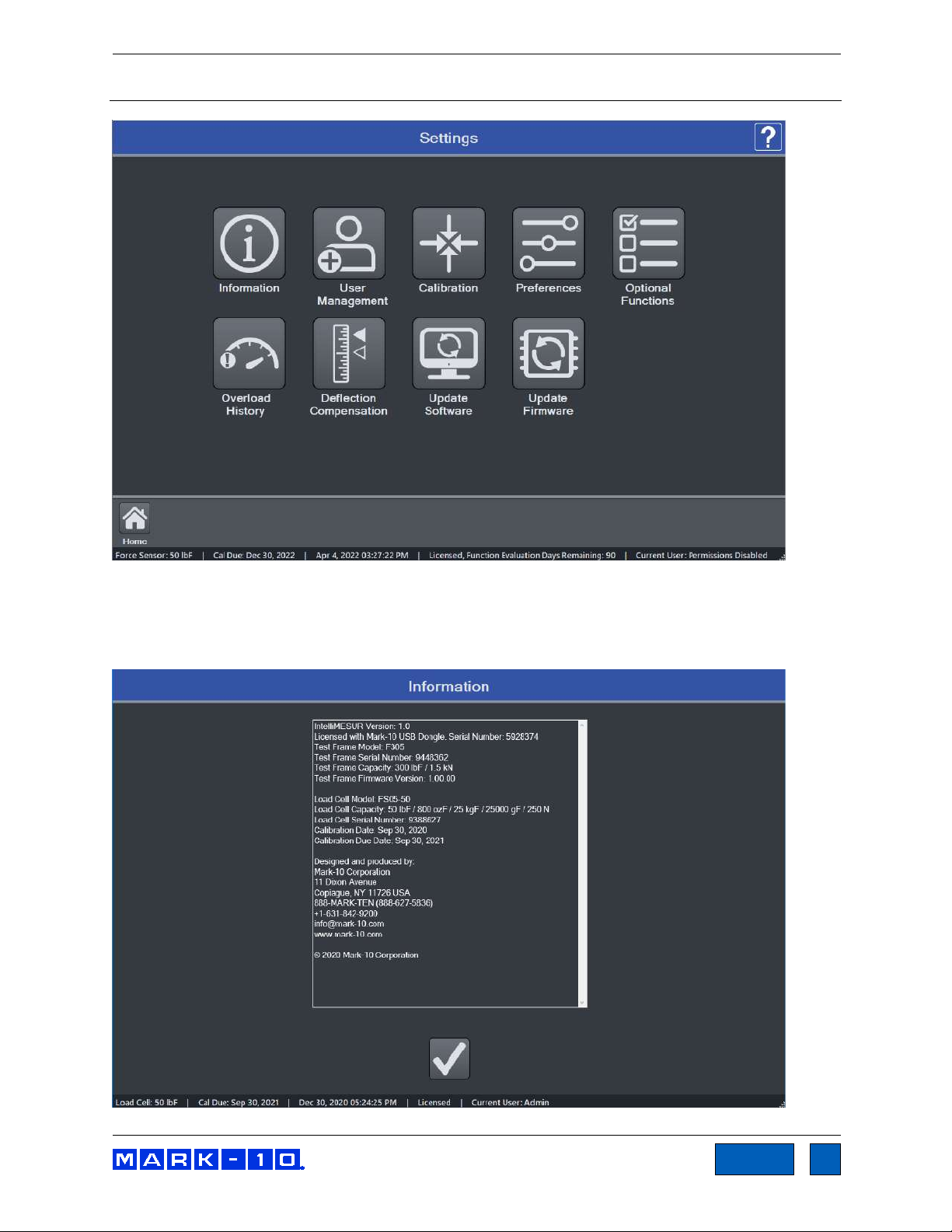
6.1 Information
Contains serial numbers, software and firmware versions, and other information about the equipment.
The screen appears as follows:
Find Quality Products Online at: sales@GlobalTestSupply.com
www.GlobalTestSupply.com
Page 22

Series F Test Frames + IntelliMESUR® Software User’s Guide
22
TOC
Operator
Supervisor
Administrator
Manual Control
X X X
Recall and run a test
X X X
Create a test X
X
Create a report
X X X
Calibration X
X
Update software
X
User management
X
6.2 User Management
6.2.1 Enabling User Login
IntelliMESUR can be run with or without a user login. By default, User Login is not enabled. Make the
appropriate selection in the following screen:
When User Login is enabled, the User Login button is always present in the upper corner of the screen,
as follows:
Select this button to log out and log in as a new user.
6.2.2 User Permission Levels
IntelliMESUR provides three user permission levels, summarized as follows:
User name Admin is pre-installed, with Administrator level access. The default password is admin, and may be changed if desired. Refer to the following sections for instructions.
Find Quality Products Online at: sales@GlobalTestSupply.com
www.GlobalTestSupply.com
Page 23

Series F Test Frames + IntelliMESUR® Software User’s Guide
23
TOC
6.2.3 Adding a User
Select Add User. The screen appears as follows:
Specify the user name, type, and password, then select Add User.
To modify a user, select Modify User. The screen appears as follows:
Select the user, then modify the user type, change the password, and/or delete the user. Note that the
user Admin cannot be deleted.
To change the password, select Change Password. The screen appears as follows:
Optionally select Show Password to view the passwords.
Find Quality Products Online at: sales@GlobalTestSupply.com
www.GlobalTestSupply.com
Page 24

Series F Test Frames + IntelliMESUR® Software User’s Guide
24
TOC
Enter the requested passwords. If the password has been forgotten, select Forgot Password. The
screen appears as follows:
IntelliMESUR automatically generates a request code. Supply this code to Mark-10 or a distributor, who
will then provide a corresponding authorization code, which allow the user to reset the password.
6.3 Calibration
Refer to the Calibration section for instructions on calibrating a force sensor.
6.4 Preferences
Default units of measure, date and time format, and other settings may be accessed from the Preferences
screen. Select Settings, then Preferences.
Find Quality Products Online at: sales@GlobalTestSupply.com
www.GlobalTestSupply.com
Page 25

Series F Test Frames + IntelliMESUR® Software User’s Guide
25
TOC
Default Settings
Load and Distance Units
Select the desired units of measure. Note that not all units are supported by all force sensors. Refer to the
force sensor’s specifications for list of supported units.
Digital Filter
The digital filter smooths out load readings in situations where there is mechanical interference in the
work area or test sample. The filter utilizes a moving average technique in which consecutive readings
are pushed through a buffer and the displayed reading is the average of the buffer contents. By varying
the length of the buffer, a variable smoothing effect can be achieved. The selection of 1 will disable the
filter since the average of a single value is the value itself.
Available settings: 1 through 16,384.
It is recommended to keep the filter as low as possible for best performance.
Default Folders
Select the corresponding Open buttons to browse to the desired folder locations for test configuration
files, data, results, and reports.
All above file types created by IntelliMESUR are encrypted, for data integrity purposes, except .csv file
exports.
Date and Time Format
Select the desired date and time format.
The current date and time are linked to the Windows clock. To change the time on a touch-enabled
device, press and hold the clock in the lower-right corner of the screen. If using a mouse, right-click, then
select Adjust date/time. The time is displayed along the lower edge of the IntelliMESUR screen.
Note: if the device is not connected to the internet, the Windows clock may drift by up to several minutes
per year.
Find Quality Products Online at: sales@GlobalTestSupply.com
www.GlobalTestSupply.com
Page 26

Series F Test Frames + IntelliMESUR® Software User’s Guide
26
TOC
6.5 Optional Functions
A number of optional software functions are available within IntelliMESUR
means of evaluating optional functions for 90 days, and activating these options permanently.
®
. This section provides a
Activating a Function
To activate an optional function, select the desired function. Then, provide Mark-10 with the Test Frame
Serial Number or Licensing Dongle Serial Number. Mark-10 will supply a corresponding Activation Code.
Enter this code into the provided space, then select Activate to permanently enable the function.
Functions may also be evaluated for 90 days. Select Start to initialize the evaluation period. During this
period, “Evaluation Mode” will appear above the list of functions. A function may be activated at any time
before, during, or after the evaluation period.
Find Quality Products Online at: sales@GlobalTestSupply.com
www.GlobalTestSupply.com
Page 27

Series F Test Frames + IntelliMESUR® Software User’s Guide
27
TOC
6.6 Overloads
IntelliMESUR constantly monitors the force sensor, and stops the crosshead when the load reaches
120% of capacity. However, it is still possible to overload a force sensor when it is stationary by manually
applying excessive force to it.
Overload History provides a record of the 50 most recent overloads, containing a time stamp, motion
direction, and force direction for each occurrence. An example screen appears as follows:
Note: Overloads which may occur while the force sensor is disconnected from a Series F test frame, or
while the test frame is powered off, are not recorded in Overload History.
6.7 Deflection Compensation
Refer to the Calibration section for further information.
6.8 Update Software and Update Firmware
Refer to the Maintenance and Service section for further information.
Find Quality Products Online at: sales@GlobalTestSupply.com
www.GlobalTestSupply.com
Page 28

Series F Test Frames + IntelliMESUR® Software User’s Guide
28
TOC
7 MANUAL CONTROL
Manual Control allows the user to move the crosshead up and down and observe force and distance
data, without creating a test. Manual control is useful when needing to manually adjust the crosshead
prior to starting a test, and also provides a means of creating a reference point for Height Mode.
Note: Data cannot be saved in Manual Control.
The screen appears as follows:
Find Quality Products Online at: sales@GlobalTestSupply.com
www.GlobalTestSupply.com
Page 29

Series F Test Frames + IntelliMESUR® Software User’s Guide
29
TOC
7.1 Load and Distance Measurement
Load and distance measurement are displayed as below:
Load
Load is displayed in the unit of measurement selected in Default Settings. Use the Mode button to
toggle between three display modes:
Load
The real-time load.
Peak Compression Load
Maximum observed compression load.
Peak Tension Load
Maximum observed tension load.
The load bar below the load reading indicates when approaching an overload. The bar increases
to the right for compression readings, and to the left for tension readings. The bar colors are as
follows:
Green 0 - 80% of force sensor capacity
Yellow 80 to 100% of force sensor capacity
Red 100+% of force sensor capacity
At 110% of force sensor capacity, the load reading is replaced by the word, “OVER”, which
indicates an overload. The status window background color turns red.
Load Zero zeroes the live load and clears the peaks.
Distance Zero zeroes the distance.
7.2 Motion Control Modes
Jog Mode
The crosshead moves the specified distance each time Up or Down is selected. Three pre-sets
are available, as shown below:
Find Quality Products Online at: sales@GlobalTestSupply.com
www.GlobalTestSupply.com
Page 30

Series F Test Frames + IntelliMESUR® Software User’s Guide
30
TOC
Select the desired preset. Select Edit to change the jog distance for the corresponding preset.
Momentary Mode
The crosshead will move only while selecting and holding down the Up or Down button. To set
the speed, type the value into the box or drag the slider to the desired value, as shown below:
Maintained Mode
The crosshead will move continuously after selecting the Up or Down button. Set the speed in
the same manner as Momentary Mode.
®
FollowMe
Mode
The crosshead responds to pushing or pulling on the force sensor’s load cell shaft by hand.
Increasing force produces greater speeds.
Exercise extreme caution when using FollowMe® with low-capacity force
sensors, as overload can more easily occur.
If no load is detected for 5 seconds after selecting FollowMe
®
, the function deactivates.
7.3 Height / Length Offset
When measuring sample heights, for example in spring testing, a datum (base reference) must be
established. This function allows you to establish the datum at a preload. To configure the settings, select
Settings. The screen appears as follows:
Configure the Touch Load and Touch Speed, as desired. In many applications, a flat compression plate
is used to engage the top of the sample, for example, in compression spring testing. However, when a
grip with more complex geometry is used, and it is not possible to touch the sample contact surface to the
test frame base or the lower fixture, an Offset Distance may be specified. If specified, IntelliMESUR
automatically increases the displayed distance value by this value when the preload occurs.
Find Quality Products Online at: sales@GlobalTestSupply.com
www.GlobalTestSupply.com
Page 31

Series F Test Frames + IntelliMESUR® Software User’s Guide
31
TOC
When finished, select OK, then select Enable in the Manual Control screen. The button will be
highlighted. Then select Up or Down to perform the function. After the preload has been reached, the
crosshead will reverse until the Return Distance From Touch is reached.
7.4 Set Home
When Manual Control is accessed from an active test screen, instead of from the Home Screen, the Set
Home button appears as follows:
Selecting this button establishes the current crosshead position as Home. Refer to subsequent sections
for more details on how this position relates to test configurations.
8 CREATING A BASIC TEST
To create a new basic test, select “New Test” from the Home screen, then select “Basic Test”, then
select one of the following test types:
Load Limit
Crosshead stops at a specified load limit.
Distance Limit
Crosshead stops at a specified distance limit or height.
Break Limit
Crosshead stops when the sample breaks.
Load Hold
Crosshead moves until a specified load, then maintains the load for a specified period of time.
Cycle Test
Crosshead cycles a specified number of times between a selection of limit condition types.
COF Test (optional function)
Crosshead stops at a specified distance and calculates static and dynamic COF.
8.1 Load Limit
The screen appears as follows:
Find Quality Products Online at: sales@GlobalTestSupply.com
www.GlobalTestSupply.com
Page 32
Series F Test Frames + IntelliMESUR® Software User’s Guide
32
TOC
The Basic Test Wizard consists of four steps. Each stepped is grouped into panels containing settings.
The four steps are as follows:
1. Pre-Test Setup
2. Test Setup
3. Results Setup
4. Post-Test Setup
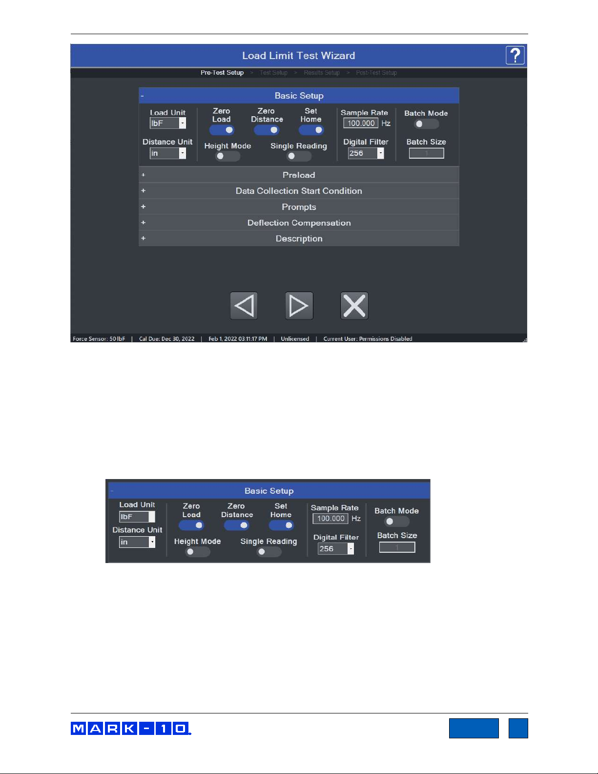
8.1.1 Pre-Test Setup
Basic Setup Panel
Load Unit
Select the desired unit of measurement. Note that not all units are supported by all force sensors
cells. Refer to the sensor’s specifications for a list of supported units.
Distance Unit
Select the desired unit of measurement.
Zero Load
Zero the load value at the start of the run.
Zero Distance
Zero the position value at the start of the run.
Find Quality Products Online at: sales@GlobalTestSupply.com
www.GlobalTestSupply.com
Page 33

Series F Test Frames + IntelliMESUR® Software User’s Guide
33
TOC
Set Home
Establish the starting position of the crosshead as the Home position. You can auto-return to this
position; this may be set in subsequent sections of the wizard.
Height Mode
To measure distance relative to a reference point established via the Height / Length Offset
function in Manual Control, enable Height Mode. Height measurements are commonly used in
spring testing.
Single Reading
Only a single result and graph data point are displayed, useful when running a batch of tests
requiring only one result, such as a maximum load. Select the desired result in Results Setup.
Sample Rate
By default, IntelliMESUR records continuous data points for each run. Set the desired rate, up to
1,000 Hz (data points per second). IntelliMESUR can capture up to 1 million data points per run,
up to 10 runs, for a total of 10 million data points.
Digital Filter
Smooths out load readings in situations where there is mechanical interference in the work area
or test sample, as explained in the Preferences section.
Batch Mode
To set up a batch of multiple runs, enable this mode, then specify the number of runs.
Preload Panel
The preload function zeroes the load and/or position values upon contact with the sample,
defined as a user-specified force. The speed of the preload phase of the test may also be set
independently of the main test speed, which is configured in the subsequent step, Load Limit
Setup.
If preload is desired, enable the appropriate functions and specify the desired preload force and
speed.
Data Collection Panel
Configure the trigger at which data collection will start. Select from an elapsed time (relative to the
start of crosshead motion), load, or distance. The default graph x-axis may be also be configured,
although this can be changed at time of test in the Graph screen.
Find Quality Products Online at: sales@GlobalTestSupply.com
www.GlobalTestSupply.com
Page 34

Series F Test Frames + IntelliMESUR® Software User’s Guide
34
TOC
Tell Prompt
Ask Prompt
Prompts Panel
IntelliMESUR can prompt a message or ask a question requiring a response. Up to three
consecutive prompts may be configured.
Select the Edit icon to configure the prompt. The screen appears as follows:
Select Tell to provide information to the user, or Ask to ask a question requiring a response, such
as a serial number or lot number. The response to an Ask prompt can be saved in the Results
table of a test.
Optionally include an image to be displayed with the prompt. Select Open or the empty image
frame, then browse to the desired location. To remove an image, select Delete.
The prompt can be displayed when the test is opened, at the start of a new batch, or at the start
of each run. Make the desired selection.
Example prompts, as they appear during a test:
For convenience in high-volume testing applications, a USB barcode scanner can be used to
input a response (not available from Mark-10).
Find Quality Products Online at: sales@GlobalTestSupply.com
www.GlobalTestSupply.com
Page 35

Series F Test Frames + IntelliMESUR® Software User’s Guide
35
TOC
Deflection Compensation
Force sensors and test frames deflect under load, affecting the accuracy of distance
measurements. Series F test frames and force sensors are compensated at the factory.
To account for deflection within grips or fixtures associated with the test, IntelliMESUR provides a
utility for additional compensation. For instructions on running this utility, refer to the Deflection
Compensation section. When this process has been completed and the file has been saved,
browse to the desired file in this panel.
Description
Optionally type a test description, which can be useful in identifying tests at a later date. Example:
When opening a test, the description appears to the right of the file listing, as follows:
Find Quality Products Online at: sales@GlobalTestSupply.com
www.GlobalTestSupply.com
Page 36

Series F Test Frames + IntelliMESUR® Software User’s Guide
36
TOC
8.1.2 Load Limit Setup
Basic Setup Panel
The screen appears as follows:
Specify the target load and direction, then specify the test speed. To collect continuous data
points for each run, enable Display Results. Results may still be saved even if Display Results
is disabled.
Pass / Fail Limits
Pass and fail limits may be specified to differentiate an acceptable sample versus a reject. Enable
if desired, then specify upper and lower limits. The types of limits in this panel correspond to the
type of test. For Load Limit and Load Hold tests, the pass/fail limits are distance values. For
Distance Limit and Break Limit tests, the pass/fail conditions are load values.
When enabled, a Pass/Fail indicator appears in the upper right corner of the Graph and Results
screens. In addition, a color-coded Pass/Fail column is added to the Results table.
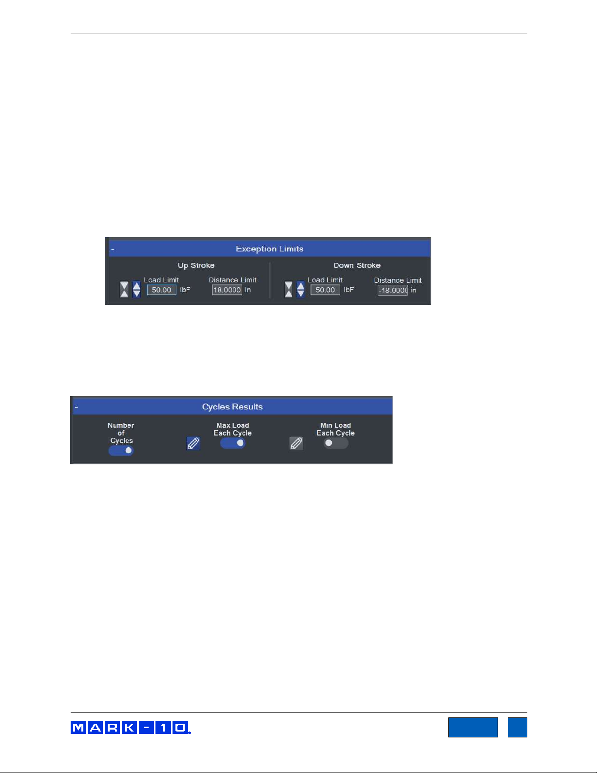
Exception Limits
If a test does not reach its target, a number of exception limits may be specified to abort the test.
Enable if desired, then specify exception limits. An exception is triggered at whichever trigger
occurs first. If an exception is triggered, the crosshead stops, and the Pass/Fail status becomes
“Exception”. Values obtained in an exception run are not included in results calculations.
Exception options:
Limit Switch
Refers to the physical upper and lower (or right and left) limit switches, positionable along the
length of the test frame column.
Distance Limit
A specified distance has been reached.
Break Threshold and Break % Drop
A specified drop in load has occurred, for example when a sample breaks or a sample slips out
Find Quality Products Online at: sales@GlobalTestSupply.com
www.GlobalTestSupply.com
Page 37

Series F Test Frames + IntelliMESUR® Software User’s Guide
37
TOC
from a grip. Specify a drop in load from the maximum value (Break % Drop). IntelliMESUR starts
monitoring for a break after the Break Threshold has been reached.
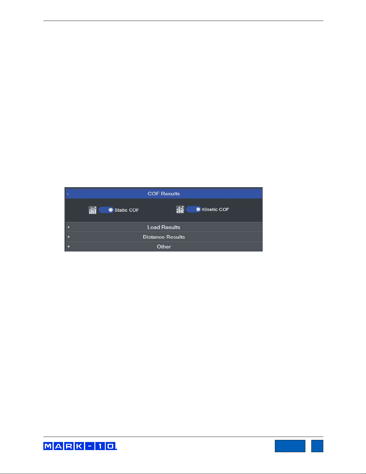
8.1.3 Results Setup
IntelliMESUR can calculate a number of results and calculate statistics for results over multiple
runs. For example, IntelliMESUR can calculate the mean of Max Load values over a 5-run batch.
The Results appear as follows:
Load Results
Enable the desired results, then select Statistics to specify Statistics.
The screen appears as follows:
Make the desired selections, then continue.
Find Quality Products Online at: sales@GlobalTestSupply.com
www.GlobalTestSupply.com
Page 38

Series F Test Frames + IntelliMESUR® Software User’s Guide
38
TOC
Distance Results
Load Averaging
Load Averaging dynamically captures data points and averages the result over a distance or
period of time. This requirement is common in peel testing and coefficient of friction testing
applications.
Enable the result, and any required statistics, then configure the following settings:
Trigger Force
The minimum force required to start the averaging sequence. Select compression or
tension. To start averaging immediately, set this value to zero.
Post-Trigger Delay
An initial delay may be configured, for example to omit the initial force spike at the
beginning of a peel test. To start averaging immediately after the trigger force, set this
value to zero.
Stop Condition
Stop averaging when the specified distance is reached or time period elapses.
The following graph is a representative example of a time-based averaging test with post-trigger
delay:
Find Quality Products Online at: sales@GlobalTestSupply.com
www.GlobalTestSupply.com
Page 39

Series F Test Frames + IntelliMESUR® Software User’s Guide
39
TOC
Other
Optionally include the date and time of the test, along with corresponding crosshead speed.
8.1.4 Post-Test Setup
In this step, a number of post-test preferences and settings can be configured.
Basic Setup
Return Home
Crosshead returns to the prevously set Home position at the end of the test.
Save Data
Automatically save all raw, continuous data for each run.
Save Results
Automatically save results for the test. Results are visible in the Results screen.
Default View
When opening a test, default to the Graph view or Results view. Regardless of the default, you
can switch between views after the test has completed.
Export Settings
®
IntelliMESUR
both. Files are exported as .csv using the same formatting described in the manual export
function in the Running a Test section.
Find Quality Products Online at: sales@GlobalTestSupply.com
can automatically export data from a single run or results from a batch of runs, or
www.GlobalTestSupply.com
Page 40

Series F Test Frames + IntelliMESUR® Software User’s Guide
40
TOC
Export Run Data
Enable if desired, then select an export preference:
Create New File
Creates a new file automatically. The file name includes the test name and time stamp,
for example: Peel Test-Dec-7-2020-03-25-57-PM
Specify the destination folder by browsing to the appropriate location.
Overwrite File
Overwrites an existing file. This function is useful for third-party applications which read
periodically from the same file, such as SPC software. Specify the file name as desired.
Specify the file name and browse to an appropriate destination folder.
Export Results
Enable if desired, and follow the same instructions as above.
Graph Setup
Auto-Scale
Auto-Scale automatically increases the X- and Y-axis maximum values as the test proceeds,
ensuring that the graph curve is zoomed in as much as possible while fitting the entire curve.
Maximum & Minimum
To specify fixed maximum and minimum axis values instead of automatical scaling, enter the
desired values.
Invert
IntelliMESUR processes force, distance, and time data as follows:
Tension forces are plotted as negative values.
Compression forces are plotted as positive values.
Upward or rightward motion is displayed as increasing distance values, while downward
or leftward motion is displayed as decrementing values. If the movement continues past a
distance of 0, a positive values becomes negative, and vise versa, as illustrated below:
Find Quality Products Online at: sales@GlobalTestSupply.com
www.GlobalTestSupply.com
Page 41

Series F Test Frames + IntelliMESUR® Software User’s Guide
41
TOC
The most common method to plot a curve is to plot up and to the right. To achieve this trajectory,
or other type of trajectory, data for each axis may be inverted to compensate for the plotting
protocol mentioned above.
Example:
To plot a tension test up and to the right, invert the Y-axis (load), while leaving the X-axis uninverted. Had the Y-axis not been inverted, increasing tension force would be displayed by a
downward dipping plot, as illustrated below:
Default X-Axis
Set the default x-axis to distance or time. Note that following any test, you can toggle between
distance or time via dedicated buttons in the Graph screen.
Overlay Runs on Graph
Up to 10 most recent runs may be plotted on the graph simultaneously. For more information,
refer to the Graph screen section.
Folders
Browse to the desired folder locations for test configuration files, data, results, and reports.
Find Quality Products Online at: sales@GlobalTestSupply.com
www.GlobalTestSupply.com
Page 42

Series F Test Frames + IntelliMESUR® Software User’s Guide
42
TOC
Select Next to complete the test setup. When prompted, select Save & Run, Save & Go Home,
or Cancel. If saving the test, the screen appears as follows:
8.2 Distance Limit
A Distance Limit test shares most attributes with a Load Limit test, with the exception of the Basic
Setup panel of the Test Setup step. The panel appears as follows:
The unique settings are as follows:
Test Direction
Select upward or downward motion for vertical test frames, or rightward and leftward for model
F505H.
Target Distance
Crosshead will stop at the specified distance.
Find Quality Products Online at: sales@GlobalTestSupply.com
www.GlobalTestSupply.com
Page 43

Series F Test Frames + IntelliMESUR® Software User’s Guide
43
TOC
8.3 Break Limit
Break Limit tests are useful for a wide variety of destructive applications, including peel testing, wire
crimp pull-off testing, tensile testing, and many others. The crosshead will stop once IntelliMESUR has
detected that the sample has broken.
Setting up a Break Limit test is similar to Load Limit and Distance Limit tests, with the exception of the
Basic Setup panel of the Test Setup step. The panel appears as follows:
IntelliMESUR starts monitoring for a break when the Break Threshold has been reached. This value
should be set lower than the anticipated breaking load. IntelliMESUR identifies a break when the load has
dropped by the specified percentage from the maximum load.
Example: If Break % Drop is set to 40% and the maximum load is 100 lbF, the crosshead will stop when
the load drops to 60 lbF.
8.4 Load Hold
With IntelliMESUR’s load holding function, the crosshead stops at a specified load, then dynamically
adjusts its position to maintain that load over a specified period of time.
Setting up a Load Hold test is similar to Load Limit and Distance Limit tests, with the exception of the
Basic Setup panel of the Test Setup step. The panel appears as follows:
Set a target load, hold duration in hours, minutes, and seconds, then the approach speed.
8.5 Cycle Test
IntelliMESUR’s Cycle Test is designed for repetitive applications such as fatigue and durability.
Setting up a Cycle Test is mostly similar to Load Limit and Distance Limit tests. Note the following
unique features:
Find Quality Products Online at: sales@GlobalTestSupply.com
www.GlobalTestSupply.com
Page 44

Series F Test Frames + IntelliMESUR® Software User’s Guide
44
TOC
8.5.1 Cycle Test Setup
Basic Settings
Cycle Type
Select number of cycles, or specify a period of time, in hours, minutes, and seconds.
Up Stroke / Down Stroke Settings
Up Stroke (crosshead moving up or right) and Down Stroke (crosshead moving down or left)
settings may be set independently of each other. The crosshead will stop at one of the following
three targets:
Find Quality Products Online at: sales@GlobalTestSupply.com
www.GlobalTestSupply.com
Page 45
Series F Test Frames + IntelliMESUR® Software User’s Guide
45
TOC
Load
Select tension or compression, then specify the load.
Distance
Specify as desired.
Limit Switch
Crosshead stops when it reaches the upper physical limit switch.
Speed
Specify the crosshead speed.
Dwell Time
Specify how much time the crosshead waits at the target before reversing.
Exception Limits
Specify exception limits for each stroke independently.
8.5.2 Results Setup
Results setup is the same as in other tests, with the addition of the Cycles Results panel. The following
additional results may be displayed in the Results table:
Number of Cycles
Maximum Load Each Cycle
Optionally add statistics for this result.
Minimum Load Each Cycle
Optionally add statistics for this result.
Find Quality Products Online at: sales@GlobalTestSupply.com
www.GlobalTestSupply.com
Page 46

Series F Test Frames + IntelliMESUR® Software User’s Guide
46
TOC
8.6 COF Test
Note: The COF Test module is optional. See Optional Functions under Settings for activation
instructions.
In a typical coefficient of friction test, a sled wrapped with sample material is dragged along another piece
of material clamped onto a base fixture. Below is an example configuration for paper testing:
A COF Test shares most attributes with a Distance Limit test, with the exception of the Basic Setup
panel of the Test Setup step. The panel appears as follows:
Find Quality Products Online at: sales@GlobalTestSupply.com
www.GlobalTestSupply.com
Page 47
Series F Test Frames + IntelliMESUR® Software User’s Guide
47
TOC
The settings are as follows:
Sled Weight
The weight of the sled.
Trigger Load
The load threshold at which IntelliMESUR starts to collect data.
Post-Trigger Delay
Specify a time delay after the Trigger Load before collecting data.
Test Distance
Specify as desired. Data collected between the Trigger Load and Test Distance are used to
calculate the static and dynamic coefficients of friction.
Speed
Specify the crosshead speed.
Display Result
Include results. The Results step adds the following COF results:
Static COF Maximum force divided by the sled weight.
Kinetic COF Average force divided by the sled weight.
Find Quality Products Online at: sales@GlobalTestSupply.com
www.GlobalTestSupply.com
Page 48

Series F Test Frames + IntelliMESUR® Software User’s Guide
48
TOC
9 CREATING A MULTI-STEP TEST
A Multi-Step test can string together any number of basic test functions, data collection steps, data zero
steps, cycling, and prompts. Steps may be placed in the desired order, then re-ordered as desired.
9.1 Multi-Step Overview
The initial screen appears as follows:
Available steps are listed in the left side of the screen, and may be inserted into the step sequence to the
right.
Find Quality Products Online at: sales@GlobalTestSupply.com
www.GlobalTestSupply.com
Page 49

Series F Test Frames + IntelliMESUR® Software User’s Guide
49
TOC
To insert a step, highlight an existing step. It will become blue. Then click the desired step. It will be
inserted after the currently selected step. An example test is below:
The step sequence must contain the three steps listed above: Pre-Test, Results, and Post-Test. To edit
these steps, select Edit, and configure the parameters the same way as in Basic Test setup.
To move a step forward or back, use the Up and Down buttons. Select the Delete button to remove the
step.
The selection of results is expanded as compared to Basic Test setup, as follows:
Load Results:
Find Quality Products Online at: sales@GlobalTestSupply.com
www.GlobalTestSupply.com
Page 50

Series F Test Frames + IntelliMESUR® Software User’s Guide
50
TOC
Distance Results:
9.2 Step Types
Multi-step tests build upon the same functions as in Basic Tests, while separating out datum, prompting,
zero, and go-home functions. Preload is not integrated into steps as in Basic Tests. Instead, a preload
must be manually configured as a separate Load Limit step, followed by a Zero step.
Available steps are as follows:
9.2.1 Load, Distance, and Break
Each of these steps may be set up in the same manner described in Basic Test setup.
9.2.2 Hold
Hold a load (as described in Basic Test setup) or hold a position. Specify the hold period in hours,
minutes, and seconds.
To include the data points received during the Hold step in the Results calculations, enable Display
Results.
Find Quality Products Online at: sales@GlobalTestSupply.com
www.GlobalTestSupply.com
Page 51

Series F Test Frames + IntelliMESUR® Software User’s Guide
51
TOC
9.2.3 Loop
The Loop function repeats a range of steps. Insert this step after the last step to be repeated.
Select either a number of loops or a time duration for constant looping. Then, enter the Starting Step
number. Enter Number of Loops or Duration.
9.2.4 Datum
A datum establishes a local offset of load and/or distance. When the datum step is reached, the load
and/or distance will change by the values set in the Load and Distance fields. Enable one or both of
these fields.
Note that datums do not change the system offset established in the Height / Length Offset utility, but
rather, only offsets the data collected during the test.
To include the data points received during the Hold step in the Results calculations, enable Display
Results.
Up to two datums may be used per test.
9.2.5 Prompt
Setting up a prompt in a multistep test is the same as described in the Basic Test Setup section.
Find Quality Products Online at: sales@GlobalTestSupply.com
www.GlobalTestSupply.com
Page 52
Series F Test Frames + IntelliMESUR® Software User’s Guide
52
TOC
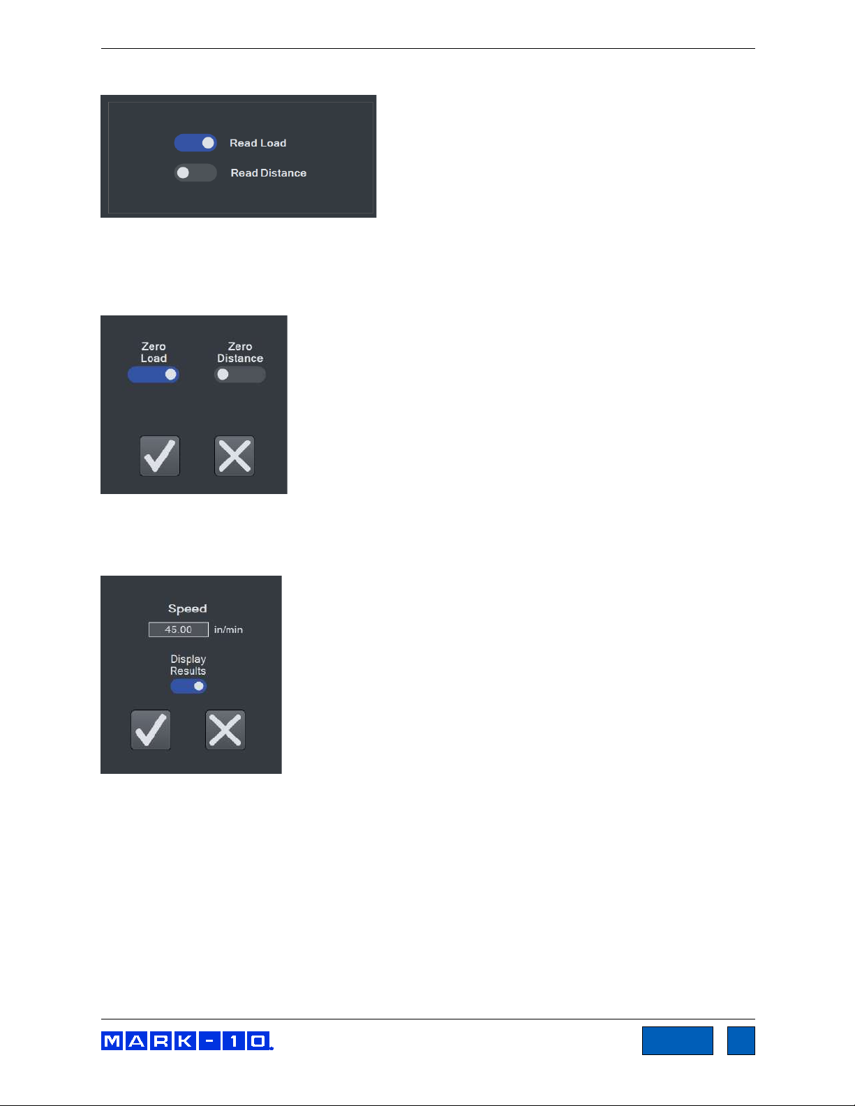
9.2.6 Data
A Data step saves the current load and/or distance value in the Results table. Make the desired
selections.
9.2.7 Zero
A Zero step zeroes the load and/or distance. Make the desired selections.
9.2.8 Home
A Home step returns the crosshead to the Home position at the specified speed.
To include the data points received during the Home step in the Results calculations, enable Display
Results.
Find Quality Products Online at: sales@GlobalTestSupply.com
www.GlobalTestSupply.com
Page 53

Series F Test Frames + IntelliMESUR® Software User’s Guide
53
TOC
10 RUNNING A TEST
10.1 Favorite Tests
Saved tests may be designated as favorites, for quick access when selecting Open Test from the Home
screen. The screen appears as follows:
10.1.1 Creating a Favorite
Select Assign Favorite, then select the desired box location. The screen appears as follows:
Find Quality Products Online at: sales@GlobalTestSupply.com
www.GlobalTestSupply.com
Page 54

Series F Test Frames + IntelliMESUR® Software User’s Guide
54
TOC
Browse to the desired file, then select Open. Optionally associate an image with the favorite box by
making the appropriate selection to the next screen:
If selecting Yes, browse to the desired image, then select Open. The screen appears as follows:
Find Quality Products Online at: sales@GlobalTestSupply.com
www.GlobalTestSupply.com
Page 55

Series F Test Frames + IntelliMESUR® Software User’s Guide
55
TOC
10.1.2 Unassigning a Favorite
Select Unassign Favorite, then select the desired test.
10.1.3 Edit a Test
Select Edit Test, then select the desired test.
10.1.4 Opening a Test
Select a previously assigned favorite, or select Other Test to browse for other tests not assigned as
favorites.
Depending on the test setup, the initial view is either Graph or Results.
Find Quality Products Online at: sales@GlobalTestSupply.com
www.GlobalTestSupply.com
Page 56

Series F Test Frames + IntelliMESUR® Software User’s Guide
56
TOC
10.2 Graph View
The screen appears as follows:
Multiple runs may be viewed on the graph at the same time. If Overlay Runs on Graph is selected in the
test setup, the screen appears as follows:
Select the desired runs to view.
Find Quality Products Online at: sales@GlobalTestSupply.com
www.GlobalTestSupply.com
Page 57

Series F Test Frames + IntelliMESUR® Software User’s Guide
57
TOC
10.2.1 Basic Information
Along the top of the screen, the following information is always displayed:
Batch counter – if Batch is enabled in the test setup, the current run number and batch size are
displayed. Ex. “Batch: 2/3” = 2 runs completed out of a batch of 3.
Load – current load.
Distance – current distance.
Status – crosshead motion status, such as Moving Up, Moving Down, Stopped, Home,
Emergency Stop, etc.
Pass / Fail Indicator – if Pass / Fail Limits are enabled in the test setup, a Pass, Fail, or
Exception indicator will be displayed at the end of each run. If an exception occurs, the type of
exception will be shown in the Status window and in the Results table.
For multi-step tests, a pass / fail indicator can be configured for each step, and is represented in
the Results table (refer to the Results View section for more information). If any step within a
multi-step test has failed, IntelliMESUR considers that the entire run has failed, and displays Fail
in the main indicator described above.
10.2.2 Graph Controls
The following controls are provided below the graph:
Line Width
Select the button, then choose the desired plot thickness:
Invert X-Axis, Invert Y-Axis
Invert the plots, as desired. Further explanation is provided in the Graph Setup sub-section of
Creating a Basic Test. Note that inverting axes in this screen will not be saved to the test setup.
Edit the test to save default axis settings.
Distance / Time selector
Select Distance or Time as the x-axis. The y-axis is always Load.
Cursor
Use the cursor to identify the x- and y-values along any point of a plot. Click or touch any point
along a plot to see the values. Example below:
Find Quality Products Online at: sales@GlobalTestSupply.com
www.GlobalTestSupply.com
Page 58

Series F Test Frames + IntelliMESUR® Software User’s Guide
58
TOC
The cursor will snap to the closest plot when multiple runs are displayed simultaneously.
Zoom
To zoom by hand, pinch fingers to zoom in and out. To zoom in via mouse, click and drag to
create a zoom window.
To zoom out, select Graph Reset.
Graph Reset
Zooms out to show the complete plot.
10.2.3 Starting The Test
To start the test, select Start. To interrupt a test while it is running, select Stop.
10.3 Results View
10.3.1 Basic and Multi-step Test Result Tables
The screen appears as follows for a basic test:
Results and statistics are presented as configured in the test setup. The Statistics table below the
Results table is aligned to the results, as depicted below:
Find Quality Products Online at: sales@GlobalTestSupply.com
www.GlobalTestSupply.com
Page 59

Series F Test Frames + IntelliMESUR® Software User’s Guide
59
TOC
Below is an example of a one-loop, two-cycle multi-step test:
The following additional information is displayed in a multi-step test versus a basic test:
Run No.
Run number.
Step No.
Indicates the step number within the multi-step sequence. Only steps configured to display results
are shown in this table.
If more than one loop is configured in the test, the table includes the Loop No. and Cycle Count
columns, as shown below:
Find Quality Products Online at: sales@GlobalTestSupply.com
www.GlobalTestSupply.com
Page 60

Series F Test Frames + IntelliMESUR® Software User’s Guide
60
TOC
Since any number of loops may be configured in a multi-step test, Loop No. identifies the loop
within the test. Cycle Count refers to the cycle number within a specific Loop step.
Overall Run Status
When there is more than one pass/fail status per run, an additional row is added to the Results
table, labeled Overall Run. This provides a comprehensive pass/fail determination for the entire
run. If all steps pass, the Overall Run status is Pass. If any step fails, the overall status is Fail.
Basic information and test start and stop functions are the same as in the Graph screen.
10.3.2 Results Presentation
If the run fails, the entire row will appear red, and the Status cell includes a description of the failure.
Example:
An exception is denoted in the same manner, highlighted orange. Example:
When an exception occurs, the crosshead stops. It will not return to the Home position, even if Return
Home is enabled in the test setup. To manually return home, select Return Home.
10.3.3 Invalidating a Result
There may be an occasion where the result must be invalidated, for example, if the test was started
accidentally, or the sample slipped out of the grip. In such instances, a run may be invalidated.
Highlight anywhere within the row, then select Invalidate Run. A message box appears as follows:
Select the reason from a pre-populated list, or select Other and enter a custom reason.
Find Quality Products Online at: sales@GlobalTestSupply.com
www.GlobalTestSupply.com
Page 61

Series F Test Frames + IntelliMESUR® Software User’s Guide
61
TOC
The Status cell will be highlighted yellow, as shown in the following example:
Note: once a run has been invalidated, it cannot be re-validated.
10.3.4 Results Processing
Save Results
Save results to a file, which can later be recalled. IntelliMESUR automatically assigns a file name
containing the test name, followed by a time stamp. Example: Peel test-Dec-7-2020-03-25-57-PM
The file name may be changed if desired.
Recall Results
Recall previously saved results.
Note: Any currently displayed results will be deleted when previous results are recalled. Consider
saving current results first.
Export Results
Export results to a .csv file. The file name is automatically assigned as described above. An
example results file opened in Excel appears as follows:
Clear Results
Clear all results from the table.
Note: Clearing results also clears the graph.
Find Quality Products Online at: sales@GlobalTestSupply.com
www.GlobalTestSupply.com
Page 62
Series F Test Frames + IntelliMESUR® Software User’s Guide
62
TOC
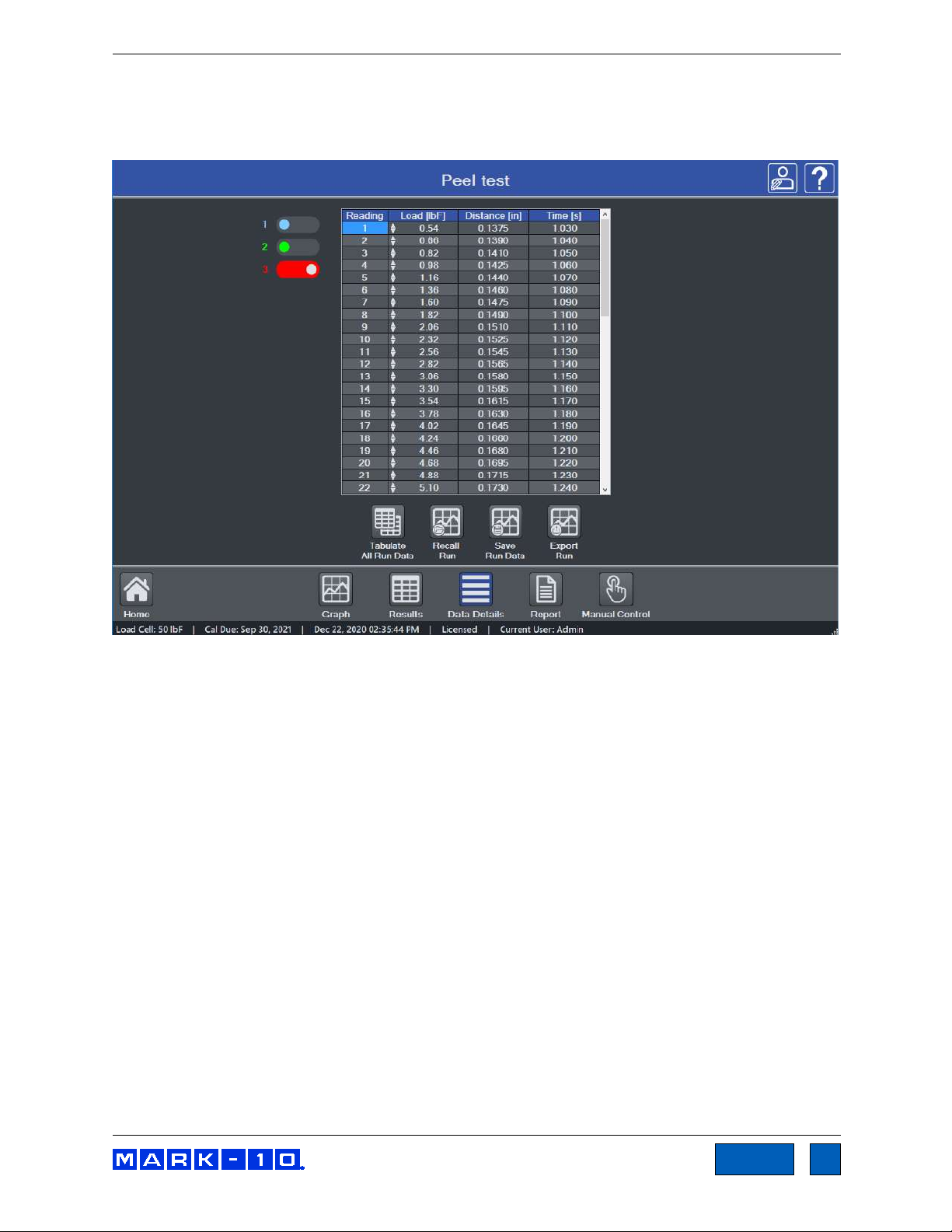
10.4 Data Details View
Data Details view tabulates raw data for a run, including reading number, load, distance, and elapsed
time. The screen appears as follows:
If Overlay Runs on Graph is selected in the test setup, data for up to 10 runs may be viewed by
selecting the desired run number to the left of the table.
10.4.1 Additional Functions
Tabulate All Run Data
The table populates up to 4,000 data points. If the run contains more than 4,000 points,
IntelliMESUR filters the data to maintain a maximum of 4,000 points. To view up to 1 million
points per run, the maximum per run, select Tabulate All Run Data. Larger data sets may
require several minutes to fully tabulate.
Recall Run
Recall data from a previously saved run.
Save Run Data
Save the run data for future recall.
Export Run
Export the run data to a .csv file. An example results file opened in Excel appears as follows:
Find Quality Products Online at: sales@GlobalTestSupply.com
www.GlobalTestSupply.com
Page 63

Series F Test Frames + IntelliMESUR® Software User’s Guide
63
TOC
10.5 Creating a Report
A report may be created, containing the results, graph, equipment used, and other pertinent information.
The screen appears as follows:
10.5.1 Creating a Template
Open a previously saved template by selecting Open Template, or create a new one. As shown in the
above image, any of the following information may be specified in a report template, as desired:
Find Quality Products Online at: sales@GlobalTestSupply.com
www.GlobalTestSupply.com
Page 64

Series F Test Frames + IntelliMESUR® Software User’s Guide
64
TOC
Company Logo
Browse for a company logo, or other image, and select the desired alignment at the top of the
report.
Test Image
If the test is saved in Favorites with an associated image, that same image is included in the
report template by default. Otherwise, browse to the desired image.
Include
System Information
IntelliMESUR software version
Test frame model number
Test frame force capacity
Test frame serial number
Test frame firmware version
Force sensor model number
Force sensor force capacity
Force sensor serial number
Force sensor previous calibration date
Force sensor next calibration date
Results
Graph
Company Info
Use this space to enter your company’s contact information, or any other pertinent information.
This will appear directly below the logo.
Report Title
Initial Text, Additional Text, Conclusion Text
After filling in the above information, optionally save the template by selecting Save Template.
Otherwise, select Print Preview to preview the report or Print to create it.
An example report is as follows:
Find Quality Products Online at: sales@GlobalTestSupply.com
www.GlobalTestSupply.com
Page 65

Series F Test Frames + IntelliMESUR® Software User’s Guide
65
TOC
Find Quality Products Online at: sales@GlobalTestSupply.com
www.GlobalTestSupply.com
Page 66

Series F Test Frames + IntelliMESUR® Software User’s Guide
66
TOC
10.6 Recalling Previous Data
To recall previously saved data, select Recall Test Data from the Home screen.
Then select Recall Run or Recall Results, as appropriate, and select the desired file.
11 CALIBRATION
11.1 Force Sensor Calibration
Mark-10 recommends calibrating force sensors at least once per year. Series FS05 and R07 force
sensors may be calibrated while installed on a Series F test frame, or may be removed the frame and
calibrated with a Mark-10 Model M5I or Model M7I indicator.
11.1.1 Calibrating on a Series F Frame
1. Using Manual Control, move the crosshead high enough to accommodate calibration fixtures
and equipment.
A master load cell should be mounted to the test frame and interface with the force sensor, along
with appropriate mounting brackets and fixtures. Compression and tension springs are
recommended. Caution should be taken while handling such equipment.
2. Select Calibration from the Settings screen. The screen appears as follows:
The Previous Calibration Date and Previous Calibration Due Date are displayed at the top.
To update the calibration date to today’s date, select Update Calibration Date to Today, then
set the Next Calibration Due Date as desired. The calibration date may be updated regardless
Find Quality Products Online at: sales@GlobalTestSupply.com
www.GlobalTestSupply.com
Page 67

Series F Test Frames + IntelliMESUR® Software User’s Guide
67
TOC
of whether calibration takes place. This accounts for situations in which the force sensor accuracy
has been verified to within specification and re-calibration is not necessary. Note that the due
date may be modified regardless of whether the calibration date was updated.
Optionally configure a Calibration Reminder, in days.
To save the settings and return to the Home screen without calibrating, select Save and Exit. To
continue with calibration, select Save and Calibrate.
3. After selecting Save and Calibrate, the first screen of the calibration wizard appears as follows:
The calibration date is intended for informational purposes only. Because it may be
modified independently of the actual calibration, it should not be relied upon as
evidence of successful calibration.
Calibration instruction Crosshead motion control
Optionally use Demo Mode to become familiar with the steps required for calibration, without
having to physically perform any actions.
Crosshead motion controls are similar to those in Manual Control. They are available through
all calibration steps to apply the required force. FollowMe mode may not be used in steps
requiring the application of load; it can only be used in crosshead positioning steps.
Find Quality Products Online at: sales@GlobalTestSupply.com
For finest control, and to help prevent an overload, Momentary mode is
recommended. Start with a slow rate of speed.
www.GlobalTestSupply.com
Page 68

Series F Test Frames + IntelliMESUR® Software User’s Guide
68
TOC
4. The force sensor can be calibrated at up to 10 points in each direction. Enter the number of
calibration points for each direction (tension and compression). At minimum, the sensor must be
calibrated at full scale in both directions.
Note: To achieve highest possible accuracy, it is recommended to calibrate the force sensor at 5
or more even intervals in both tension and compression directions. For example, an FS05-10
force sensor (10 lbF max) should be calibrated at 2, 4, 6, 8, and 10 lbF loads in each direction.
Select Start.
5.
6. Ensure that the equipment is isolated from any vibration, then select Next.
Attach fixtures to enable compression force loading, then select Next.
7.
Optionally load and unload the force sensor to full scale several times, then select Next.
Find Quality Products Online at: sales@GlobalTestSupply.com
www.GlobalTestSupply.com
Page 69

Series F Test Frames + IntelliMESUR® Software User’s Guide
69
TOC
Zero the indicator associated with the master load cell. Engage the calibration fixtures, and
ensure that there is no load applied to the force sensor. Then select Next.
9.
Apply the indicated compression load using the crosshead motion controls. The load value
defaults to even intervals. For example, for a 50 lbF force sensor with 5 calibration points, the first
default load value is 10 lbF. All load values may be edited by up to ±20%.
Select Next. Follow the same procedure for all required loads.
10. After the final compression load, the screen appears as follows:
Configure the calibration fixtures and equipment for tension loading. Then select Next.
Find Quality Products Online at: sales@GlobalTestSupply.com
www.GlobalTestSupply.com
Page 70

Series F Test Frames + IntelliMESUR® Software User’s Guide
70
TOC
11. Subsequent steps are the same as in compression:
- Exercise the force sensor
- Install necessary fixtures
- Apply the required loads
12. When tension calibration is complete, the screen appears as follows:
Select Finish to complete the calibration, or Cancel to exit without saving the calibration.
11.1.2 Calibrating with a Mark-10 Indicator
Series FS05 and R07 force sensors may be removed and calibrated in a different location with a Mark-10
model M5I or M7I indicator with minimum firmware version of 2.2.8.
Series R07 force sensors plug directly into an indicator via its Plug & Test
®
connector, as shown below:
Series FS05 force sensors require an adapter part no. AC1083 to plug into an indicator, as shown below:
The optional extension cable part no. AC1084 can be useful in addition to AC1083 where the indicator
cannot be positioned close to the force sensor.
For calibration instructions, refer to the indicator’s user’s guide.
Find Quality Products Online at: sales@GlobalTestSupply.com
www.GlobalTestSupply.com
Page 71

Series F Test Frames + IntelliMESUR® Software User’s Guide
71
TOC
11.2 Speed and Distance Calibration
Mark-10 recommends verification of speed and distance accuracy once per year. Note that no
adjustments may be made. Calibration is offered by Mark-10, as well as certain distributors and thirdparty laboratories.
11.3 Test Frame Deflection Compensation
Load cells within force sensors deflect under load. Test frames also deflect under load, affecting the
accuracy of distance measurements. Series F test frames, Series FS05 force sensors, and Series R07
force sensors are compensated at the factory.
However, to account for additional deflection within grips or fixtures associated with the test, IntelliMESUR
provides a utility for further compensation.
1. Install the necessary grips and fixtures. Using Manual Control, carefully move the grips or
fixtures close together until they are almost touching.
2. Select Deflection Compensation from the Settings screen. The screen appears as follows:
3. Configure the direction, tension or compression, then set the target load.
4. Create a new deflection compensation file, or overwrite a previously saved file, by browsing to the
desired file location.
5. Select Run. IntelliMESUR will indicate when the compensation is complete.
6. The saved deflection compensation file may now be associated with any test, as described in
previous sections.
Find Quality Products Online at: sales@GlobalTestSupply.com
www.GlobalTestSupply.com
Page 72

Series F Test Frames + IntelliMESUR® Software User’s Guide
72
TOC
12 MAINTENANCE & SERVICE – MODELS F105 / F305 / F505 / F505H
12.1 Physical Maintenance
Series F test frames should be operated in a dry and clean area. Under these circumstances the main
consideration is lubrication of the ball screw and slider. Periodic lubrication improves performance and
increases the longevity of test frame components.
12.1.1 Ball screw lubrication – twice per year
Ball screw lubrication frequency should increase if the frame is operated in adverse environmental
conditions, including airborne dust, temperature and humidity extremes, and other factors. Follow these
instructions:
1. Remove the upper and lower bellows to expose the ball screw, by separating the Velcro strips at
each end of the crosshead. Velcro locations are identified in the image below:
2. Using a brush, apply a small amount of general-purpose bearing grease to the screw, as shown
in the image below:
3. Cycle the crosshead up and down several times until the newly applied grease has been spread
evenly over the length of the screw.
4. Re-install the bellows.
Find Quality Products Online at: sales@GlobalTestSupply.com
www.GlobalTestSupply.com
Page 73

Series F Test Frames + IntelliMESUR® Software User’s Guide
73
TOC
12.1.2 Slider lubrication – once per year
Slider lubrication frequency should increase when used in in adverse conditions. Follow these
instructions:
Two people are recommended for this procedure, due to the risk of tipping.
1. Flip the test frame upside down, as shown below. Be sure to do this on a flat and secure working
surface.
2. While one person is supporting the column, the other person removes six screws from the
underside of the base of the test frame, as shown below:
Find Quality Products Online at: sales@GlobalTestSupply.com
www.GlobalTestSupply.com
Page 74

Series F Test Frames + IntelliMESUR® Software User’s Guide
74
TOC
3. Remove the base, then remove the two screws on the right, as shown below:
4. Remove the Mark-10 logo strip, then remove all screws from the side of the test frame, as shown
below:
5. Locate the grease receptacle on the slider, as identified below:
Find Quality Products Online at: sales@GlobalTestSupply.com
www.GlobalTestSupply.com
Page 75
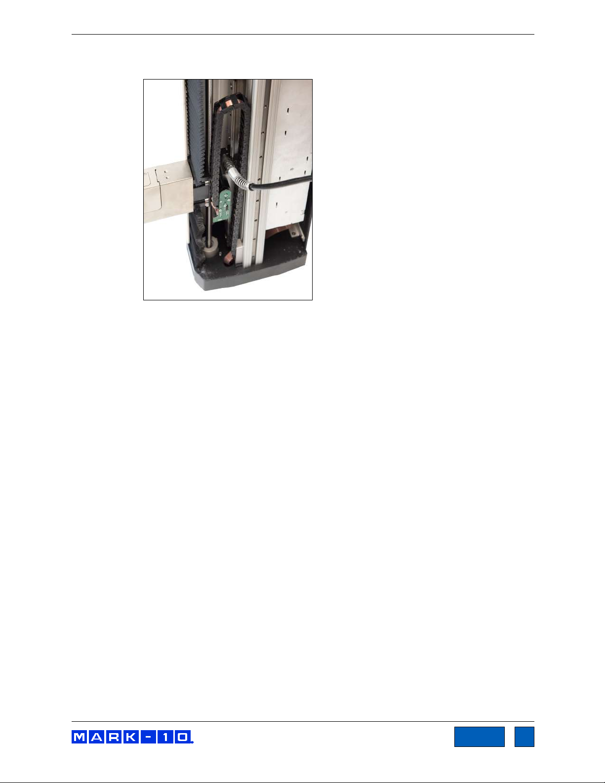
Series F Test Frames + IntelliMESUR® Software User’s Guide
75
TOC
6. Using a grease gun, add general purpose bearing grease to the inside of the slider until full. Wipe
clean any spillage. Refer to the image below:
7. Cycle the crosshead up and down several times until the newly applied grease has been spread
evenly over the length of the slide.
8. Re-assemble by repeating steps 1 through 4 in reverse.
12.1.3 Check for loosened grips and attachments – daily
Check to ensure that the grips attached to the force sensor and base plate are firmly secured. Looseness
could result in a potentially hazardous situation.
12.1.4 Check for loosened components – once per month
1. Remove the test sample from the test frame.
2. Attempt to loosen subcomponents of the test frame (ex. fasteners, brackets, etc.). All components
should be firmly attached. If any looseness is detected, stop using the test frame and contact
a distributor for instructions.
Find Quality Products Online at: sales@GlobalTestSupply.com
www.GlobalTestSupply.com
Page 76

Series F Test Frames + IntelliMESUR® Software User’s Guide
76
TOC
12.2 Removing the Motor Drive Unit (MDU)
The MDU is the self-contained location of most of the test frame’s electronics, and is designed for quick
removal and replacement in the event of service or repair. If requested by Mark-10 or a distributor to
remove and/or replace the MDU, follow these instructions:
1. Disconnect power to the test frame.
2. Remove the screws from the rear panel, then remove the panel.
3. When the MDU is accessible, disconnect the four connectors and ground wire identified in the
image below. To more easily access the ground wire, loosen one of the screws connecting the Tshaped bracket to the base, and swing it around.
4. Partially loosen the four screws securing the MDU to the frame, lift the MDU up slightly, and pull
out, as shown in the image below-right. Reinstall in the same fashion.
Locations of connectors, ground wire, and bracket Removing the MDU
Find Quality Products Online at: sales@GlobalTestSupply.com
www.GlobalTestSupply.com
Page 77

Series F Test Frames + IntelliMESUR® Software User’s Guide
77
TOC
13 MAINTENANCE & SERVICE – MODELS F1505 / F1505S / F755 / F755S
13.1 Physical Maintenance
Series F test frames should be operated in a dry and clean area. Under these circumstances the main
consideration is lubrication of the ball screw and slider. Periodic lubrication improves performance and
increases the longevity of test frame components. On average, lubrication is recommended twice per
year. However, the frequency should increase if the frame is operated in adverse environmental
conditions, including airborne dust, temperature and humidity extremes, and other factors.
13.1.1 Ball screw lubrication
Follow these instructions for proper ball screw lubrication:
1. Remove the upper and lower bellows to expose the ball screw, by separating the Velcro strips at
each end of the crosshead. Velcro locations are identified in the image below:
2. Using a brush, apply a small amount of general-purpose bearing grease to the screw, as shown
in the image below:
3. Cycle the crosshead up and down several times until the newly applied grease has been spread
evenly over the length of the screw.
4. Re-install the bellows.
Find Quality Products Online at: sales@GlobalTestSupply.com
www.GlobalTestSupply.com
Page 78

Series F Test Frames + IntelliMESUR® Software User’s Guide
78
TOC
13.1.2 Slider lubrication
As with the ball screw, periodic lubrication of the slider improves performance and increases the longevity
of test frame components. Frequency depends on environmental conditions and usage.
Follow these instructions for proper slider lubrication:
1. Lay the test frame on its side on a flat and secure working surface. Exercise caution while doing
so, as the test frame is heavy.
2. Remove the upper and lower bellows to expose the slider, as per the instructions above.
3. Locate the grease receptacle on the slider, identified in the below image:
4. Using a grease gun, add general purpose bearing grease to the inside of the slider until full. Wipe
clean any spillage. Refer to the image below:
5. Cycle the crosshead up and down several times until the newly applied grease has been spread
evenly over the length of the slide.
6. Re-install the bellows.
13.1.3 Check for loosened grips and attachments – daily
Check to ensure that the grips attached to the force sensor and base plate are firmly secured. Looseness
could result in a potentially hazardous situation.
Find Quality Products Online at: sales@GlobalTestSupply.com
www.GlobalTestSupply.com
Page 79

Series F Test Frames + IntelliMESUR® Software User’s Guide
79
TOC
13.1.4 Check for loosened components – once per month
1. Remove the test sample from the test frame.
2. Attempt to loosen subcomponents of the test frame (ex. fasteners, brackets, etc.). All components
should be firmly attached. If any looseness is detected, stop using the test frame and contact
distributor for instructions.
13.2 Removing the Motor Drive Unit (MDU)
The MDU is the self-contained location of most of the test frame’s electronics, and is designed for quick
removal and replacement in the event of service or repair. If requested by Mark-10 or a distributor to
remove and/or replace the MDU, follow these instructions:
1. Disconnect power to the test frame.
2. Remove the screws from the lower rear panel.
3. When the MDU is accessible, disconnect the four connectors and ground wire identified in the
image below.
4. Partially loosen the four screws securing the MDU to the frame, lift the MDU up slightly, and pull
out, as shown in the image below-right. Reinstall in the same fashion.
Locations of connectors and ground wire Removing the MDU
Find Quality Products Online at: sales@GlobalTestSupply.com
www.GlobalTestSupply.com
Page 80

Series F Test Frames + IntelliMESUR® Software User’s Guide
80
TOC
14 ACCESSORY INSTALLATION
14.1 Shield Installation
Optional shields can protect the operator against the dangers of airborne debris resulting from
compression and tension force testing.
14.1.1 Installing the External Emergency Switch Connector
When a shield is used, the standard emergency stop switch is located within the enclosure, preventing its
use during a test. An external limit switch is, therefore, included with Mark-10 shields.
A corresponding connector is pre-installed on Models F755, F755S, F1505, and F1505S test frames. For
Models F105, F305, and F505, the connector must be installed in the rear of the MDU. It may be factoryinstalled if ordered at time of order (reference part no. 09-1315), or installed by the customer in the field
(reference part no. 09-1315-1). Follow these instructions for field installation:
1. Remove the MDU as instructed in previous sections.
2. Punch out the opening below the label, “External Emergency Switch”, as highlighted below:
This process involves handling sensitive electronic components. We recommend
proceeding only if you have experience working with electronics. Mark-10 offers a factory
retrofit.
Find Quality Products Online at: sales@GlobalTestSupply.com
www.GlobalTestSupply.com
Page 81

Series F Test Frames + IntelliMESUR® Software User’s Guide
81
TOC
3. Remove the back panel from the MDU housing with the four screws, highlighted below:
4. Route the two wires from the rear of the connector through the hole, as shown below:
5. Connect the two cables to the white mating plug, as shown below:
Find Quality Products Online at: sales@GlobalTestSupply.com
www.GlobalTestSupply.com
Page 82

Series F Test Frames + IntelliMESUR® Software User’s Guide
82
TOC
6. Install the connector to the housing by inserting the spacer over the body of the connector, then
tightening the nut, as shown below:
7. Reassemble the MDU and reinstall, as instructed in earlier sections.
8. Connect the cable from the remote emergency stop switch.
14.1.2 Installing the Shield – Model AC1086 for Models F105 / F305 / F505
1. The shield is shipped fully assembled. Remove it from the box and remove the packaging. When
assembled to the test frame it appears as follows:
2. Position the mounting bracket on top of the test frame column, aligning the thru holes with the
corresponding threaded holes at the top of the column. Fasten the six provided socket head
screws, as shown below:
Find Quality Products Online at: sales@GlobalTestSupply.com
www.GlobalTestSupply.com
Page 83

Series F Test Frames + IntelliMESUR® Software User’s Guide
83
TOC
X
3. Plug the interlock cable into the corresponding connector in the rear of the test frame column,
labeled “Auxiliary Limits”, as shown in the Connections and Outputs section.
4. Route all cables, such as the test frame power cable and control panel cable, underneath the
shield, as shown below.
5. The door may be opened in the clockwise or counter-clockwise direction. Magnetic detents are
provided for the closed position. If the interlock cable is plugged in, IntelliMESUR’s status window
displays when the shield is open. When open, IntelliMESUR will not run, except the FollowMe
function in Manual Control, which may be used to adjust the crosshead position.
6. Plug in the cable from the shield into the connector in the rear of the MDU.
14.2 Separating the Column From The Base / Column Extension Installation – F105 / F305 / F505 / F505H
The column may be separated from the base to accommodate alternative mounting arrangements, for
considerations such as safety, increased sample clearance, integration into existing equipment, etc.
14.2.1 Removing the base from the column
Do not route cables through the cutout in the sheet metal cover. Doing so can result
in damage to the cables while the door is rotating past this area. The cutout is
provided only for hand access to the connector panel.
To remove the base, follow these instructions:
1. Power off the test frame and disconnect the power cable.
Find Quality Products Online at: sales@GlobalTestSupply.com
www.GlobalTestSupply.com
Page 84

Series F Test Frames + IntelliMESUR® Software User’s Guide
84
TOC
x6
x16
x6
2. Lay the test frame on its side and remove the six screws from the underside of the base.
Carefully remove the base from the frame. Refer to the image below:
14.2.2 Retrofitting a Mark-10 AC1094-1 / -2 / -3 single column extension (optional)
If a single column extension is ordered upfront, it is pre-installed at the factory and shipped assembled.
To retrofit in the field, follow these instructions:
1. Remove the two sheet metal covers from the column extensions by loosening the 16 screws, as
identified in the images below:
2. Using the 6 screws removed from the test frame base, reinstall the base onto the lower flange of
the column extension, as shown in the image below:
Find Quality Products Online at: sales@GlobalTestSupply.com
www.GlobalTestSupply.com
Page 85

Series F Test Frames + IntelliMESUR® Software User’s Guide
85
TOC
x6
3. Attach the top flange to the bottom of the test frame column utilizing the 6 supplied screws, as
shown in the image below:
4. Position the test frame vertically and reinstall the sheet metal covers, as shown below:
Vertical column extensions present an increased tipping hazard. It is strongly recommended
that the base be fastened to a workbench utilizing the holes on the underside of the base.
Refer to the dimensional drawing for hole locations.
Find Quality Products Online at: sales@GlobalTestSupply.com
www.GlobalTestSupply.com
Page 86

Series F Test Frames + IntelliMESUR® Software User’s Guide
86
TOC
x6
14.3 Installing a double column extension – F105 / F305 / F505
Models AC1095-1 / -2 / -3 column extensions are shipped fully assembled. To mount the test frame to the
assembly, locate the 6 thru holes, match them up to the corresponding threaded holes on the underside
of the frame, and install the screws. Refer to the image below:
Find Quality Products Online at: sales@GlobalTestSupply.com
www.GlobalTestSupply.com
Page 87

Series F Test Frames + IntelliMESUR® Software User’s Guide
87
TOC
15 UPDATING SOFTWARE AND FIRMWARE
From time to time, new IntelliMESUR software versions and new test frame firmware versions will
become available. To update, select Update Software or Update Firmware the Settings screen. The
screen appears as follows:
The file will be supplied by Mark-10 or a distributor. Save the file to the desired file location, browse to it,
then select the Update button at the bottom of the screen.
Do not exit IntelliMESUR or access another screen until the update is complete.
Find Quality Products Online at: sales@GlobalTestSupply.com
www.GlobalTestSupply.com
Page 88
Series F Test Frames + IntelliMESUR® Software User’s Guide
88
TOC
F105
F305
F505
F505H
F755
F755S
F1505
F1505S
[0.5 – 1,100 mm/min]
[0.02 - 1,525 mm/min]
[0.02 - 1,800 mm/min]
Load sampling
rate:
Data acquisition
rate:
Distance
accuracy:
repeatability:
Fuse type:
60 lb
70 lb
184 lb
149 lb
197 lb
157 lb
- Use in environments up to Pollution Degree 2
Conformance:
CE
Warranty:
3 years [see individual statement for further details]
16 SPECIFICATIONS & DIMENSIONS
16.1 Specifications
Load capacity*:
Maximum travel:
Speed range:
Load accuracy
(% of full scale):
Speed accuracy:
Distance
resolution:
Limit switch
Power: Universal input 100-240 VAC, 50/60 Hz, 300W
Weight:
Environmental
conditions:
100 lbF
[0.5 kN]
Test frame: ±0.1%
Force sensor: Series FS05: ±0.1% | Series R07: ±0.15%
- Indoor use only
- Up to 6,500 ft [2,000 m] above sea level
- Temperature range: 40 - 95°F [5 - 35°C]
- Humidity range: up to 80% relative humidity at 31°C, decreasing linearly to 50% relative humidity at
- Mains supply voltage fluctuations up to ±10 % of the nominal voltage
- Transient overvoltages up to the levels of Overvoltage Category II
300 lbF
[1.3 kN]
18.0 in
[457 mm]
0.02 – 45 in/min
±0.002 in / 0.05 mm, factory-compensated at up to full load
1.2 A, 250V, 3AG, SLO BLO 4A, 3AG, SLO BLO
[27 kg]
40°C, non-condensing
500 lbF
[2.2 kN]
±0.2% of setting, virtually no variation with load
0.0005 in / 0.01 mm
±0.001 in [0.03 mm]
[32 kg]
750 lbF
[3.4 kN]
32 in
[813 mm]
0.001 - 60 in/min
20,000 Hz
1,000 Hz
Universal input 100-240
VAC, 50/60 Hz, 120W
[83 kg]
14.2 in
[360 mm]
[68 kg]
1,500 lbF
[6.7 kN]
32 in
[813 mm]
0.001 - 70 in/min
Universal input 100-240
VAC, 50/60 Hz, 450W
[89 kg]
14.2 in
[360 mm]
[71 kg]
* Load capacity is reduced at higher speeds in the following models:
- F305: limited to 200 lbF [1 kN] above 24 in [610 mm]/min
- F505 / F505H: limited to 300 lbF [1.3 kN] above 24 in [610 mm]/min
- F755 / F755S: limited to 500 lbF [2.3 kN] above 35 in [900 mm]/min
- F1505 / F1505S: limited to 1,000 lbF [4.5 kN] above 60 in [1,525 mm]/min
Find Quality Products Online at: sales@GlobalTestSupply.com
www.GlobalTestSupply.com
Page 89

Series F Test Frames + IntelliMESUR® Software User’s Guide
89
TOC
16.2 Dimensions
16.2.1 Models F105 / F305 / F505
Find Quality Products Online at: sales@GlobalTestSupply.com
www.GlobalTestSupply.com
Page 90

Series F Test Frames + IntelliMESUR® Software User’s Guide
90
TOC
16.2.2 Model F505H
Find Quality Products Online at: sales@GlobalTestSupply.com
www.GlobalTestSupply.com
Page 91

Series F Test Frames + IntelliMESUR® Software User’s Guide
91
TOC
F755
F755S
F1505
F1505S
A
50.85
[1291.6]
33.39
[848.1]
51.35
[1304.3]
33.89
[860.9]
B
8.13 – 40.13
[206.4 – 1019.2]
8.13 – 22.33
[206.4 – 567.1]
8.13 – 40.13
[206.4 – 1019.2]
8.13 – 22.33
[206.4 – 567.1]
16.2.3 Models F755 / F755S / F1505 / F1505S
Find Quality Products Online at: sales@GlobalTestSupply.com
www.GlobalTestSupply.com
 Loading...