

Page 1

Digital Controllers Series DC
MODEL DC4010 / ESMH-DC
MODEL DC4020 / ESM-DC
MODEL DC4030 / TSFM500-DC
MODEL DC4040 / TSTM-DC
User’s Guide
Page 2

Series DC Digital Controllers
Thank you!
Thank you for purchasing a Mark-10 Series DC digital test stand contro ller,
designed for use with Mark-10 motorized test stands. Mark-10 test stands and
controllers are ruggedly built for many years of service in la boratory and
industrial environments.
This User’s Guide provides setup, safety, and operation instructions for the
digital controller. Dimensions and specifications are also provided. Instructions
for the test stand may be found in a separate user’s guide.
For additional information or answers to your questions, please do not hesitate
to contact us. Our technical support and engineering teams are eager to assist
you.
Before use, each person who is to use a Series DC digital controller and
Mark-10 test stands should be fully trained in appropriate operation and
safety procedures.
TABLE OF CONTENTS
LIST OF INCLUDED ITEMS ...................................................... 3
OVERVIEW ................................................................................. 3
MECHANICAL SETUP AND SAFETY ....................................... 4
CONTROLS LAYOUT ................................................................ 7
TEST PARAMETER SETUP ...................................................... 8
OPERATING MODES ............................................................... 20
COMMUNICATING WITH MESURGAUGE ............................. 27
SPECIFICATIONS .................................................................... 29
DIMENSIONS ........................................................................... 29
WARRANTY ............................................................................. 29
OTHER MARK-10 PRODUCTS ............................................... 31
Page 3
User’s Guide
3
1 LIST OF INCLUDED ITEMS
2 OVERVIEW
There are several models within this series of digital controllers to
accommodate different test stands, as follows:
Series DC controllers have two functional modes:
1. OPERATING MODE
This is the operating mode in which testing sequences can be started and
stopped.
2. TEST PARAMETER SETUP
In this mode, test parameters are configured, such as rate of speed, number of
cycles, password editing, and other parameters.
Qty. Item
1 Series DC digital controller
1 Power cord
1 Cable, controller to test frame
1 09-1143 multi-function cable (optional)
1 09-1056 serial cable (optional)
Model For use with
DC4010 ESMH
DC4020 ESM
DC4030 TSFM500 / TSFM500H
DC4040 TSTM / TSTMH
Page 4
Series DC Digital Controllers
4
3 MECHANICAL SETUP & SAFETY
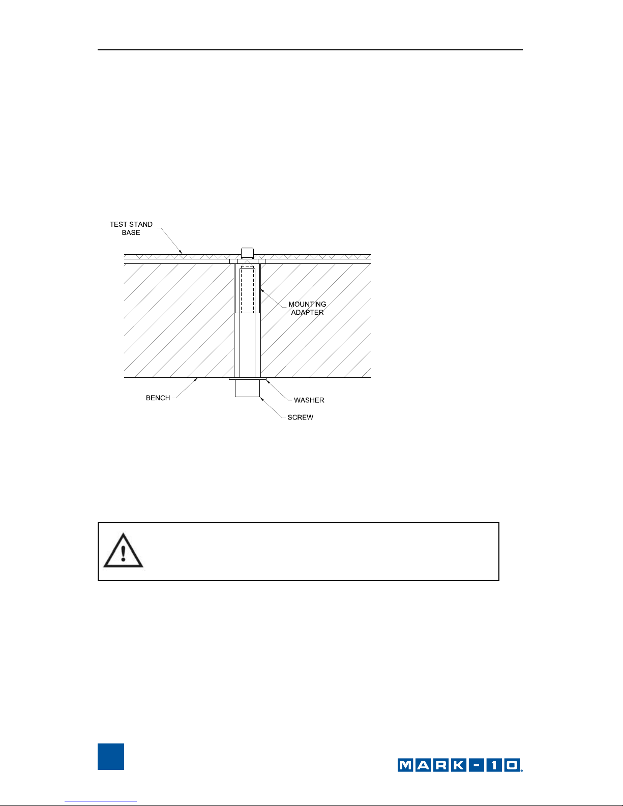
3.1 Mounting
The controller should be placed on a clean, flat and level work area free from
vibration. If desired, the controller can be secured to the work area with 1/4-20
screws fastened into the underside of the housing. The controller can also be
mounted using the ESM301-003 mounting kit. Screws of various lengths are
supplied with this kit to accommodate a range of bench thicknesses. Refer to
the following illustration for proper assembly:
In general, the controller can be mounted at any angle, although extra care
should be taken during installation and oper ation.
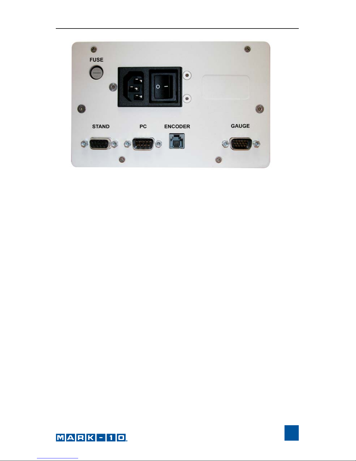
3.2 Setting Up The Controller
The power plug and controller cable must be connected to the rear of the
controller, as shown in the illustration below:
IMPORTANT: Do not fasten any screws more tha n 0.25
in [6 mm] into the base of the test stand, or damage to
internal components can occur.
Page 5
User’s Guide
5
1. Fuse
2. STAND / Controller Cable Connector
Plug one end of the cable into this connector, and the other end into the
connector adjacent to the motor on the test stand. If this cable is not
connected, the error message ENCODER ERROR will be shown on the
display and the test stand cannot be operated.
3. PC / PC Control Connector
Plug one end of the 09-1056 serial cable into this connector, and the other
end into a serial connector on a computer.
4. Power Plug Receptacle
Plug the power cord in here.
5. ENCODER / Travel Indication Connector
Applicable for TSTM / TSTMH test stands only
Plug one end of the RJ11 cable into this connector, and the other end into
the connector on the underside of the mechanism housing on the test stand.
6. GAUGE / Gauge Cable Connector
Plug one end of the 09-1143 cable into this connector, and the other end
into a Series 5, Series BG or BGI gauge.
Page 6

Series DC Digital Controllers
6
3.3 Connecting Power
Plug one end of the power cord into its receptacle at the rear of the controller
and the other end into a wall outlet with local earth ground (3-prong connector).
Before turning on power, the following safety checks and procedures should be
performed:
1. Never operate the controller if there is any visible damage to the power
cord or the test stand. The controller is powered by 110V/220V. Any
contact with this high voltage can cause serious injury or even death.
2. Ensure that the controller is kept away from water or any other
electrically conductive liquids at all times.
3. Make sure the electric al outlet powering the controller has local earth
ground (3-prong connector).
4. The controller should be serviced by a trained technician only. Power
must be disconnected before the controller is opened.
After the above safety checks and procedures have been performed, the
controller may be powered on and is ready for operation.
Page 7
User’s Guide
7
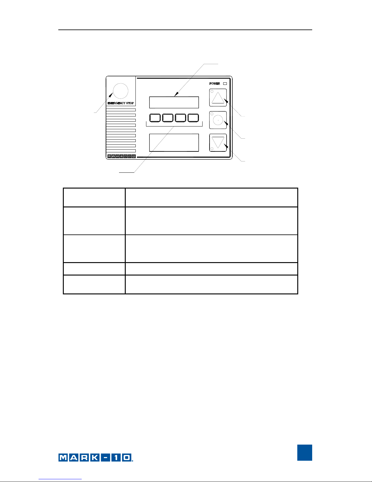
4 CONTROLS LAYOUT
* Although the direction of movement differs between test stands, this user’s
guide will refer to the buttons as UP and DOWN.
EMERGENCY
STOP
SOFT KEYS
UP
STOP /
ZERO TRAVEL DISPLAY
DOWN
DISPLAY
SOFT KEYS
Functions are determined by the
corresponding text on the display.
UP /
RIGHT / CW*
Initiates movement in the up, right, or
clockwise direction, depending on the test
stand.
DOWN /
LEFT / CCW*
Initiates movement in the down, left, or
counterclockwise direction, depending on the
test stand.
STOP
Stops movement.
EMERGENCY
STOP
Stops movement and disables the test stand
until reset.
Page 8
Series DC Digital Controllers
8
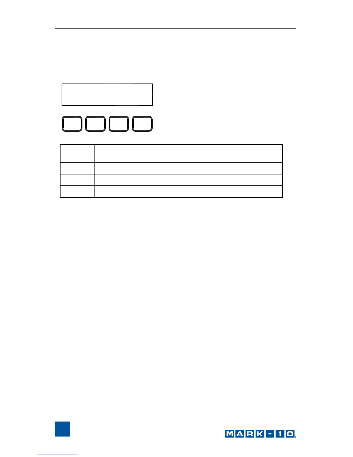
5 TEST PARAMETER SETUP
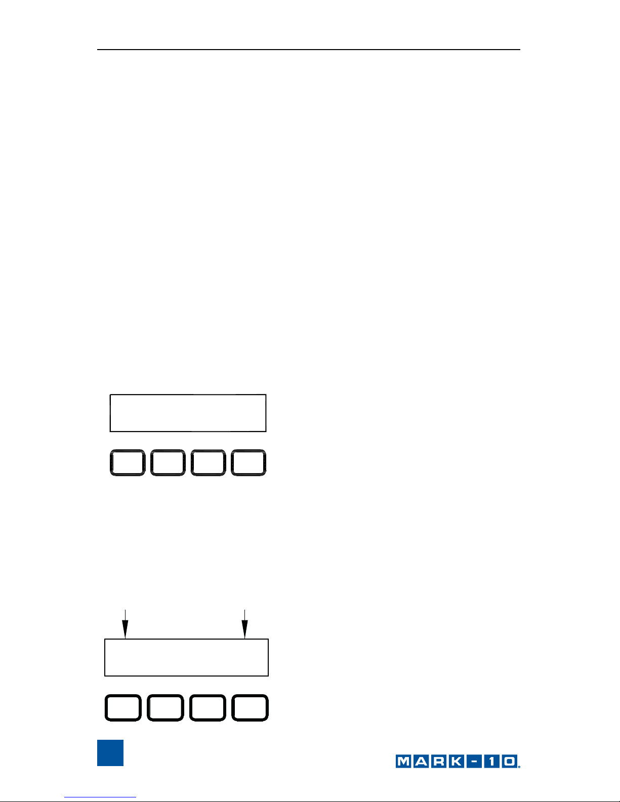
This section provides configuration instructions for each test parameter. The
initial Test Parameter Setup screen appears as follows:
When the parameters have been configured as desired and are ready to be
saved, press ESC to exit Test Parameter Setup. The screen will show SAVE
CHANGES? Pressing YES will save the changes and the display will revert to
current status. Pressing NO will not save the changes and return to the Test
Parameter Setup menu.
Note: Changes can be made to an unlimited number of settings before
saving.
UNITS: in/min
ESC > NTRE
_
<
_
ESC
Exits Test Parameter Setup, reverts to Operating
Mode
< –
Scrolls to the previous parameter
– >
Scrolls to the next parameter
ENTR
Selects the parameter, allowing it to be modified
Page 9
User’s Guide
9
The following is a flow chart for the menu structure:
MENU
SAVE CHANGES
UP SPEED
DOWN SPEED
AUTO RETURN
CYCLES
UPPER DWELL
LOWER DWELL
UNITS
KEYS
DEFAULT SETTINGS
NEW PASSWORD
OPERATING MODE
ENTR
ESC
ENTR
+ (inc) - (dec)
ENTR
ESC
ENTR
ENTR
ESC
ENTR
+ (on) - (off)
ENTR
ESC
ENTR
ENTR
ESC
ENTR
ENTR
ESC
ENTR
ENTR
ESC
ENTR
+ (in) - (mm)
ENTR
ESC
ENTR
ENTR
ESC
ENTR
+ (yes) - (no)
ENTR
ESC
ENTR
+ (inc) - (dec)
+ (inc) - (dec)
+ (inc) - (dec)
+ (inc) - (dec)
ESC
ESC
ESC
ESC
ESC
ESC
UPPER LM
ENTR
ESC
ENTR
+ (inc) - (dec)
ESC
LOWER LM
ENTR
ESC
ENTR
+ (inc) - (dec)
ESC
+ (inc) - (dec)
ESC
ENTR
ESC
ENTR
ENTR
ESC
ENTR
+ (inc) - (dec)
ESC
ENTR
ESC
ENTR
+ (inc) - (dec)
ESC
OVRLOAD V
C OVERLOAD
T OVERLOAD
ENTR
ESC
ENTR
ESC
ENTR
ESC
ENTR
+ (inc) - (dec)
ESC
ENTR
ESC
ENTR
+ (inc) - (dec)
ESC
+ (inc) - (dec)
+ (inc) - (dec)
ESC
ESC
ESC
ESC
CONTROL
BAUD RATE
STOP & PAR
+ (PC) - (CONSOLE)
Page 10
Series DC Digital Controllers
10
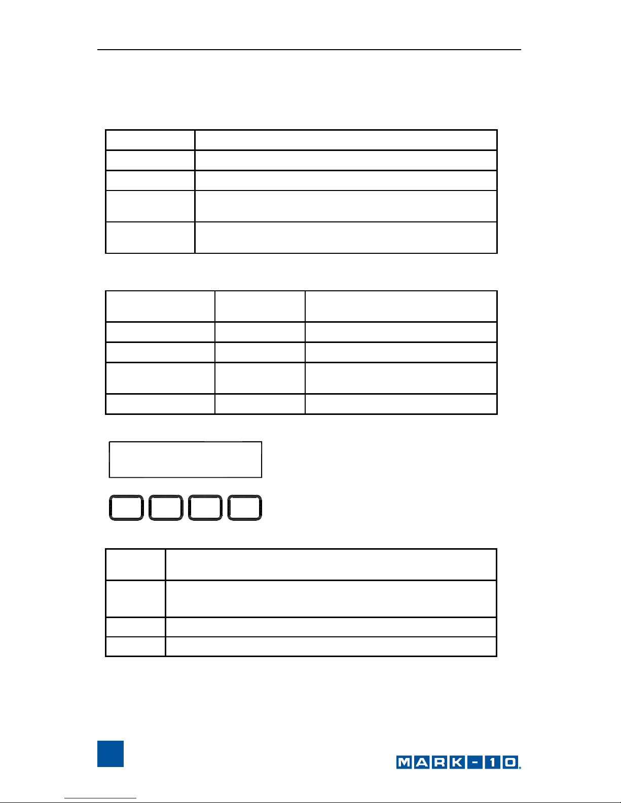
5.1 Speed
Independent speeds can be set for both directions of movement. The
parameters are labeled as follows:
Default speed settings and available speeds are as follows:
Test stand Parameter labels
ESMH L SPEED, R SPEED
ESM UP SPEED, DN SPEED
TSFM500 /
TSFM500H
UP SPEED, DN SPEED
TSTM /
TSTMH
CW SPEED, CCW SPEED
Test stand Default
speed
ESMH 10 in/min
ESM 10 in/min
TSFM500 /
TSFM500H
5 in/min
TSTM / TSTMH 6 RPM
Available settings
in/min [mm/min]
0.2 - 50 [5 - 1270]
0.02 - 36 [0.5 - 900]
0.01 - 6 [0.2 - 150]
0.01 - 15 RPM [0.05 - 90°/s]
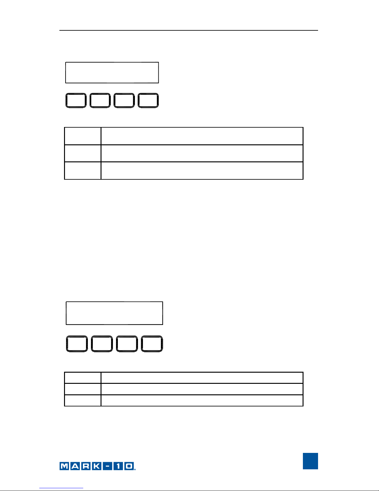
UP SPEED: 10 .7 3
ESC ENTR
+
_
+
Increments the speed setting. Holding down + will
increment at an increasingly faster rate.
–
Decrements the speed setting. Holding down – will
decrement at an increasingly faster rate.
ENTR
Returns to the Test Parameter Setup menu
ESC
Exits the parameter without saving changes
Page 11
User’s Guide
11
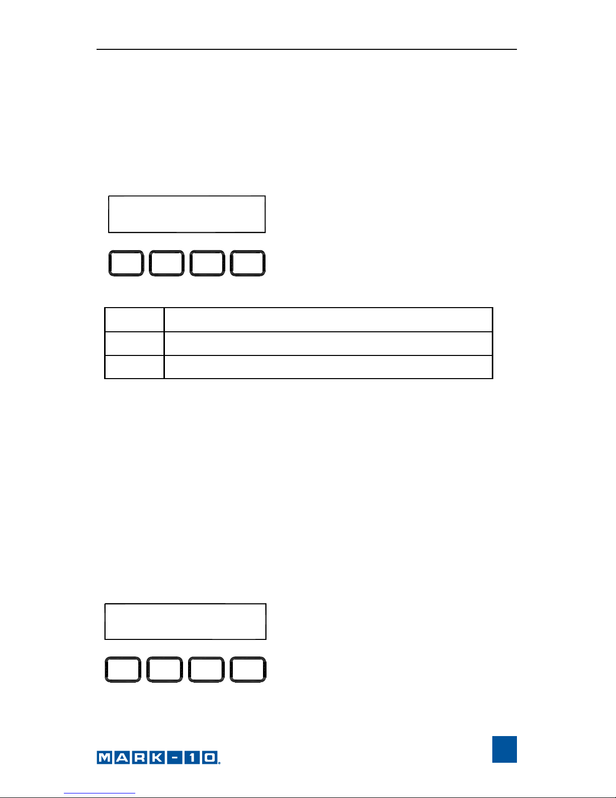
5.2 Auto Return (AUTO RETURN)
With this feature, the test stand moves to a limit switch, load set point, or travel
limit (TSTM / TSTMH only), whichever occurs first, and stops. Then, the test
stand returns to the other limit and stops. The test speed is dictated by the
independent speed settings. The return speed is always maximum sp eed.
Default setting: off
Available settings: off, on
Note: If AUTO RETURN is turned on, CYCLING is automatically turned off and
the KEYS parameter is automatically set to MAINTAINED mode. See following
pages for details on the CYCLING and KEYS parameters.
5.3 Cycling (CYCLES)
This setting allows the user to configure the number of cycles through which the
test stand will sequence. One cycle consists of the test stand moving to a limit
switch, load set point, or travel limit (TSTM / TSTMH only), whichever occurs
first, at the specified speed, stopping for the specified amount of dwell time, and
returning to the other limit at the specified speed.
Default setting: 00000 (off)
Available settings: 00000 – 99999
AUTO RETURN: of f
ESC ENTR
+
_
+ or –
Cycles through the available settings
ENTR
Returns to the Test Parameter Setup menu
ESC
Exits the parameter without saving changes
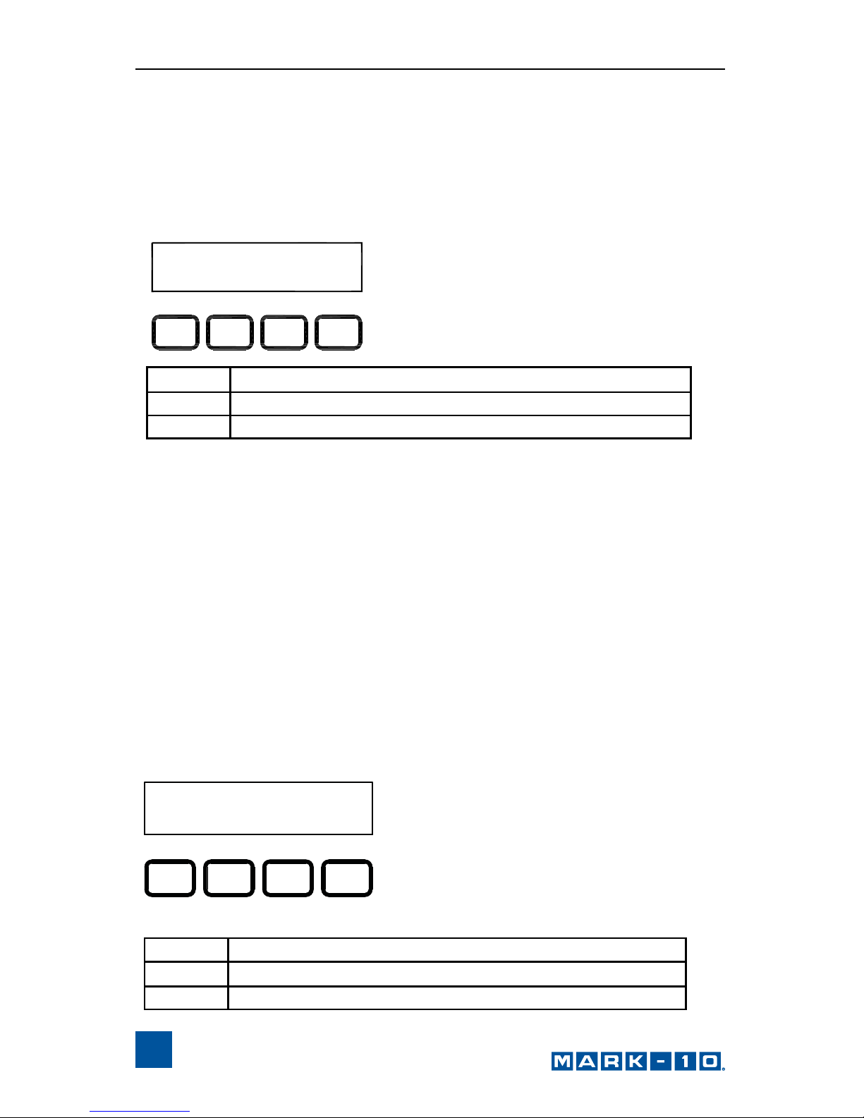
CYCLES:
00000
ESC ENTR
+
_
Page 12

Series DC Digital Controllers
12
5.4 Dwell Time
This setting corresponds to the amount of time, in seconds, for which the test
stand stops at the limit during a cycle sequence. Independent dwell times can
be set for both limits.
Note: the dwell time setting is unavailable for an auto return sequence.
Default setting: 0 (no dwell time)
Available settings: 0 – 9999.9
+
Increases the number of cycles in
increments of 1. Holding down + will
increment at an increasingly faster rate. If
99999 is reached the next number will be
00000 and continue incrementing.
–
Decreases the number of cycles in
increments of 1. Holding down – will
decrement at an increasingly faster rate. If
00000 is reached the next number will be
99999 and continue decrementing.
Press and hold
+ and –
simultaneously
If pressed and held for two seconds or
longer the number of cycles will change to 0.
ENTR
Returns to the Test Parameter Setup menu
ESC
Exits the parameter without saving changes
DWELL U: 0000.0
ESC ENTR
+
_
Page 13

User’s Guide
13
5.5 CW and CCW Travel Limits (CW L and CCW L)
Applies to TSTM / TSTMH only
This setting corresponds to the rotational travel distance the test stand moves
before stopping or cycling. CW and CCW limits are programmed indivi dually.
The programmed distances are relative to the zero position of the test stand.
The travel indicator can be zeroed by pressing and h olding STOP for three
seconds.
Default setting: 1 revolution
Available settings: ±2,777.77 revolutions
+
Increases dwell time in increments of .1 sec. Holding
down + will increment at an increasingly faster rate. If
9999.9 is reached the next number will be 0 and continue incrementing.
–
Decreases dwell time in increments of .1 sec. Holding
down – will decrement at an increasingly faster rate. If
0 is reached the next number will be 9999.9 and continue decrementing.
ENTR
Returns to the Test Parameter Setup menu
ESC
Exits the parameter without saving changes
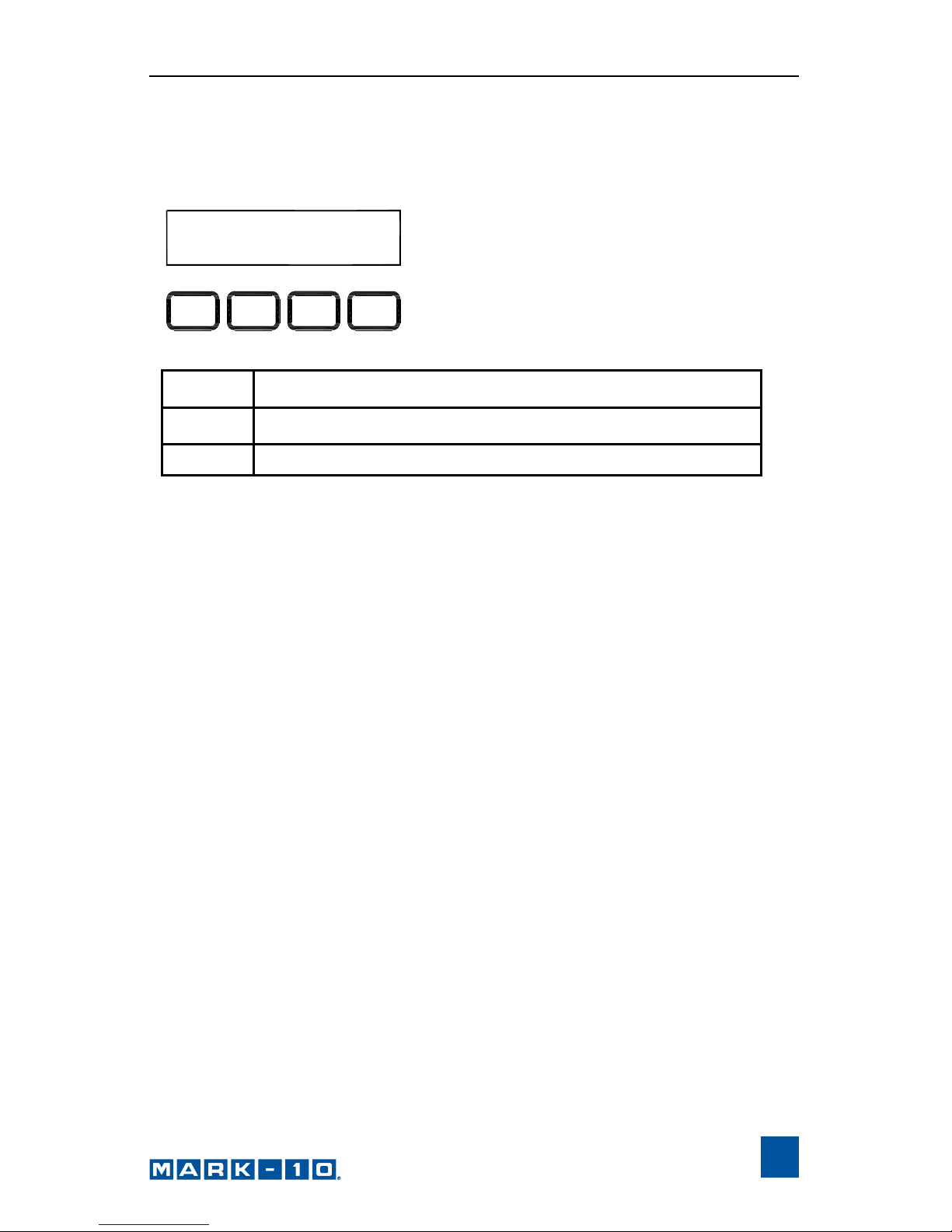
CW L:
000040.7
ESC ENTR
+
_
+
Increases the travel limit setting. Holding down + will
increment at an increasingly faster rate.
ENTR
Returns to the Test Parameter Setup menu
ESC
Exits the parameter without saving changes
–
Decreases the travel limit setting. Holding down – will
increment at an increasingly faster rate.
Page 14

Series DC Digital Controllers
14
5.6 Overload Analog Output Voltage (OVRLOAD V)
This setting corresponds to the full scale analog voltage output of the force or
torque gauge. Series DC controllers protect gauges from overload by
measuring incoming analog voltage and stopping test stand motion when the
programmed percentage of full scale has been reached (see Section 5. 7). The
value for Mark-10 gauges is ±1V. Adjustable voltage allows for compatibility
with other brands as well.
Default setting: OFF
Available settings: ±1V, ±2V, ±4V, OFF
5.7 Overload Settings (C OVERLOAD and T OVERLOAD or
CW OLOAD and CCW OLOAD)
The setting corresponds to the percentage of full scale of the force or torque
gauge at which test stand travel stops. For example, a setting of 80% for a 50 lb
capacity force gauge would stop test stand motion when 4 0 lb is reached.
Independent settings may be programmed for both load directions (tension and
compression, or CW and CCW).
Note: For force test stands, when the crosshead is moving in the UP direction,
only the tension overload setting applies. W hen the crosshead is moving in the
DOWN direction, only the compression overload setting applies. The same
concept applies to the CW and CCW directions for torque test stands.
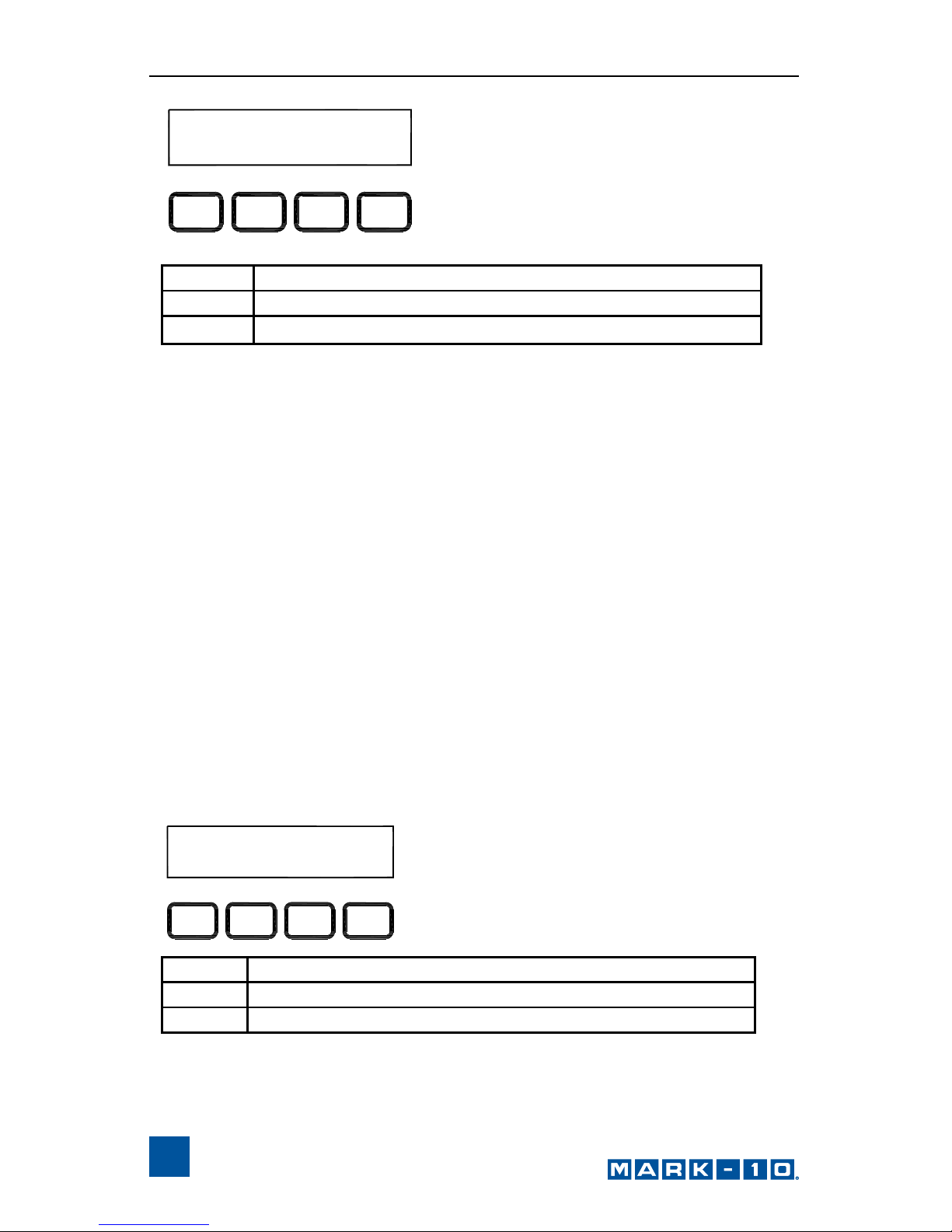
OVRLOAD V:
+/-1
ESC ENTR
+
_
+ or –
Cycles through the available settings
ENTR
Returns to the Test Parameter Setup menu
ESC
Exits the parameter without saving changes
Page 15
User’s Guide
15
Default setting: 100%
Available settings: 20% - 100% (10% increments)
5.8 Control Source (CONTROL)
This setting corresponds to the source of test stand control. The default value
CONSOLE sets the test stand to accept commands only from the controller.
Any external commands received through the serial port are ignored.
PC refers to external control via serial communication. If any parameters are
changed on the front panel, these settings will be ignored, exc ept for Auto
Return or Cycling. If either of these parameters are turned on, PC control will
be turned off.
Default setting: CONSOLE
Available settings: CONSOLE, PC
C OVERLOAD:
20%
ESC ENTR
+
_
+ or –
Cycles through the available settings
ENTR
Returns to the Test Parameter Setup menu
ESC
Exits the parameter without saving changes
CONTROL:
ESC ENTR
+
_
CONSOLE
+ or –
Cycles through the available settings
ENTR
Returns to the Test Parameter Setup menu
ESC
Exits the parameter without saving changes
Page 16
Series DC Digital Controllers
16
5.9 Baud Rate (BAUD RATE)
This setting corresponds to the baud rate setting of the computer program
controlling the test stand.
Default setting: 19200
Available settings:
1200, 2400, 4800, 9600, 19200, 38400, 57600, 115200
5.10 Stop Bits and Parity (STOP & PAR)
This setting corresponds to the stop bits and parity settings of the computer
program controlling the test stand.
Default setting: 8-1n
Available settings:
8-1E 8 stop bits, 1 stop bit, even parity
8-1o 8 stop bits, 1 stop bit, odd parity
8-1n 8 data bits, 1 stop bit, no parity
8-2n 8 data bits, 2 stop bits, no parity
7-1E 7 data bits, 1 stop bit, even parity
7-1o 7 data bits, 1 stop bit, odd parity
7-2E 7 data bits, 2 stop bits, even parity
7-2o 7 data bits, 2 stop bits, odd parity
7-2n 7 data bits, 2 stop bits, no parity
BAUD RATE:
9600
ESC ENTR
+
_
+ or –
Cycles through the available settings
ENTR
Returns to the Test Parameter Setup menu
ESC
Exits the parameter without saving changes
+ or –
Cycles through the available settings
ENTR
Returns to the Test Parameter Setup menu
ESC
Exits the parameter without saving changes
STOP & PAR:
8-1n
ESC ENTR
+
_
Page 17
User’s Guide
17
5.11 Units of Speed (UNITS)
Default setting: in/min or RPM
Available settings: in/min, mm/min or RPM, °/sec
5.12 Programmable Button Function (KEYS)
Three button function modes are available:
1. Maintained
The test stand will move continuously once the button has been
pressed. Subsequently pressing the UP, DOWN, or STOP during
a test will stop motion.
2. Momentary
The test stand will move only if the button is held down. Releasing
the button will stop movement immediately.
3. Auto
Holding down the button for more than 0.5 seconds will enter
momentary mode, at which time an audible indicator will sound
and the LED indicator on the button pushed will be illuminated. A
short tap on the button will operate the test stand in maintained
mode. Pressing UP, DOWN, or STOP during maintained mode
will stop motion.
Default setting: maintained
Available settings: maintained, momentary, auto
UNITS: mm/min
ESC NTRE
+
_
+ or –
Cycles through the available settings
ENTR
Returns to the Test Parameter Setup menu
ESC
Exits the parameter without saving changes
Page 18
Series DC Digital Controllers
18
5.13 Default Settings (DEFAULT?)
This setting provides a quick return to factory settings, as follows:
UP SPEED: Depends on test stand
DN SPEED: Depends on test stand
AUTO RETURN: off
CYCLING: 00000 (off)
CW L: 1 revolution
CCW L: 1 revolution
OVERLOAD V: OFF
OVERLOAD: 100%
CONTROL: CONSOLE
BAUD RATE: 19200
STOP & PAR: 8-1n
UNITS: Depends on test stand
PASSWORD: 0000 (off)
KEYS: maintained
Default setting: off
Available settings: off, on
KEYS: m a i n t a i n e d
ESC ENTR
+
_
+ or –
Cycles through the available settings
ENTR
Returns to the Test Parameter Setup menu
ESC
Exits the parameter without saving changes
DEFAULT?: N O
ESC ENTR
+
_
+ or –
Cycles through the available settings
ENTR
Returns to the Test Parameter Setup menu
ESC
Exits the parameter without saving changes
Page 19

User’s Guide
19
5.14 Password (NEW PWORD)
If desired, a password can be set to prevent unwanted changes to test
parameters. The password can be set to any number between 0000 and 9 999.
The default setting of 0000 indicates that the password is disabled, and that the
user can freely enter the Test Parameter Setup menu. If misplaced or forgotten,
the password may be reset. Contact Mark-10 for instructions.
Default setting: 0000 (off)
Available settings: 0000 – 9999
NEW PWORD:
0000
ESC ENTR
+
_
+
Increases the number in increments of 1. Holding
down + will increment at an increasingly faster rate. If
9999 is reached the next number will be 0000 and
continue incrementing.
–
Decreases the number in increments of 1. Holding
down – will decrement at an increasingly faster rate. If
0000 is reached the next number will be 9999 and
continue decrementing.
ENTR
Returns to the Test Parameter Setup menu
ESC
Exits the parameter without saving changes
Page 20
Series DC Digital Controllers
20
6 OPERATING MODES
6.1 Mode Overview
Series DC controllers can be operated in three modes:
1. Basic Mode
Manual control of test stand movement.
2. Auto Return Mode
Test stand moves to a limit switch, load set point, or travel
distance (TSTM / TSTMH only), whichever occurs first, then
reverses and moves at maximum speed to the other limit,
whichever occurs first.
3. Cycling Mode
Test stand cycles between limits at the selected speed, and
pauses at each limit for a selected period of time.
4. PC Mode
Test stand is controlled through a serial connection with a
computer.
The Operating Mode screen appears as follows:
On the TSTM / TSTMH test stands, the screen appears as follows:
The item selected will be capitalized, as shown in the figure above. The set
speed can be changed in Test Parameter Setup. Independent speeds may be
programmed for each direction.
men
u
min maxSET
S p e e d :
.000
men
u
min maxSET
1 . 2 7 5
.
000
TRAVEL
SPEED
Page 21
User’s Guide
21
6.2 Menu Navigation
At power-up, the display will show the operation screen for whichever mode
was used last. The display will appear as one of the following:
Basic & Auto Return Modes:
Cycling Mode:
PC Mode:
Appears the same as in Basic and Auto Return modes.
Pressing menu will enter Test Parameter Setup. If a password has been
programmed, the display will prompt the following:
The password is a four digit number. The first digit in the password will be
flashing, signifying that it is active and can be incremented by pressing +. To
advance to the next digit, press –>. Change subsequent digits in the same
fashion. Once the complete password has been entered, press ENTR. If
correct, the display will enter Test Parameter Setup Mode. If the password is
incorrect, the words INCORRECT PASSWORD will flash, and the display will
revert to Operating Mode.
men
u
min maxSET
S p e e d :
.
000
menu min max SET
C Y C L E S : 0 0 0 2 4
PASSW 0ORD: 000
ESC > NTRE
_
+
Page 22

Series DC Digital Controllers
22
6.3 Basic Mode
The test stand moves in the direction indicated by the UP and DOWN buttons.
When the test stand is in motion, an LED indicator on the button pushed will be
illuminated. The KEYS setting controls how test stand movement responds to
the push of the UP and DOWN buttons. The three settings are:
1. Maintained (default)
The test stand will move continuously once the button has been
pressed. Subsequently pressing STOP during a test will stop
motion.
2. Momentary
T he test stand will move only if the button is pressed and held.
Releasing the button will stop movement immediately.
3. Auto
Holdin g down the button for more than 0.5 seconds will enter
Momentary mode, at which time an audible indicator will sound
and the LED indicator on the button pushed will be illuminated. A
short tap on the button will operate the test stand in Maintained
mode. Pressing STOP during Maintained mode will stop motion.
To resume the test, press UP or DOWN again.
Pressing EMERGENCY STOP will immediately stop motion in any
mode. To release, twist the button counter-clockwise until it
assumes its original position. To resume the test, press UP or
DOWN.
The test stand will move until a limit switch, load set point, or travel distance set
point (TSTM / TSTMH only) has been reached. If the test stand has stopped at
a load set point or travel distance set point, the limit condition may be
overridden by pressing and holding UP or DOWN for two seconds.
6.3.1 Travel Indication (TSTM / TSTMH only)
Travel indication is displayed in the upper left corner of the display, as sh own in
Section 6.1. The displayed units are the same as configure d in the UNITS
parameter. Indicated travel is a relative value. To zero out travel distance,
ensure that the test stand is not in motion, then press and hold STOP for three
seconds. If the cable connecting the angle encoder to the rear of the controller
is unplugged, the error message ENCODER ERROR will appear. To clear the
message, insert the cable, then press STOP.
6.3.2 Limit Switch Operation
Note: limit switches are standard on the ESMH test stand, and are optional on
the ESM and TSFM500 / TSFM500H test stands. Not applicable for TSTM /
TSTMH test stands.
Limit switches allow the operator to set a location along the column at which
point the crosshead will stop moving. Adjust the switches’ positions by
Page 23

User’s Guide
23
loosening, repositioning, and re-tightening the thumb screws.
Note: the distance between limit switches must be at least 0.2 in [5 mm].
6.3.3 Overload Protection
The 09-1143 cable is required for overload protection of a Mark-10 gauge. If
overload protection is enabled, the test stand will stop when the programmed
percentage of full scale of the gauge has been reached.
When overload protection is enabled, if the 09-1143 cable is discon nected, and/
or if the force gauge is turned off, the error message GAUGE ERROR will
appear. Plug in the cable and/or turn on the force gauge to clear the mess age.
Note: For force test stands, when the crosshead is moving in the UP direction,
only the tension overload setting applies. W hen the crosshead is moving in the
DOWN direction, only the compression overload setting applies. The same
concept applies to the CW and CCW directions for torque test stands.
6.4 Auto Return Mode
With this setting, the test stand moves to a limit switch, load set point, or travel
distance (TSTM / TSTMH only), whichever occurs first, and stops. Then, the
test stand returns at maximum speed to the other limit, whichever occurs first,
and stops. The speed at which the test stand travels is dictated by the
independent speed settings.
The test stand can be stopped at any time during an Auto Return sequence by
pressing STOP. To resume the test, press UP or DOWN.
If the test stand has stopped at a load set point or travel distance set point, the
limit condition may be overridden by pressing and holding UP or DOWN for two
seconds.
Travel indication and limit switch operation is the same as in Basic Mod e
.
6.4 Cycling Mode
This mode cycles the test stand between limit switches, load set points, or
travel distance set points (TSTM / TSTMH only), whichever occurs first. One
cycle consists of the following steps:
1. Test stand moves to a limit at the specified speed.
2. Test stand stops for the specified amount of dwell time.
3. Test stand reverses direction, returns to the other limit at the
specified speed, and stops.
A cycling sequence can be initiated from any position and can start in either
direction. If the test stand is at a limit, however, cycling can only be started in
the direction of the other limit. To initiate a cycle sequence, press UP or DOWN.
During a cycle sequence, a counter will be displayed, indicating the number of
cycles remaining, as shown below:
Page 24
Series DC Digital Controllers
24
As in Basic Mode, the min, max, and set soft keys are active during crosshead
movement. When the cycling sequence has ended and the test stand has
stopped at a load set point or travel distance set point, the limit condition may
be overridden by pressing and holding UP or DOWN for two seconds.
6.4.1 Dwell time
Dwell time is the amount of time, in seconds, for which the test stand stops at a
limit during a cycle sequence. When the test stand has reached a limit, a
counter will be displayed, shown as follows:
If the DWELL U and/or DWELL L settings are set to 0, the test stand will
immediately reverse direction upon reaching the corresponding limit, and no
counter will be displayed.
The cycle sequence may be interrupted before it has been compl eted b y
pressing STOP. A soft key labeled RESET will appear as follows:
CYCLES: 00024
menu
S E T
m i n
m a x
DWELL: 0001.5
menu
S E T
m i n
m a x
Page 25

User’s Guide
25
At this point, there are two options:
1. Canceling the cycle sequence:
Press RESET to stop and reset the cycle
sequence. The cycle counter will revert to
the number of cycles originally
programmed.
2. Resuming the cycle sequence:
Press UP or DOWN to resume.
Once the sequence has been completed, the screen will revert to the number of
cycles programmed originally. To begin another cycle test, press UP or DOWN.
Travel indication and limit switch operation is the same as in Basic Mod e.
6.5 PC Mode
The test stand may be controlled by a computer through the Series DC
controller via serial communication. A list of supported ASCII commands is
provided below. All commands must be lowercase.
Note: Functions relating to distance measurement (indicated with an asterisk)
are applicable only with the TSTM / TSTMH stands.
a Request speed
b Set travel units to inches or revolutions
c Enter cycle mode
d Move down or CCW
e Set speed (ex. e10.00 = 10.00 in/min)
f Set cycles (ex. f0500 = 500 cycles)
g* Set lower travel limit (ex. g90.0 = 90 degrees)
h* Set upper travel limit (ex. h180.0 = 180 degrees)
i Set travel units to millimeters or degrees
j Set speed to maximum speed
k Set speed to minimum speed
l* Enter travel limit mode
m Enter manual mode
n* Transmit travel and torque readings
o Set speed to programmed speed
p** Request stand status**
q Request number of cycles completed
r Request number of cycles set
s Stop
t Reset cycle counter to zero
u Move up or CW
v* Request upper travel limit
w* Request lower travel limit
x* Request travel value
z* Reset travel to zero
*Applicable only to the TSTM / TSTMH test stands.
** The transmission of ASCII “p” will return the stand status.
CYCLES: 00024
R E S E T
Page 26

Series DC Digital Controllers
26
The following are the return codes and their definitions
Test stand status U = Moving up or CW
D = Moving down or CCW
S = Stopped
Operating mode C = cycle mode
L = limit mode
M = manual mode
Limit switch status UL = crosshead at upper limit
DL = crosshead at lower limit
Commands relating to Mark-10 force and torque gauges are NOT the same as
indicated in the respective user’s guides. A list of supported ASCII commands is
provided below. All commands must be uppercase:
A Displays current unit
F Toggles between Normal and Data Collect modes
P Steps through Normal mode, Tension/CCW Peak
mode, and Compression/CW Peak mode
R Zeroes the gauge (zeroes all modes)
S Sends currently selected mode (Normal, Tension/
CCW Peak, Compression/CW Peak, or Data Collect)
U Steps through units
X or ? Sends currently displayed reading
Y Enables RS-232 output and sends continuous data
stream when in Data Collect mode
Z Zeroes the currently selected mode
The 09-1143 cable is needed to communicate between a Mark-10 gauge and the
controller.
The 09-1056 serial cable is needed to communicate between a computer and the
controller. Baud rate, stop bits and parity must be programmed in the stand to
correspond with the computer program’s settings. Details on this are provi ded in
Section 5.
While in PC control, if any parameters are changed on the controller, these settings
will be ignored, except if Auto Return or Cycling are turned on. If so, PC control will
be turned off automatically.
Page 27

User’s Guide
27
7 COMMUNICATING WITH MESURGAUGE
Series DC controllers can communicate with MESURgauge data collection
software. The test stand can output either load data only or load data combined
with travel data. To communicate with MESURgauge, certain settings in the test
stand, gauge, and software must be changed as follows:
7.1 Load data only
1. Check physical connections (refer to Section 3.2).
2. Gauge settings (refer to the gauge’s user’s guide).
1. Set to automatic output of every sample.
2. Disable Mitutoyo BCD output.
3. Test stand settings
1. Set the baud rate to 115,200.
2. Set the Control mode to Console.
7.2 Load and travel data simultaneously (TSTM / TSTMH only)
1. Check physical connections (refer to Section 3.2)
2. MESURgauge settings
1. Test Setup tab
1. Under Travel check the Enable box. Under Reading
Mode, if Continuous Readings is selected, Readings per
Sec. defaults to 4. This value can be increased.
2. Port Configuration tab
1. Identify a working com port, and select the appropriate
port in Gauge Port Settings.
2. Under Gauge Port Settings, change baud rate to 115,200.
3. Under Reading Request String change String to Write to
“n” (lowercase, no quotes). Uncheck the CR box.
4. Check the box labeled Travel Data Combined with Load
Data. No changes are needed to the default lines, fields,
and delimiter.
Page 28

Series DC Digital Controllers
28
5. Click APPLY after making any changes in the Gauge Port
Settings area.
3. Gauge settings (refer to the gauge’s user’s guide)
1. Set to automatic output of every sample.
2. Disable Mitutoyo BCD output.
4. Test stand settings
1. Set the baud rate to 115,200.
2. Set the Control mode to Console.
5. The Gauge Settings tab and all other gauge-related functions
cannot be used while MESURgauge is connected to the DC controller.
It is intended for use only when connected to a Mark-10 gauge
directly.
Page 29
User’s Guide
29
8 SPECIFICATIONS
* Applicable only to the TSTM / TSTMH stands.
9 DIMENSIONS in [mm]
Load capacity Depends on test stand
Standard speed range Depends on test stand
Speed setting accuracy ±0.2%
Speed variation with load ±0% [Stepper motor driven]
Travel accuracy:* ±0.7°
Travel repeatability:* 0.01 rev / 0.1°
Travel resolution:* 0.01 rev / 0.1°
Power Universal input 80-240 VAC, 50/60 Hz
Fuse type 1.2 A, 250V, 3AG, SLO BLO
Weight 11 lbs [5.0 kg]
6.50 [165.0]
4.20 [106.7]
13.20 [335.3]
WARRANTY
Mark-10 Corporation expressly warrants to its buyer for three (3) years from the date of
delivery that the goods sold are free from defects in workmanship and materials. Mark-10
Corporation will, at its option, repair or replace or refund the purchase price of goods
found to be defective. This remedy shall be the buyer’s sole and exclusive remedy. Any
modification, abuse, exposure to corrosive environment or use other than intended will
void this warranty. This warranty is in lieu of all other warranties, including implied warranties of merchantability and fitness for an intended purpose. In no event shall Mark-10
Corporation be liable for any incidental and consequential damages in connection with
goods sold or any part thereof.
Page 30

Series DC Digital Controllers
30
NOTES:
Page 31
User’s Guide
31
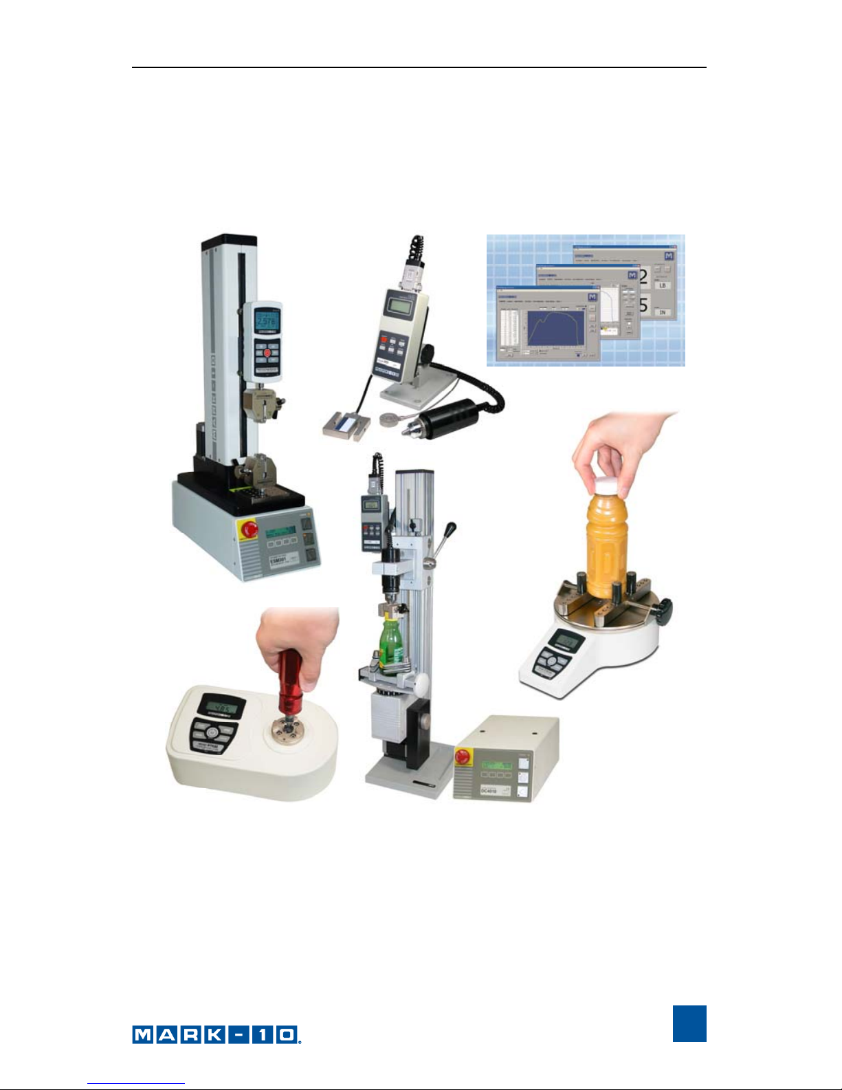
OTHER MARK-10 PRODUCTS
A full line of force and torque measurement products and related items,
including force gauges, torque gauges, force and torque test stands, sensor s,
grips, software, and more.
Page 32

32-1101
REV 2 0710
Mark-10 Corporation has been an innovator in the Force and Torque
measurement fields since 1979. We strive to achieve 100% customer
satisfaction through excellence in product design, manufacturing an d
customer support. In addition to our standard line of products we can
provide modifications and custom designs for OEM ap plications. Our
engineering team is eager to satisfy any special requirem ents. Please
contact us for further information or suggestions for improvement.
We make a measurable difference in force and torque measurement
Mark-10 Corporation
11 Dixon Avenue
Copiague, NY 11726 USA
1-888-MARK-TEN
Tel: 631-842-9200
Fax: 631-842-9201
Internet: www.mark-10.com
Email: info@mark-10.com
 Loading...