

Page 1
AC1086 / AC1086-1 Safety Shield - Assembly Instructions
The AC1086 safety shield is designed for Models F105, F305, and F505
test frames. AC1086-1 is designed for Model ESM303. When properly used,
they can protect the operator against the dangers of airborne debris resulting from force testing. Follow these assembly and usage instructions:
Installing the External Emergency Switch Connector Models F105 / F305 / F505
This process is required only if the shield is ordered separately from the
test frame. If ordered simultaneously, the connector is factory-installed.
This process involves the handling sensitive electronic components. We recommend proceeding only if you have experience
working with electronics. Mark-10 oers a factory retrot.
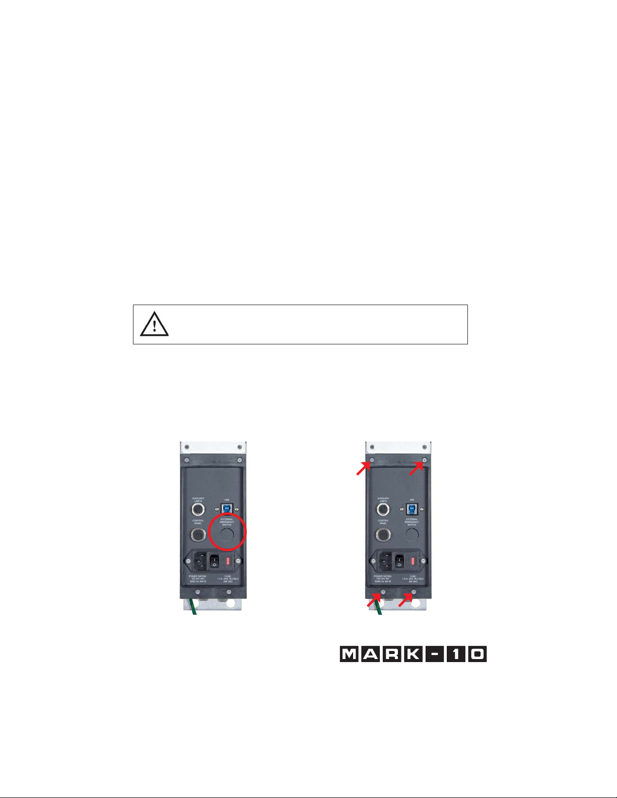
1. Remove the MDU. Refer to the test
frame’s user’s guide for details.
2. Punch out the opening below the
label, “EXTERNAL EMERGENCY
SWITCH”, as highlighted below:
3. Remove the back panel from
the MDU housing with four
screws, as highlighted below:
Find Quality Products Online at: sales@GlobalTestSupply.com
www.GlobalTestSupply.com
Page 2
AC1086 / AC1086-1 Safety Shield - Assembly Instructions
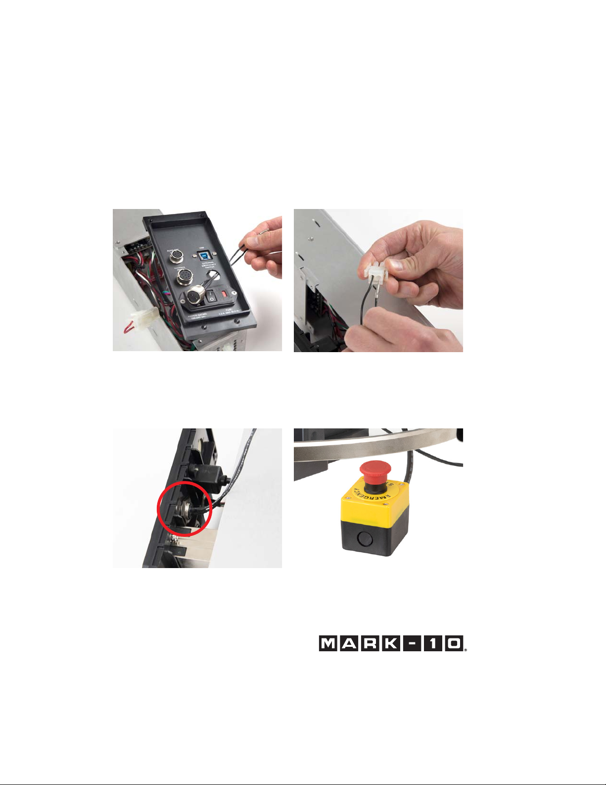
4. Route the two wires from the rear
of the connector through the hole,
as shown below:
6. Install the connector to the housing
by inserting the spacer over the
body of the connector, then tightening the nut, as shown below:
5. Connect the two cables to the
white mating plug, as shown below:
7. Reassemble the MDU and reinstall.
8. Connect the cable from the remote
emergency stop switch, shown
below:
Find Quality Products Online at: sales@GlobalTestSupply.com
www.GlobalTestSupply.com
Page 3

AC1086 / AC1086-1 Safety Shield - Assembly Instructions
Installing the Shield - All Test Frame Models
1. The safety shield is shipped fully assembled. Remove it from the box and
remove the protective packaging.
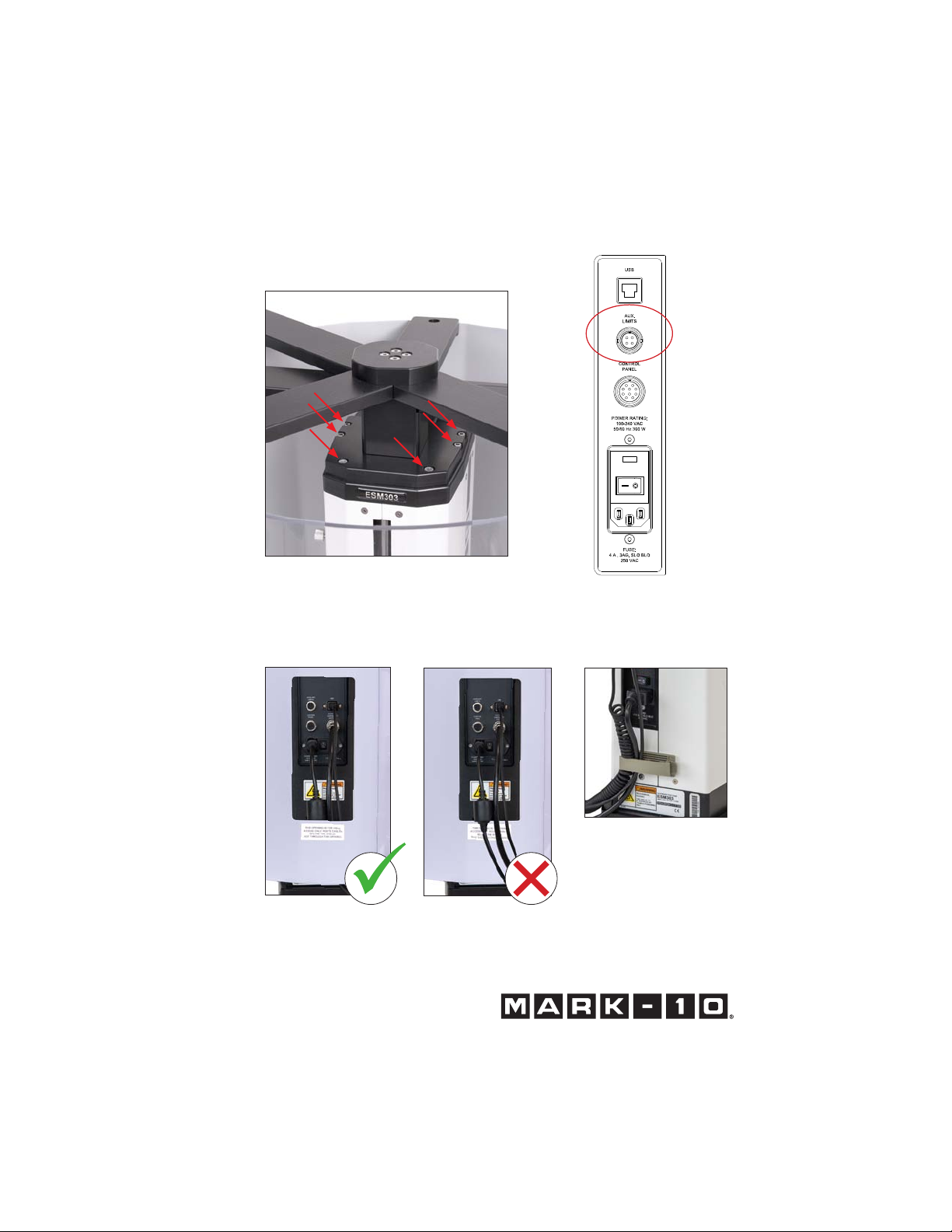
2. Position the mounting bracket on top of the column, aligning the thru holes
with the corresponding threaded holes at the top of the column. Fasten the six
provided socket head screws, as shown in Fig. 1.
3. Plug the interlock cable into the corresponding connector in the rear of the
column, labeled “AUX. LIMITS”, as shown in Figs. 2 and 3.
4. Route all cables, such as the power cable and control panel cable, underneath
the shield, as shown in Fig. 3. Do not route cables through the cutout in the
sheet metal cover. Doing so can result in damage to the cables while the door
is rotating past this area. This cutout is provided for hand access to the connector panel only.
5. The door may be opened in the clockwise or counter-clockwise direction.
Magnetic detents are provided for the closed position. If the interlock cable is
plugged in, the test stand’s control panel will indicate when the door is open
and prohibit movement. However, the FollowMe® function may be used to
adjust the crosshead position for sample loading.
Note for Model ESM303:
The following minimum test stand firmware versions are required:
Front: 2.02.08
Main: 2.02.07
With prior rmware versions, the FollowMe
door is open, however, the Auto Return function can still be used to return the
crosshead to the home position automatically. Contact Mark-10 for upgrade instructions. For further instructions refer to the test frame’s user’s guide.
®
function will not operate while the
Find Quality Products Online at: sales@GlobalTestSupply.com
www.GlobalTestSupply.com
Page 4
AC1086 / AC1086-1 Safety Shield - Assembly Instructions
Fig. 1
Attaching the shield assembly to
the top of the column
Fig. 3
Proper cable routing. Shown above:
Models F105 / F305 / F505
Fig. 2
Model ESM303 rear connectors
Fig. 4
Adhesive-backed
guide is included for
cable management
Find Quality Products Online at: sales@GlobalTestSupply.com
www.GlobalTestSupply.com
 Loading...