

Page 1

Mark-10 Corporation expressly warrants to its buyer for three (3) years
from the date of delivery that the goods sold are free from defects in
workmanship and materials. Mark-10 Corporation will, at its option,
repair or replace or refund the purchase price of goods found to be
defective. This remedy shall be the buyer’s sole and exclusive remed y.
Any modification, abuse, exposure to corrosive environment or use
other than intended will void this warranty. This warranty is in li eu of a ll
other warranties, including implied warranties of merchantability and
fitness for an intended purpose. In no event shall Mark-10 Corporat ion
be liable for any incidental and consequential damages in connect ion
with goods sold or any part thereof.
WARRANTY
User’s Guide
11-1042 OVERLOAD PROTECTION MODULE
09-1090 SET POINT CABLE
Page 2
11-1042 OVERLOAD PROTECTION MODULE
11-1042 / 09-1090
SETTING UP
Both the 11-1042 overload protection module and 09-1090 share the
same dual connectors. Each connector is marked and should be configured as follows:
A B
ESM, ESMH, TSTMH TSTM, TSFM500, TSFM500H,
TSFM1000, TSFM1000H
Test stand
model
This device is designed to prevent accidental overload to a Mark-10
gauge or sensor when used with any Mark-10 motorized test st and.
Applicable gauges are the BG, BGI, CG, and EG (if equipped with
optional outputs package). The module operates in both force and
torque applications.
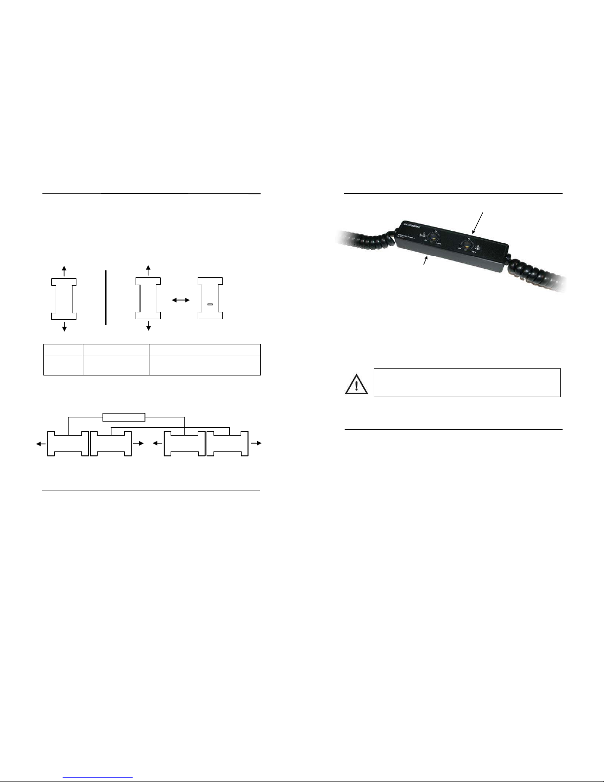
Set the percentage of full scale of the gauge or sensor at which the
test stand is to stop moving by adjusting the two potentiometers on th e
module with a Philips screwdriver. The percentage range is 20 - 110%
of full scale. See the illustration on the following page.
GAUGE
GAUGE
PC
PC
11-1042 09-1090
11-1042
09-1090
11-1042 MODULE
TO OUTPUT
CABLE
(OPTIONAL)
STAND
STAND
LIMITS
LIMITS
TO LIMIT
SWITCH
CABLE
(OPTIONAL)
TO TEST
STAND
TO
GAUGE
If using the overload protection module and 09-1090 set point cable
simultaneously, they should be configured as follows:
GAUGE
PC
TO
GAUGE
TO OUTPUT
CABLE
(OPTIONAL)
STAND
LIMITS
TO TEST
STAND
TO LIMIT
SWITCH
CABLE
(OPTIONAL)
REVERSE
A B
SELECT A OR B
ACCORDING TO
THE TABLE BELOW
User’s Guide
T / CCW
This setting applies to the tension
or counter-clockwise motion of the
test stand.
C / CW
This setting applies to the
compression or clockwise
motion of the test stand.
Once the percentages have been set, set up the test sample and proceed with the motorized test. When the force or torque threshold has
been reached, the stand will stop moving, the module will pro duce a
constant audible tone and the indicator below the potentiom eter will be
lit. The tone and indicator light will not turn off until the force or t orque
decreases to below the threshold value.
Note: It is highly recommended that the first test be performed at low speed to ensure that the module is functioning properly.
09-1090 SET POINT CABLE
This cable is designed to stop the motion of any Mark-10 motorized
test stand travel at user-programmable set points with a BG, BGI, or
CG gauge. Refer to your gauge’s user’s guide for programming instructions.
Cable configuration instructions are provided on the previous page.
 Loading...