

Page 1
Technical manual
Technisches Handbuch
Livret technique
Technisch boek
Instrukcja techniczna
Manual tehnic
EN
DE
FR
NL
OptiTherm
0664011_R01
06 29 191
OptiTherm
06 29 191
PL
RO
Page 2

Contents
Warnings .............................................................................................................................................. page 3
1.0 General
1.1 Subject to change .............................................................................................................. page 3
1.2 General warnings .............................................................................................................. page 3
1.3 Type of thermostat and application .............................................................................page 3
2.0 Technical data
2.1 Technical data .................................................................................................................... page 4
2.2 Factory settings ................................................................................................................. page 5
3.0 Installation and initial starting
3.1 General .............................................................................................................................. page 5
3.2 Placing .................................................................................................................................. page 5
3.3 Cabling .................................................................................................................................page 6
3.4 Mounting and installation ................................................................................................ page 6
3.5 First initial operation ........................................................................................................ page 7
4.0 Operation
4.1 Explanation of buttons .....................................................................................................page 8
4.2 Explanation of display and symbols .............................................................................page 9
4.3 Frost protection ................................................................................................................page 10
4.4 Switching on/off the heating mode ...............................................................................page 10
4.5 Switching on/off the ventilation mode ......................................................................... page 10
4.6 Switching on/off the overtime timer (extend timer) ................................................ page 10
5.0 Change settings
5.1 Call user menu ..................................................................................................................page 11
5.2 User menu: Change temperature setting ..................................................................page 12
5.3 User menu: Set/change clock program ........................................................................ page 12
5.4 User menu: Set/change exception day ......................................................................... page 13
5.5 User menu: Call settings menu......................................................................................page 14
5.6 Settings menu: Change date/time ..................................................................................page 14
5.7 Settings menu: Change overtime timer settings ........................................................ page 15
5.8 Settings menu: Ventilator high/low ............................................................................... page 15
5.9 Settings menu: Heater high/low ....................................................................................page 16
5.10 Settings menu: Temperature sensor selection ..........................................................page 17
5.11 Settings menu: Calibrating thermostat / external sensor ........................................page 17
5.12 Settings menu: Change language ...................................................................................page 18
5.13 Settings menu: Switch on/off Summer/Winter time ................................................page 19
5.14 Settings menu: Info .......................................................................................................... page 19
5.15 Settings menu: Change pin code ...................................................................................page 20
5.16 Settings menu: Call service menu .................................................................................page 20
5.17 Service menu: Change on/off regulation (switch differentiation) .........................page 21
5.18 Recover factory values ....................................................................................................page 22
6.0 Messages and Malfunctions
6.1 Message ............................................................................................................................page. 23
6.2 Malfunction messages ......................................................................................................page 23
7.0 Scrap OptiTherm ......................................................................................................................page 24
Figures / Tables
[1] Table of cable diameters and max. length of cabling ................................................ page 99
[2] Overview - connecting thermostat .............................................................................. page 99
[3] Connecting OptiTerm to one or more air heaters .................................................. page 100
[4] Correctly addressing OptiTherm ................................................................................page 101
[5] Setting dip switches and S4 air heater switch ........................................................... page 102
Quick start .............................................................................................................................................page103
2
Page 3

Read this document before
installing the appliance
Warning
Incorrect installation, adjustment, alteration, repair or maintenance may lead to material
damage or injury. All work must be carried out by approved, qualied professional. If the appliance is not positioned in accordance with the instructions, the warranty shall be rendered
void. This appliance is not intended for use by people (including children) who suffer from a
physical, sensory or mental handicap, or who are inadequately knowledgeable or experienced,
unless they are supervised or have received instruction in the use of the appliance from a person who is responsible for their safety. Children must be supervised to ensure that they do
not play with the appliance.
If in this technical book there is a reference to an image or table, then a gure is stated between
square brackets , for example [3]. The number refers to the images and tables with the number
stated in this technical book.
1.0 General
1.1. Subject to change
The manufacturer has a policy of continuous product improvement and reserves the right to make
changes to the specications without prior notice. The technical details are considered correct
but do not form the basis for a contract or warranty. All orders are accepted subject to the standard terms and conditions of sale and delivery (which will be sent to you at your request).
1.2 General warnings
Installation must comply with the relevant local and/or national regulations. Therefore allow the
OptiTherm to be installed by a professionally competent and qualied electrician taking account of
the national and international regulations. Faulty installation, adjustment, alteration, maintenance
activity or repair shall render the warranty void.
1.3 Type of thermostat and application
The OptiTherm is a digital clock thermostat with internal room sensor with which 1 or more air
heaters (type G(N)SD or G(N)CD), up to a maximum of 8, can be controlled on the basis of the
room temperature by means of a bus system.
The OptiTherm provides:
•
The possibility of switching on/off the heating mode.
•
The possibility of switching off/off the ventilator of the air heater(s).
•
The possibility to signal and to rectify malfunctions
•
A year clock with 20 program blocks
•
The possibility to program exception days on date.
•
The possibility to regulate between 4 different methods of operation
(DAY, ECO, NIGHT, FROST).
3
EN
Page 4

•
An overtime timer for switching to a different operating mode outside the switching times.
•
Pin code protection to protect settings such as temperature, clock program, etc.
•
A frost protection which automatically switches on the air heaters when the temperature falls
too low.
2.0 Technical data
2.1 Technical data
•
Type designation : OptiTherm
•
Type of thermostat : Digital clock thermostat
•
Item number : 06 29 191
•
Connection : Bus system (2 Wires)
•
cabling : Protected bus cable, see also §3.3
•
Switch differential : 1K
•
Dimensions : 129 x 129 x 20mm (lxwxh)
•
Weight : 188 grammes
•
Protection class : IP30
•
Ambient temperature : 0 - 40º
•
Temperature setting : 0 to 40º, in increments of 0.5º
•
Clock program : 20 program blocks
Mon-Fri , Tues-Fri, Sat-Sun, daily or per day
•
Exception days : 20 program blocks
Switch to day, eco or night temperature
•
overtime timer : Free setting range from 15 mins - 24 hrs
Switch to day, eco or night temperature
•
Calibrate temperature sensor : setting range from -3.0º to 3.0º
•
Room sensor : standard provision
•
External sensor : option of measuring the temperature per unit or on the basis
of an average value.
•
Time display : 24 hours
•
Summer / winter time : Adjustable automatic/off
•
Languages : Dutch, English, German, French, Polish, Romanian
4
Page 5

2.2 Factory settings
•
Temperature : Day 18°C
Eco 15°C
Night 08°C
Frost 05°C
•
Clock program : Program block 1
Day 12345
Switch time 08:00 >> 17:00
Switch to Day
•
Exception day : off
•
overtime timer : Maximum setting time 03:00hrs
Switch to Day
•
Ventilator high/low : Day High
Eco High
Night High
•
Heater high/low : Heater High
Differentiation 1.0K
•
Selection temperature sensor : Sensor Thermostat
•
Calibrate temperature sensor : 0.0°C
•
Summer / winter time : Automatic
•
Pin code : 1 0 0 0
3.0 Installation and initial starting
3.1 General
•
After unpacking check the OptiTherm and if also ordered, the external sensor(s) delivered with
it for damage.
•
At the same time check the correctness of the type/model
(Thermostat: OptiTherm 06 29 191, external sensor: Digital sensor conc. 2 Wires 0629194).
Contact the supplier if the thermostat is damaged or it is not the correct type/model.
3.2 Positioning
In order to determine an appropriate place to mount the OptiTherm you must consider the
points below:
– Place the OptiTherm in the room to be heated, because it is supplied with an internal room
sensor. This is not applicable when an external sensor (optional deliverable) connected to the air hea-
ter(s).
– Mount the OptiTherm in a draft free location
– Do not mount the OptiTherm on a cold wall/partition.
– Do not mount the OptiTherm directly in the airow of the air heater(s).
– It is advised to place the OptiTerm at a distance of ±1.5m from the oor.
5
EN
Page 6

3.3 Cabling
For the cabling a protected bus cable must always be applied.
Also see table [2] for the maximum length and the proper diameter.
Attention!
The cable protection is earthed on the air heater.
The bus cable must be selected according to the country specic rules, where the values which
are included in the technical data must be adhered to.
3.4 Mounting and installation
For the correct mounting and connection of the OptiTherm to the air heaters, you follow the
points below:
•
Check that the electricity supply is switched off. If that is not the case, then rst switch off the
electricity supply before you proceed. For this, also consult the technical manual of the air heater to be connected.
•
Mount the OptiTherm on the partition, taking into account §3.2 Placing the OptiTherm
•
Only applicable when external sensors are applied.
Mount the external sensors at the correct place. For this, also consult the instruction which is
delivered with the sensor.
•
Lay the correct cabling between the air heater and the OptiTherm and, if applicable, the air he-
aters with each other. For this also take into account §3.3 Cabling. [2][3]
•
Only applicable when external sensors are applied.
Lay the correct cabling between the air heater and the external sensor. For this also take into
account §3.3 Cabling and the instructions for the external sensor. [2][4]
•
Connect the OptiTherm and the air heater(s) according to the diagram [2][3]
•
Only applicable when external sensors are applied.
Connect the cable to the external sensor and the air heater and there also take into account
the instructions for the external sensor. [2][4]
•
Only applicable with the connection of more than one appliance on 1 OptiTherm.
Install the Dip switch and switch S4 on the automatic burner of the air heaters. For this, ensure
that the air heater to which the OptiTherm is connected is always addressed as appliance 1.
[5][6]
Cable type Application EIB specication
YCYM Fixed system Dry, damp, wet rooms
In the open air (no direct exposure to
sunlight)
Face-t, ush-t, in conduits
J-Y(st)Y Fixed system Only in interior spaces
Face-t, in conduits
JH(st)H Halogen-free cables,
Remote system
A-2Y(L)2Y
A-2YF(L)2Y
Telephone ground cable,
System in outside area
6
Page 7

When you are ready with the installation and connection, you can start to operate the OptiTherm
and the air heater(s). For this, also consult the technical manual of the air heater.
3.5 First initial operation
•
Connect the electricity supply again once the mounting and installation of the OptiTherm and
air heaters has been completed. For this, also consult the technical manual of the air heaters.
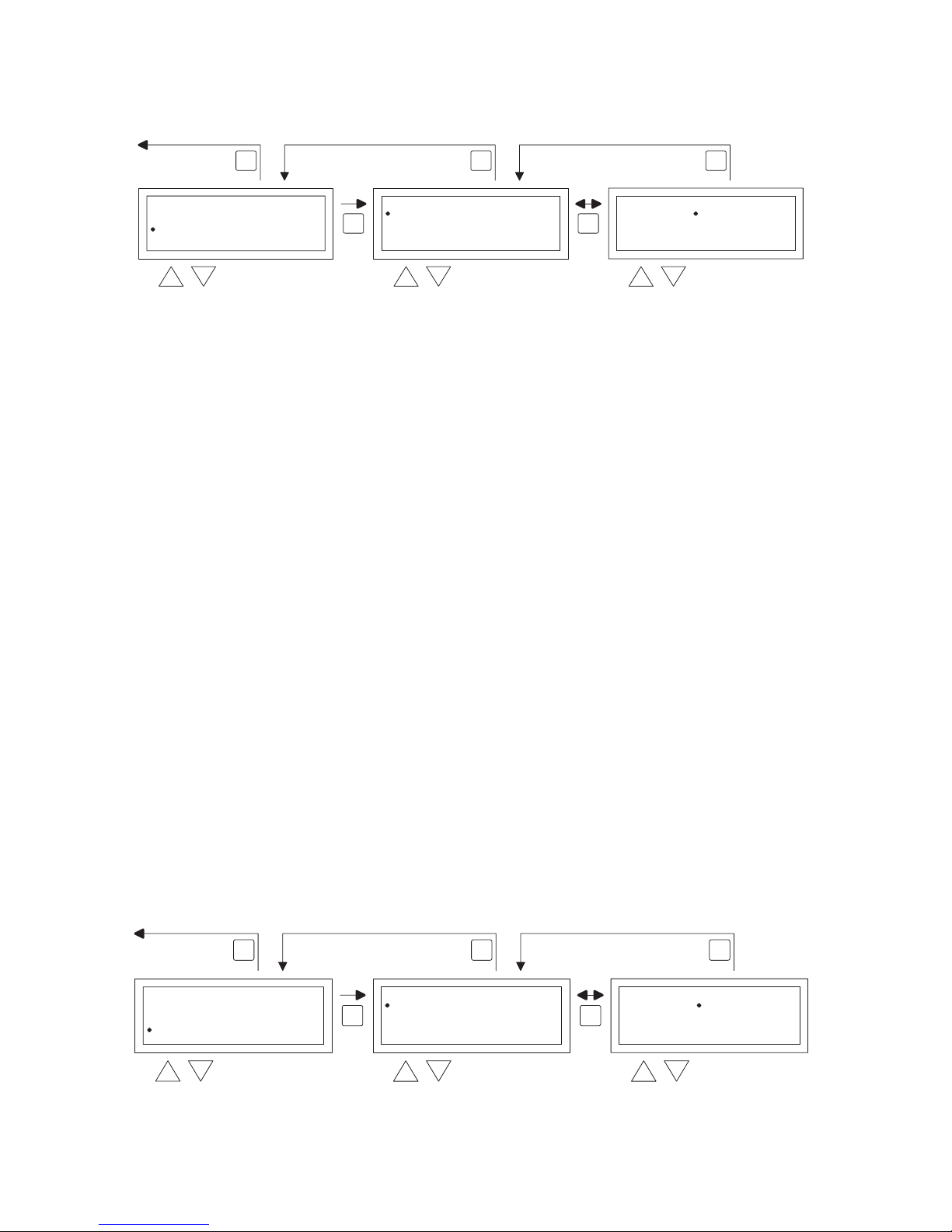
After you have connected the electricity supply the OptiTerm display will light up and ask you:
1. To select the correct language.
2. To enter the correct data and time.
For this, follow the image below:
•
Select with the and button, the desired language and conrm this with the OK button.
•
The display now automatically jumps to the date setting. Now change the day, month and year,
in that order with the and button. Conrm each entry with the OK button after which
the display automatically goes to the following entry. After you have changed the year, the display will automatically go to the time settings.
•
Now change the hours and minutes, in that order with the and button. Conrm each
entry with the OK button after which the display goes automatically to the following entry.
•
After the minutes are lled in the main screen will be shown on the display and the OptiTherm
is ready for use.
For further explanation see the sequence of this technical manual.
– For the operation and explanation of the display and the buttons, see §4.0 Operation.
– For changing the settings see §5.0.
– For the Messages and Malfunctions see §6.0.
7
EN
OK
modify
OK
OK
to next digit
Language
Nederlands
Deutsch
Français
English
English
Date/Time
Date
Time
--201101 03
08:00
5.0 °C
01-03-2011
08:30
0.21
modify
Page 8

4.0 Operation
4.1 Explanation of buttons
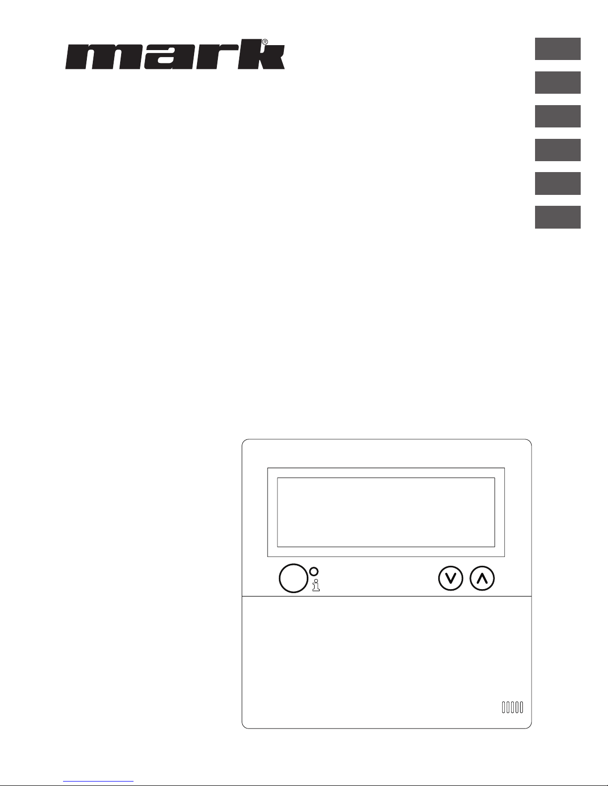
A - Display
B - Red led i
Lights up when there is a Malfunction Message.
C - Info push-button (blue)
With this the actual (Malfunction) Messages can be passed through from the air heaters.
D - Push-button for switching the heating mode on and off.
E - Push-button for switching the ventilator on and off.
F - Push-button for switching the overtime timer on and off.
Every push increases the time by 15 mins.
You switch the timer off again by keeping the push-button pressed in.
G - No function
H - ESC Push-button
Menu or item left without executing changes
I - RESET Push-button
Reset a Malfunction
J - OK Push-button
Conrm a choice or proceed in order to change the next gure.
K - (up) and (down) buttons
The menu proceeds if a setting is increased or decreased.
8
B
C
A
G
H
I
J
KF
E
D
12.0
08:00
01-03-2011
18.0 °C
RESETESC
OK
Page 9

4.2 Explanation of display and symbols.
Display
A - Shows the measured room temperature.
B - Displays the desired room temperature.
Displays the mode of operation (DAY, NIGHT, ECO, FROST PROTECTION)
C - Indicates which functional mode is switched on (HEATING, VENTILATION),
if there is a heating request and of the Message ⦻ (clip 1 and 2 on the air heater disconnected) is active.
D - Reason for the mode of operation.
(clock switch, overtime timer or exception day)
E - Shows the actual date and time
Symbols
F - Heating mode switched on symbol
G - Heating request symbol
H - Ventilator switched on symbol
I or II indicates if the ventilator is in high or low position (if applicable).
I - Message OFF (clip 1 and 2 on equipment disconnected)
J - Clock switch active symbol
K - overtime timer active symbol
(running time indicates when this function will be switched off again)
L - Exception day active symbol
M - Day temperature symbol (factory setting 18 °C)
N - Night temperature symbol (factory setting 15 °C)
O - Eco temperature symbol (factory setting 8 °C)
P - Frost protection symbol (factory setting 5 °C)
9
EN
B
C
A
D
E
06 29 191
OptiTherm
12.0
08:00
01-03-2011
18.0 °C
00:15
F
G
H
IP
O
N
M
K
L
01:00
J
Page 10
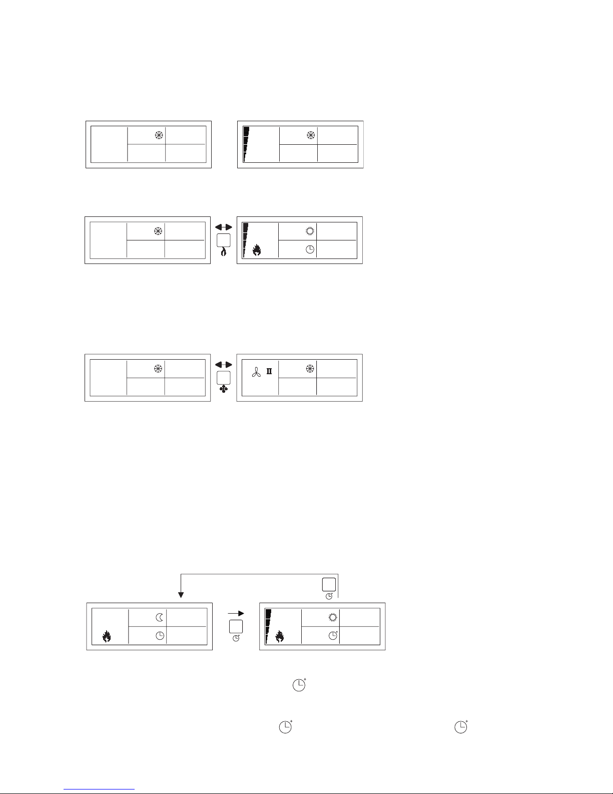
4.3 Frost protection
The OptiTherm is supplied with a frost protection function. This means that when the room
temperature falls below the set frost temperature, the air heater(s) are automatically switched on.
That is also the case when the heating mode is not switched on. The frost temperature is set as
standard at 5°C, you can change that, if you wish, for that see §5.2 change temperature setting.
4.4 Switch heating mode on/off.
To switch the heating mode on or off, you push the button “heating”.
The ame symbol will now appear on the display so that you can see that the heating mode is
switched on. With heating request, the status bar will also appear on the display.
4.5 Switch ventilation mode on/off.
To switch the ventilator of the air heater on or off, you push the button “ventilation”.
The ventilator symbol will now appear with I or II on the display so that you can see that the ventilator is switched on.
Note!
The ventilation mode can be used at the same time as the heating mode. So if you wish during
heating mode you can have the ventilator running continuously.
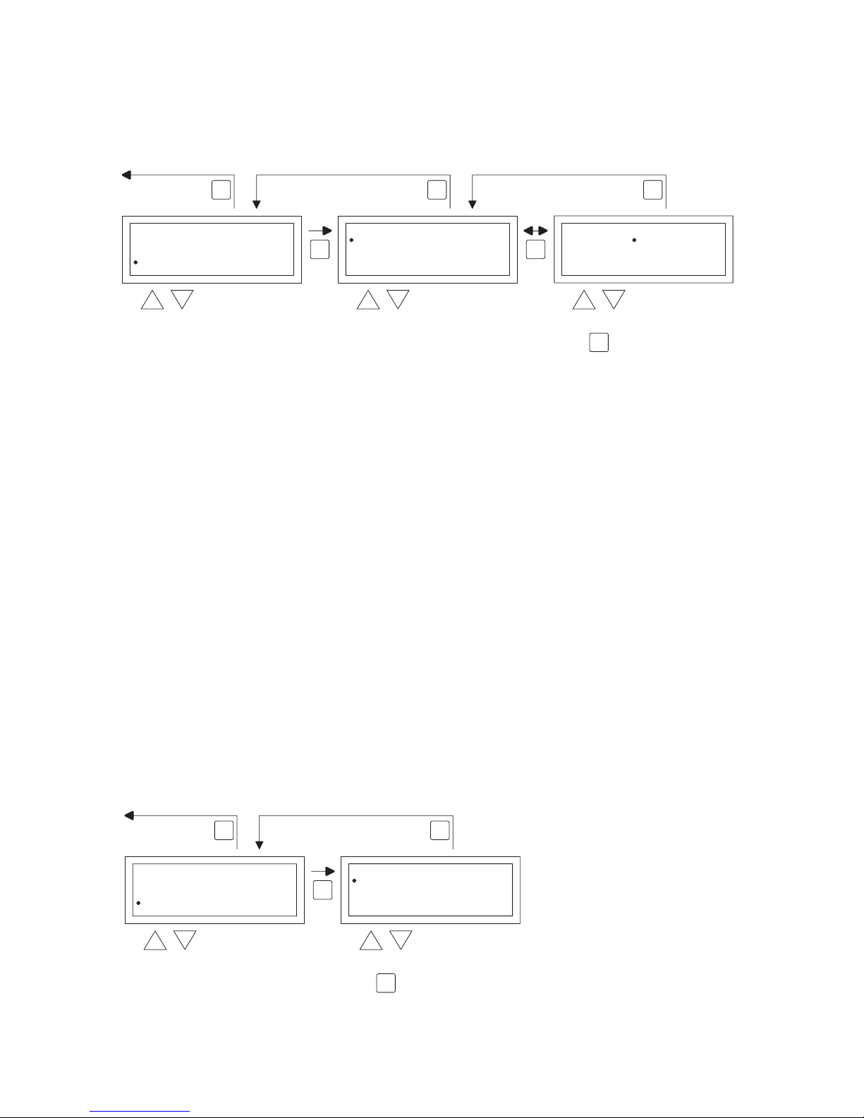
4.6 Switch overtime timer on/off
When you want to switch to another operation mode outside the program switch times you can
make use of the overtime timer
See the image below:
– Switch on overtime timer : press in button
or increase the time duration. Every time this button is pushed in, the time duration is in-
creased by 15 mins.
– Switch off overtime timer : keep button pushed in until the symbol and the time
remaining disappear from the screen
10
16.0
17:00
01-03-2011
18.0 °C
00:15
16.0
01-03-2011
15.0 °C
17:00
hold
± 3sec.
1x = 00:15
2x = 00:30
3x = 00:45
enz...
04.0
08:00
01-03-2011
05.0 °C05.0 °C
01-03-2011
08:00
0.90
12.0
17:00
01-03-2011
18.0 °C05.0 °C
01-03-2011
08:00
0.21
21.0
08:00
01-03-2011
05.0 °C05.0 °C
01-03-2011
08:00
0.21
Page 11

EN
11
As standard, the overtime timer will switch the OptiTherm to the day temperature The maximum time duration is 3:00 hrs. The settings can be changed in the settings menu: §5.7 overtime
timer
5.0 Change settings
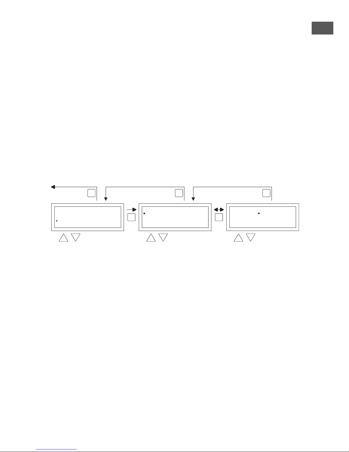
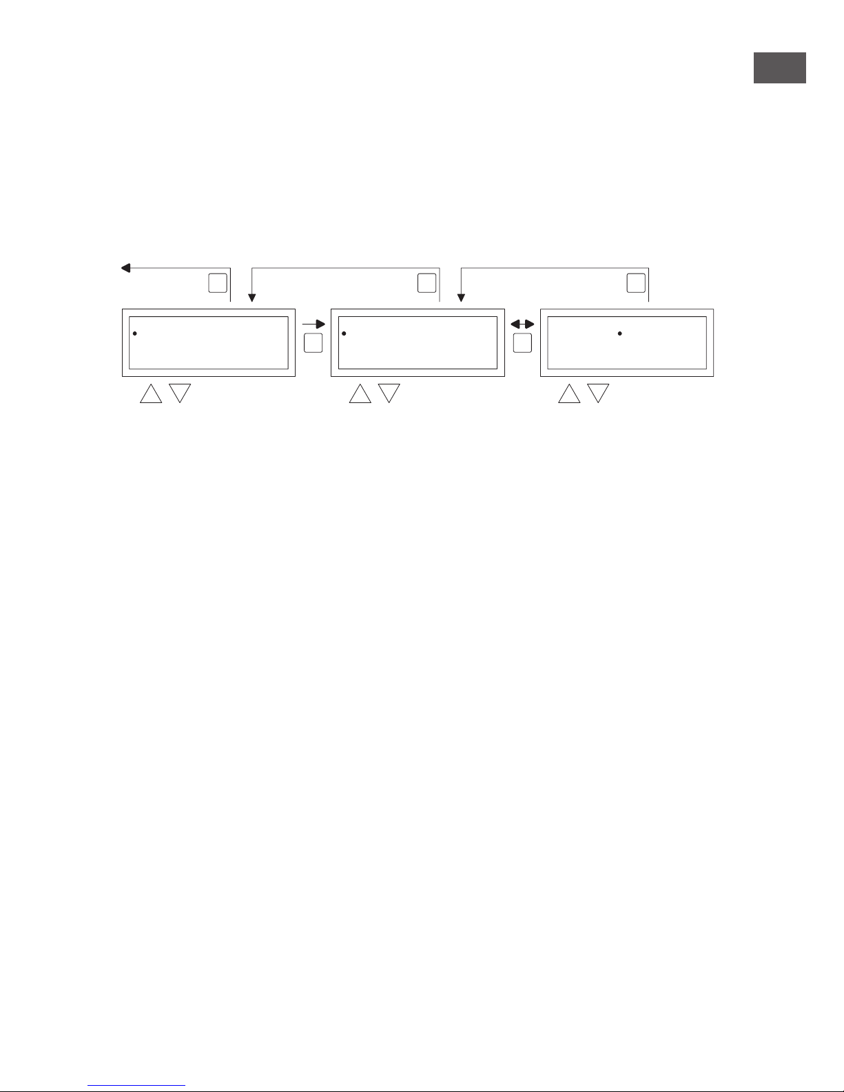
5.1 Call user menu
To activate the users menu:
•
You push the OK button.
•
After which you enter the correct Pin code according to the image below
(standard factory setting is 1000).
•
with the and button you change the ashing gure.
•
you conrm this with the OK button and you jump to the next gure. After you push on the
OK button at the 4th gure and you enter the correct pin code, you enter the user menu and
you can change the temperature setting, the switch times, the exception days and all the other
settings.
When an incorrect pin code is entered the screen image pin code input remains visible and the
code jumps back to 0000.
Note!
When no button is pressed for the duration of 1 minute the OptiTherm display will automatically
leave the menu and go back to the main display.
selectmodify
User Menu
Clock Program
Special day
Settings
Temperature
OK
ES
CE
SC
2x
OK
factory default
menu code
1 0 0 0
User Menu
18.0 °C
01-03-2011
08:10
0.21
Code 0000
OK
na 4x
to next digit
Page 12

12
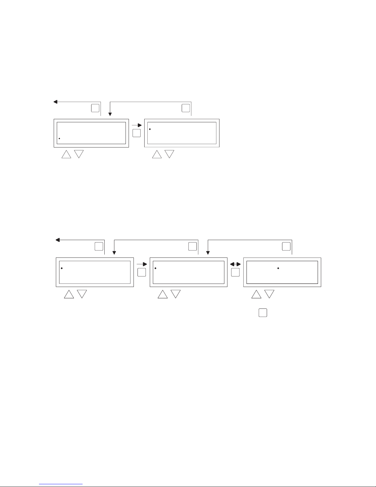
5.2 User menu: change the temperature setting
To change the temperature setting you follow the images below.
•
In the user menu select the menu-item temperature and then push the OK push-button.
•
With the and button, select the mode of operation which you wish to change and con-
rm this with the OK button.
•
The display jumps to the temperature setting of the chosen mode of operation. With
the and button, change the temperature setting and conrm this with the OK button.
Follow the steps above to change the other temperature settings.
When you are nished with changing the temperature settings:
•
After the last change you press the OK button to conrm this.
•
Then you push the ESC button to go back to the user menu again.
5.3 User menu: change/set the clock program
To adjust the existing clock program or to enter new times:
•
You select the menu item clock program and then you push the OK button.
•
Now change the existing clock program or input a new clock program following the images
below.
•
Now with the and button, you select the menu-item program and then push the OK but-
ton
•
With the and button, select a new or existing program block (1 to 20) and then push the
OK button.
•
Now with the and button, you select Day and then push the OK button
•
Now with the and button, you change to the desired days and then push the OK button
again.
(12345, 1234567, 1, 2, 3, 4, 5, 6, 7, 67, 2345 or off).
1=Monday, 2=Tuesday, 3=Wednesday, ……, 6=Saturday, 7=Sunday
•
Now with the and button, you select the switch time program and then push the OK
button
•
now with the and button you change the hours and minutes from the start and end times,
in that order. Conrm each entry with the OK button after which the display goes automati-
cally to the following entry. After you conrm the last entry you automatically go back to the
menu-item clock program
User Menu
Clock Program
Special day
Settings
Temperature
OK OK
ESC ESCESC
back to main screen
selec
tm
odify
Temperature
Eco
Night
Frost
Day
5.0 °C
8,0 °C
15,0 °C
18,0 °C
Temperature
Eco
Night
Frost
Day
5.0°C
8,0°C
15,0°C
18,0°C
select
Clock Program
Date
Interval
Switch to
Program
12345
08:00 >> 17:00
Day
1
Clock Program
Date
Interval
Switch to
Program
12345
08:00 >> 17:00
Day
1
OK OK
ES
CE
SCESC
select select modify
User Menu
Clock Program
Special day
Settings
Temperature
back to main screen
Page 13
EN
13
•
Now with the and button, you select switch to and then push the OK button.
•
Now with the and button you change the desired mode of operation (DAY, NIGHT,
ECO) and then push the OK button.
Repeat the above to input a new clock program or another change.
When you are nished with changing the clock program:
•
You push the ESC button to go back to the user menu again.
5.4 User menu: change/set exception day
Exception days can be used to allow the OptiTherm to switch to another mode of operation on
a certain date. After the exception day has passed then it automatically disappears from the program and it is again available for the entry of a new one. You have 20 program blocks available for
input.
To program or to change an exception day:
•
With the and button, you select the menu-item exception day and then push the OK
button
Now change the existing exception days or input new exception days following the images below.
•
With the and button, you select program and then push the OK button
•
Chose a new or existing program block (1 to 20). And conrm this with the OK button.
•
Now with the and button, select the desired date and conrm this with the OK button.
Change the date or enter a new date (day-month-year) by changing the day, month and year, in
that order with the and button. Conrm each entry with the OK button after which the
display goes automatically to the following entry. After you have changed the year, the display
will automatically go to the time settings.
•
Now with the and button select the switch time and with the and button change
the hours and minutes of the start and end time, in that order. Conrm each entry with the
OK button after which the display goes automatically to the following entry. After you conrm
the last entry you automatically go back to the menu-item Switch time
•
Now with and button select switch to and change the desired mode of operation in
DAY, NIGHT or ECO.
•
Conrm this by then pushing the OK button again
•
Repeat the above to enter a new exception day or to change an existing one.
•
Push the ESC button to go back to the main display.
OK OK
ESC ESCESC
select selec
tm
odify
Special day
Date
Interval
Switch to
Program
Off
___:___ >> ___:___
___
1
Special day
Date
Interval
Switch to
Program
Off
___:___ >> ___:___
___
1
back to main screen
User Menu
Clock Program
Special day
Settings
Temperature
Page 14
14
5.5 User menu: call settings menu
In the settings menu you can make more extensive setting changes such as, among other things,
the date/time, the maximum duration of the Overtime timer, the language and the pin code.
To enter the settings menu:
•
With the and button, you select the menu-item settings and then push the OK button
You are now in the menu settings and can now select various settings to change.
The setting which you can
change are:
- Date/Time
- Overtime timer
- Ventilator high/low
- Burner high/low
- Selection temperature sensor
- Calibrate thermostat
- Language
- Summer / winter time
- Info
- Pin code
- Service menu
5.6 Settings menu: Change date/time
To adjust the date/time you follow the images below.
•
With the and button, select the menu-item Date/time in the menu settings and then push
the OK button.
•
Now select the date by pushing the OK button.
•
Change the date with the and button and conrm each input with the OK button after
which the display automatically goes to the next entry. After you have changed the year, the
display will automatically go back to the Date.
•
Now with the and button, select Time
•
Now with the and button, select Time and then push the OK button. With the and
button change the hours and minutes and conrm each entry with the OK button, after which
the display automatically goes to the next entry. After you conrm the last entry you automati-
cally go back to the Time.
User Menu
Clock Program
Special day
Settings
Temperature
OK
ESCESC
selec
ts
elect
Settings
Overtime setting
Fan high/low
Burner high/low
Date/Time
Select Temperature sensor
back to main screen
OK OK
ES
CE
SCESC
selectselect modify
Settings
Overtime setting
Fan high/low
Burner high/low
Date/Time
Select Temperature sensor
2x
Date/Time
Time
Datem01-03 2011-
:08 00
Date/Time
Date
Time
--201101 03
08:00
OK
to next digit
back to main screen
Page 15

EN
15
•
When you have nished the changes and these are conrmed with the OK button, you push
the ESC button to go back to the settings menu.
•
Now select another item to change or to go back to the user menu by pushing the ESC but-
ton. Push the ESC button again to go back to the main display.
5.7 Settings menu: Change overtime timer settings
To change the overtime timer settings you follow the image below.
•
With the and button, select the menu-item Overtime timer in the menu settings and then
push the OK button.
•
Now the maximum time duration of the overtime timer and to which mode of operation the
OptiTherm must be switched, can be changed using the overtime timer.
•
s elect the maximum setting time and then push the OK button.
•
With the and button, change the maximum time (minimum increasing or decreasing is 15
minutes). And then push the OK button.
•
With the and button Switch to, to change the mode of operation, and then push the OK
button.
•
With the and button, change the mode of operation in DAY, NIGHT or ECO and con-
rm this by pushing the OK button.
•
When you have nished the changes and these are conrmed with the OK button, you push
the ESC button to go back to the settings menu.
•
Now select another item to change or to go back to the user menu by pushing the ESC but-
ton. Push the ESC button again to go back to the main display.
5.8 Settings menu: Ventilator high/low setting
When the ventilator of the air heater is in high/low operation, in this menu item you can set when
this can switch to low. So here, for every mode of operation, you can determine if the ventilator
must function in the high or low mode.
Note:
In the ventilation mode only this setting is determined, in heating mode, the setting burner high/
low is also determined.
OK OK
ESC ESCESC
select select modify
Settings
Overtime setting
Fan high/low
Burner high/low
Date/Time
Select Temperature sensor
2x
Overtime setting
Switch to
Max time setting
Day
Overtime setting
Switch to
Max time setting
Day
01 :00 01 :00
back to main screen
Page 16
16
All operation modes (DAY, NIGHT, ECO) are set standard at high, see the image below to
change this.
•
With the and button, select the Ventilator high/low in the settings menu and then push
the OK button.
•
with the and button select the desire mode of operation (DAY, NIGHT, ECO) that
you wish to change and then push the OK button.
•
With the and button, change the setting (high or low) and conrm this by pushing the
OK button.
•
push the ESC button to go back to the settings menu when you have nished the changes and
have conrmed this with the OK button.
•
Now select another item to change or to go back to the user menu by pushing the ESC but-
ton. Push the ESC button again to go back to the main display.
5.9 Settings menu: Burner high/low setting
This menu-item determines, with an air heater in high/low operation, when the burner may switch
to low or high while in heating mode. The ventilator will then automatically switch to the high or
low mode.
Note!
– During the start up the burner will always operate in high mode.
– The time that the burner may operate at low or high may be determined by the differential.
The ventilator setting high/low will also be determined in this way.
– When the differential is the same or higher than the set value, the burner will be switched to
low.
– When the differential falls 0.5K under the set value the burner switches back to high.
– The burner will not switch high or low when with Ventilator high/low the ventilator is set on
low in a mode of operation.
The image below shows how you can change that:
OK OK
ESC ESCESC
select selec
tm
odify
Settins
2x
Burner high / low
Differential
Burner
1.0 K
High
Burner high / low
1.0 K
High
Differential
Burner
Overtime setting
Fan high/low
Burner high/low
Date/Time
Select Temperature sensor
back to main screen
OK OK
ESC ESCESC
select selec
tm
odify
Settings
2x
Fan high / low
Eco
Night
Day
High
High
High
Fan high / low
Eco
Night
Day
High
High
High
Overtime setting
Fan high/low
Burner high/low
Date/Time
Select Temperature sensor
back to main screen
Page 17

EN
17
•
With the and button, select Burner high/low and then push the OK button.
•
To change the standard setting push the OK button again.
•
Now with the button setting, change from to automatic and then push the OK button.
•
Now with the and button, select the differential and then push the OK button.
•
With the and button, now change the differential setting and conrm this with the OK
button.
•
When you have nished with the changes you leave the menu item by pressing the ESC button
and you go back to the settings menu.
•
Now select another item to change or to go back to the user menu by pushing the ESC but-
ton. Push the ESC button again to go back to the main display.
5.10 Settings menu: Selection temperature sensor
With the OptiTherm you have the possibility to measure the room temperature by:
1. Thermostat: sensor built-in to OptiTherm itself
2. External zone: an external sensor connected to each air heater.
3. External average: an external sensor connected on one or more air heaters. Where the average
value is automatically calculated based on the number of connected sensors.
As standard, the temperature sensor on the OptiTherm is used.
When use is made of 1 or more external sensors, you must indicate this in the settings menu
Change selection temperature sensor.
See the image below:
To adjust this:
•
Select the menu-item Selection temperature sensor and then push the OK button.
•
Select the sensor by pushing the OK button.
•
Change the setting and then push the OK button.
You can choose from the thermostat (OptiTherm sensor), external zone (each air heater one
own external sensor) or external average (1 or more sensors).
•
When you have nished with the changes you leave the menu item by pressing the ESC button
and you go back to the settings menu.
•
Now select another item to change or to go back to the user menu by pushing the ESC but-
ton. Push the ESC button again to go back to the main display.
5.11 Settings menu: Calibrate thermostat/external sensor
When because of unfavourable circumstances there is a deviation in the displayed measured room
temperature and the actual room temperature, you can adjust this deviation by calibrating the
OptiTherm. Always ensure that the thermostat or external sensor is properly mounted and connected.
OK OK
ESC ESCESC
select select modify
Settings
Calibrate
2x
Select Temperature sensor
Sensor Room Control
Select Temperature sensor
Sensor Room ControlOvertime setting
Fan high/low
Burner high/low
Select Temperature sensor
back to main screen
Page 18
18
For example:
The measured temperature is 18°C, the screen display on the OptiTherm shows 20°C. The difference in this example is therefore 2°C too high the correction value must then be set at -2°C.
You can change this following the image below:
•
Now with the and button, select Calibrate Thermostat and then push the OK button
•
Only applicable when an external sensor is also used.
•
With the and button, select Sensor and then push the OK button
•
Only applicable when an external sensor is also used.
•
Now with the and button select the air heater (1 to 8) from where the external sensor
must be calibrated and then push the OK button.
•
With the and button, select Deviation and then push the OK button
•
With the and button set the desired value and conrm this with the OK button.
•
When you have nished with the changes you leave the menu item by pressing the ESC button
and you go back to the settings menu.
•
Now select another item to change or to go back to the user menu by pushing the ESC but-
ton. Push the ESC button again to go back to the main display.
5.12 Settings menu: Change language
If you want to change the chosen language you can change this by going to the settings menu and
changing the language.
To change the chosen language you follow the image below.
OK OK
ESC ESCESC
select select modify
Language
2x
OK
to next digit
Calibrate
Deviation
Sensor
0.0 K
Room Control
Calibrate
Deviation
Sensor
0.0 K
Room Control
back to main screen
Settings
Calibrate
Fan high/low
Burner high/low
Select Temperature sensor
OK
ESCESC
back to main screen
select select
Settings
Select Temperature sensor
Calibrate
Language
Fan high/low
Summer/wintertime
2x
Language
Nederlands
Deutsch
Français
English
English
OK
conrm selection
Page 19

EN
19
•
With the and button, select Language and then push the OK button
•
With the and button, select the desired language and conrm this with the OK button. In
the middle of the top of the screen the chosen language is shown and the display also appears in
that language.
•
When you have nished with the changes you leave the menu item by pressing the ESC button
and you go back to the settings menu.
•
Now select another item to change or to go back to the user menu by pushing the ESC but-
ton. Push the ESC button again to go back to the main display.
5.13 Settings menu: Switch on/off Summer / winter time
The OptiTherm has an automatic summer/wintertime conversion. When this is not desired, it can
be switched off here.
Follow the image below to change it.
•
In the settings menu select Summer/winter time and then push the OK button.
•
Select status by pushing the OK button
•
With the and button, change the setting on/off and conrm this with the OK button.
•
Quit summer/winter time by pushing the ESC button The display now goes back to the set-
tings menu.
•
Now select another item to change or go back to the user menu by pushing the ESC button.
Push the ESC button again to go back to the main display.
5.14 Settings menu: Info
In this menu-item you can read the software version and if applicable the measured value of the
external temperature sensor.
OK OK
ESC ESCESC
back to main screen
select selec
tm
odify
Setting
Calibrate
Language
Summer/wintertime
Select Temperature sensor
Information
2x
Summer/wintertime
State Automatic
Summer/wintertime
StateAutomatic
OK
ESCESC
select
Setting
Language
Summer/wintertime
Information
Calibrate
PIN
2x
Information
Software version 1.0 [xxxxxxxx]
Outside temperature __,_ °C
back to main screen
Page 20

20
•
In the settings menu select Info and then push the OK button. The info data is now shown on
the screen.
•
Quit Info by pushing the ESC button. The display now goes back to the settings menu.
•
Now select another item to change or go back to the user menu by pushing the ESC button.
Push the ESC button again to go back to the main display.
5.15 Settings menu: Change pin code
The OptiTherm is provisioned with a security pin code as standard. This is set as 1000. If desired,
you can change this to another Pin code.
Follow the image below to change the Pin code.
•
In the settings menu select Pin code and then push the OK button.
•
With the and button, change the rst gure and conrm this by pushing the OK button,
the display automatically jumps to the next gure. Change all desired gures in that way. After
the 4th gure the display automatically goes back to the settings menu.
•
Now select another item to change or go back to the user menu by pushing the ESC button.
Push the ESC button again to go back to the main display.
5.16 Settings menu: Call service menu
To call the service menu you follow the image below.
OK OK
ESCESC
back to main screen
select modify
Settings
Summer/wintertime
Information
PiIN
Language
Service menu
2x
PIN
Code
New PIN
0000
OK
to next digit
4x
OK OK
ESCESC
back to main screen
select select
Settings
Information
PIN
Service menu
Summer/wintertime
2x
Service menu
Code 0000 Control On/Off
Service menu
to next digit
OK
ESC
factory default
Service menu code
5 0 5 0
Page 21
EN
21
•
In the settings menu select Service menu and then push the OK button.
•
Now enter the Pin code for the service menu. With the and button, change the rst
gure and conrm this by pushing the OK button, the display automatically jumps to the next
gure. Change all desired gures in that way. After the 4th gure, when the pin code has been
correctly entered, the service menu is displayed on the screen.
In the service menu, you can change the Regulation on/off.
5.17 Service menu: Regulation on/off (switch differential).
Here, if desired you can change the switch differential per connected appliance.
Follow the image below to adjust it.
•
With the and button, select Regulation on/off in the service menu and then push the OK
button.
•
Now with the and button, select “Appliance” and then push the OK button again.
•
with the and button, select desired air heater (1 to 8) and conrm this with the OK but-
ton.
•
With the and button select Switch differential, to adjust this, and then push the OK but-
ton.
•
With the and button the switch differential can be changed between 0.5°C en 2.0°C and
conrm this with the OK button.
•
Then you can leave the Service menu by pressing the ESC button twice.
•
Push the ESC button again to go back to the settings menu.
•
Now select another item to change or to go back to the user menu by pushing the ESC but-
ton. Push the ESC button again to go back to the main display.
OK OK
ESCESC
back to main screen
select select
Service menu
Control On / Off
2x
Service menu
Unit
Service menu
modify
ESC
Switching differential 1.0 °C
1
Switching differential
Unit
1.0 °C
1
Page 22
22
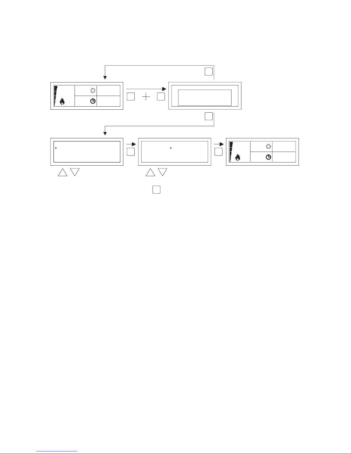
5.18 Recover factory settings
When you execute this function all settings in the OptiTherm are reset to the factory settings
§2.2. This function can be executed at any time.
Follow the image below to execute this function.
•
Keep pushing the ESC button and the OK button simultaneously for +/- 12 seconds until the
text ‘Factory Settings’ is displayed on the screen.
•
Only applicable when you wish to recover the factory settings
To execute, press the OK button. The factory values are recovered and the language, date and
time must be entered again. For this, also see §3.5 First Initial Operation
•
Only applicable when you do not wish to recover the factory settings
Press the ESC button to quit the function again.
The main display is shown again and the factory values are not reset.
OK
select
to next digit
OK
modify
Date/Time
Time
Date 01 -03 2011-
:08 00
18.0 °C
01-03-2011
09:00
0.51
Language
Nederlands
Deutsch
Français
English
English
18.0 °C
01-03-2011
09:00
0.51
ESC OK
Reset
RESTORE
FACTORY DEFAULT
OK-CONTINUE
ESC-BACK
ESC
OK
OK
±12sec.
Page 23

EN
23
6.0 Messages and Malfunctions
6.1 Message ⦻
When the Message ⦻ is shown in the display it means that one of the connected air heaters is
blocked. The cause of which is that the connection or external contact between the clips 1 and 2
is not present. By pressing the blue info button, it can be seen which of the connected air heaters
caused this Message.
When the contact or connection has been reset the Message will disappear and the air heater
concerned will function normally again.
6.2 Malfunction Messages
In the case of a Malfunction of the air heater the red light on the OptiTherm will light up. By
pushing the blue info button it can be seen which Malfunction and which air heater that concerns.
The ‘Error’ Message is also shown on the screen with a Malfunction code and the Message text
below. In the upper left of the screen you can see which air hater than concerns. By pressing the
blue info button once more the current Message of each air heater can be seen.
See the table below for the correct Malfunction Message. The Malfunction code indicates the nature of the Malfunction.
With the Reset button, the Malfunction can be rectied after which the Message will disappear
and the main screen is shown again on the display.
15.0
10:00
01-03-2011
18.0 °C
00:15
18.0 °C
HEATER
1
Operating
Hours15.0 °C
1 2 3 4 5 6L1 N PE
through reports
heater 1 t/m 8 then
back to main screen
Red LED is lit!
through reports
heater 1 t/m 8 then
back to main screen
Reset malfunctions
RESET
18.0 °C
LIVE AND NEUTRAL REVERSED
HEATER
1
Operating
Hours15.0 °C
Error :65
18.0 °C
01-03-2011
09:00
0.51
18.0 °C
01-03-2011
09:00
0.51
RESET
± 10sec.
Page 24

24
Fault code chart
Remarks!
Please refer also to the technical documentation for the air heater for information on the above
faults, causes and solutions.
7.0 Disposal of the OptiTherm.
When the OptiTherm is replaced or removed, it must be recycled or destroyed in accordance
with national and/or local legislation and regulations.
Code Meaning Cause
01 Ignition failure Ignition has failed (three attempts at ignition).
02 Gas valve relay/T max. Maximum thermostat is open
03 Gas valve
Gas valve faulty / Wire connecting the gas valve to the
burner control box is open-circuit or has been incorrectly connected.
22 Air compression switch The air compression switch is not open
23 Filters/system fan Filter is dirty/system fan has suffered a thermal failure
24 Air compression switc The air compression switch is not off
25 T max. Maximum thermostat is open
31 Too many attempts to restart Flame goes out (3x) when the device is in operation.
65 Phase and zero back to front Phase and zero not connected correctly
73 Ambient temperature sensor Ambient temperature sensor interrupted
76 System sensor System temperature sensor interrupted
81 Ambient temperature sensor Ambient temperature sensor has short circuited
84 System sensor System temperature sensor has short circuited
When a different error code displayed on the thermostat appears, press the Reset button in rst. If the
fault then come back, please contact the vendor of the device.
Page 25

EN
25
Page 26

26
Inhalt
Warnhinweise ..................................................................................................................................Seite 27
1.0 Allgemeines
1.1 Änderungen vorbehalten ................................................................................................Seite 27
1.2 Allgemeine Warnhinweise .............................................................................................. Seite 27
1.3 Art und Anwendung des Thermostaten ................................................................... Seite 27
2.0 Technische Daten
2.1 Technische Daten ............................................................................................................. Seite 28
2.2 Werkseinstellungen ..........................................................................................................Seite 29
3.0 Montage und Inbetriebnahme
3.1 Allgemeines ........................................................................................................................ Seite 29
3.2 Anbringung ........................................................................................................................ Seite 29
3.3 Verdrahtung ....................................................................................................................... Seite 30
3.4 Montage und Einbau ......................................................................................................... Seite 30
3.5 Erstmalige Inbetriebnahme ............................................................................................. Seite 31
4.0 Bedienung
4.1 Erläuterung der Tasten ....................................................................................................Seite 32
4.2 Erläuterung des Displays und der Symbole ................................................................Seite 33
4.3 Frostüberwachung ............................................................................................................ Seite 34
4.4 Die Stellung Heizen ein-/ausschalten............................................................................Seite 34
4.5 Die Stellung Lüften ein-/ausschalten ............................................................................. Seite 34
4.6 Überstundentimer ein-/ausschalten .............................................................................. Seite 34
5.0 Einstellungen ändern
5.1 Benutzermenü aufrufen ................................................................................................... Seite 35
5.2 Benutzermenü: Temperatureinstellung ändern .........................................................Seite 36
5.3 Benutzermenü: Zeitschaltprogramm einstellen/ändern ........................................... Seite 36
5.4 Benutzermenü: Ausnahmetag einstellen/ändern........................................................Seite 37
5.5 Benutzermenü: Menü Einstellungen aufrufen ............................................................. Seite 38
5.6 Menü Einstellungen: Datum/Uhrzeit ändern ..............................................................Seite 38
5.7 Menü Einstellungen: Einstellungen Überstundentimer ändern .............................. Seite 39
5.8 Menü Einstellungen: Lüfter hoch/niedrig ..................................................................... Seite 39
5.9 Menü Einstellungen: Brenner hoch/niedrig ................................................................. Seite 40
5.10 Menü Einstellungen: Auswahl Temperatursensor ..................................................... Seite 41
5.11 Menü Einstellungen: Kalibrierung Thermostat/externer Sensor .......................... Seite 42
5.12 Menü Einstellungen: Sprachauswahl ändern ...............................................................Seite 43
5.13 Menü Einstellungen: Sommer-/Winterzeit ein-/ausschalten ...................................Seite 43
5.14 Menü Einstellungen: Info ................................................................................................. Seite 44
5.15 Menü Einstellungen: Geheimzahl ändern .....................................................................Seite 44
5.16 Menü Einstellungen: Servicemenü aufrufen .................................................................Seite 45
5.17 Servicemenü: Regelung ein/aus ändern (Schaltdifferenz) .........................................Seite 45
5.18 Auf Werkseinstellungen zurücksetzen ........................................................................Seite 46
6.0 Meldungen und Störungen
6.1 Meldung .............................................................................................................................Seite 47
6.2 Störungsmeldungen .......................................................................................................... Seite 47
7.0 Entsorgen des OptiTherm-Gerätes .............................................................................. Seite 48
Abbildungen/Tabellen
[1] Tabelle Kabeldurchmesser und max. Länge Verdrahtung ....................................... Seite 99
[2] Übersicht Anschluss des Thermostaten ....................................................................Seite 99
[3] Anschluss des OptiTherm an einen oder mehrere Lufterhitzer ........................... Seite 100
[4] Richtige Adressierung des OptiTherm ........................................................................ Seite101
[5] Einstellen der Dipschalter und Schalter S4 Lufterhitzer ..........................................Seite102
Schnellstart .......................................................................................................................................... Seite 103
Page 27

27
DE
Lesen Sie dieses Dokument sorgfältig
durch, bevor Sie das Gerät installieren
Warnhinweis
Fehlerhaft durchgeführte Installationen, Einstellungen, Änderungen, Reparaturen oder Wartungsmaßnahmen können zu Sachschäden und Verletzungen führen. Alle Arbeiten müssen von
geprüften, qualizierten Fachleuten durchgeführt werden. Falls das Gerät nicht vorschriftsgemäß montiert wird, erlischt die Garantie. Dieses Gerät ist nicht für den Gebrauch durch
Personen (einschließlich Kindern) mit verminderter körperlicher, Sinnes- oder geistiger Leistungsfähigkeit oder mangelnder Erfahrung und mangelnden Kenntnissen bestimmt, sofern sie
nicht unter Aufsicht stehen oder durch eine Person, die für ihre Sicherheit verantwortlich ist,
im Gebrauch des Geräts angeleitet werden. Kinder müssen beaufsichtigt werden, um zu verhindern, dass sie das Gerät als Spielzeug benutzen.
Wenn in der technischen Anleitung auf eine Abbildung oder Tabelle verwiesen wird, wird
eine Zahl in eckigen Klammern angegeben, beispielsweise [3]. Die Zahl verweist auf die
Abbildungen und Tabellen mit der entsprechenden Nummer am Ende dieser technischen
Anleitung.
1.0 Allgemeines.
1.1 Änderungen vorbehalten.
Der Hersteller strebt eine kontinuierliche Verbesserung der Produkte an und behält sich das
Recht vor, ohne vorherige Mitteilung Änderungen an den technischen Daten vorzunehmen. Die
technischen Angaben werden als korrekt angenommen, bilden aber keine Grundlage für einen
Vertrag oder Gewährleistungsansprüche. Alle Bestellungen werden gemäß den Standardkonditionen in unseren allgemeinen Verkaufs- und Lieferbedingungen angenommen (diese werden auf
Anfrage zur Verfügung gestellt).
1.2 Allgemeine Warnhinweise.
Die Installation muss den geltenden landesweiten und örtlichen Bestimmungen entsprechen.
Daher darf die OptiTherm nur von einem sachkundigen und qualizierten Installateur unter
Beachtung der nationalen und internationalen Vorschriften installiert werden. Im Falle einer unsachgemäßen Installation, Einstellung, Änderung, Wartung oder Instandsetzung erlischt die Gewährleistung.
1.3 Art und Anwendung des Thermostaten.
Die OptiTherm ist ein digitaler Zeitschaltthermostat mit internem Raumfühler, der über ein Bussystem einen oder mehrere Lufterhitzer (Typ G(N)SD oder G(N)CD), jedoch höchstens acht, auf
der Grundlage der Raumtemperatur steuern kann.
Die OptiTherm ist ausgestattet mit:
•
Einer Funktion zum Ein- und Ausschalten der Stellung Heizen.
•
Einer Funktion zum Ein- und Ausschalten des Lüfters des Lufterhitzers/der Lufterhitzer.
•
Einer Funktion zum Melden und ggf. Aufheben von Störungen.
•
Einer Jahresuhr mit 20 Programmblöcken
Page 28

•
Einer Funktion zum Programmieren von Ausnahmetagen nach Datum.
•
Einer Funktion zum Programmieren von vier verschiedenen Betriebsarten (TAG, ÖKO,
NACHT, FROST).
•
Einem Überstundentimer, um außerhalb der Schaltzeiten in eine andere Betriebsart wechseln zu
können.
•
Einer Geheimzahlsicherung für die Einstellungen wie z. B. die Temperatur des Zeitschaltpro-
grammes usw.
•
Einem Frostwächter, der die Lufterhitzer automatisch einschaltet, wenn die Temperatur zu
stark absinkt.
2.0 Technische Daten.
2.1 Technische Daten.
•
Typbezeichnung : OptiTherm
•
Art des Thermostaten : Digitaler Zeitschaltthermostat
•
Artikelnummer : 06 29 191
•
Anschluss : Bussystem (2-Draht)
•
Verdrahtung : Geschirmtes Buskabel, siehe auch Punkt 3.3
•
Schaltdifferenz : 1 K
•
Abmessungen : 129 x 129 x 20mm (L x B x H)
•
Gewicht : 188 g
•
Schutzgrad : IP 30
•
Umgebungstemperatur : 0-40 °C
•
Temperatureinstellung : 0 bis 40 °C, in Schritten von 0,5 °C einstellbar
•
Zeitschaltprogramm : 20 Programmblöcke
Mo-Fr, Di-Fr, Sa-So, täglich oder pro Tag
•
Ausnahmetage : 20 Programmblöcke
Umschalten auf Tag-, Öko-oder Nachttemperatur
•
Überstundentimer : Nach Wahl einstellbar zwischen 15 Minuten und 24 Stunden
Umschalten auf Tag-, Öko- oder Nachttemperatur
•
Kalibrierung des Temperatursensors : einstellbar von -3,0 °C bis 3,0 °C
•
Raumfühler : standardmäßig vorhanden
•
Externer Sensor : Möglichkeit, pro Gerät oder auf der Grundlage einer
Durchschnittswertmessung die Temperatur zu messen.
•
Zeitanzeige : 24 Stunden
•
Sommer-/Winterzeit : Einstellbar auto/aus
•
Sprachen : Niederländisch, Englisch, Deutsch,
Französisch, Polnisch, Rumänisch
28
Page 29

DE
2.2 Werkseinstellungen.
•
Temperatur : Tag 18 °C
Öko 15 °C
Nacht 08 °C
Frost 05 °C
•
Zeitschaltprogramm : Programmblock 1
Tag 12345
Schaltzeit 08:00 >> 17:00
Umschalten auf Tagtemperatur
•
Ausnahmetag : aus
•
Überstundentimer : Maximale Zeiteinstellung 03:00 Stunden
Umschalten auf Tagtemperatur
•
Lüfter hoch/niedrig : Tag hoch
Öko hoch
Nacht hoch
•
Brenner hoch/niedrig : Brenner hoch
Differenz 1,0 K
•
Auswahl Temperatursensor : Sensor Thermostat
•
Kalibrierung des Temperatursensors : 0,0 °C
•
Sommer-/Winterzeit : Automatisch
•
Geheimzahl : 1 0 0 0
3.0 Montage und Inbetriebnahme
3.1 Allgemeines.
•
Prüfen Sie nach dem Entpacken der OptiTherm und - falls mitbestellt - des/der mitgelieferten
externen Sensoren diese auf Beschädigungen.
•
Prüfen Sie auch, ob der richtige Typ/das richtige Modell geliefert wurde (Thermostat: OptiT-
herm 0629191, externer Sensor: Digitaler Sensor für 2-Draht 0629194).
Wenden Sie sich an Ihren Händler, wenn der Thermostat beschädigt ist oder wenn Typ / Modell
nicht richtig sind.
3.2 Anbringung
Bei der Festlegung des geeigneten Anbringungsortes für die OptiTherm müssen die nachfolgenden
Punkte berücksichtigt werden:
– Installieren Sie die OptiTherm in dem zu heizenden Raum, da dieser mit einem internen Raum-
fühler ausgestattet ist. Dies gilt nicht, wenn ein externer Raumfühler (als Zubehör lieferbar) an
den/die Lufterhitzer angeschlossen wird.
– Montieren Sie die OptiTherm an einem zugfreien Ort.
– Montieren Sie die OptiTherm nicht an einer kalten Mauer/Wand.
– Montieren Sie die OptiTherm nicht unmittelbar im Luftstrom des/der Lufterhitzer(s).
– Es wird empfohlen, die OptiTherm ± 1,5 m über dem Fußboden anzubringen.
29
Page 30

30
3.3 Verkabelung
Zur Verkabelung ist immer ein geschirmtes Buskabel zu verwenden.
Maximale Länge und richtigen Durchmesser siehe in Tabelle [2].
Achtung!!!
Die Schirmung des Kabels am Lufterhitzer erden.
Das Buskabel muss gemäß der jeweils landesspezischen Ausführung gewählt werden, wobei die in
den technischen Daten genannten Werte beachtet werden müssen.
3.4 Montage und Einbau.
Zur korrekten Montage und beim Anschließen der OptiTherm am/an den Lufterhitzer(n) müssen
die nachfolgenden Punkte berücksichtigt werden:
•
Überprüfen Sie, ob die Stromversorgung getrennt ist. Wenn dies nicht der Fall ist, muss vor
weiteren Maßnahmen erst der Strom abgeschaltet werden. Lesen Sie hierzu auch die technische
Anleitung für den anzuschließenden Lufterhitzer.
•
Bringen Sie die OptiTherm an der Wand an und beachten Sie dabei Punkt 3.2, Montage der
OptiTherm.
•
Gilt nur, wenn externe Sensoren verwendet werden.
Installieren Sie den/die externen Sensor(en) am richtigen Ort. Lesen Sie hierzu auch die mit
dem Sensor mitgelieferte Anleitung.
•
Verlegen Sie die richtige Verkabelung zwischen dem Lufterhitzer und der OptiTherm bzw. zwi-
schen den einzelnen Lufterhitzern. Beachten Sie hierbei auch Punkt 3.3 Verkabelung [2][3]
•
Gilt nur, wenn externe Sensoren verwendet werden.
Verlegen Sie die richtige Verkabelung zwischen dem Lufterhitzer und dem externen Sensor.
Beachten Sie hierbei auch Punkt 3.3 Verkabelung und die Anleitung für den externen Sensor.
[2][4]
•
Schließen Sie die OptiTherm und den/die Lufterhitzer gemäß Schema an. [2] [3]
•
Gilt nur, wenn externe Sensoren verwendet werden.
Schließen Sie die Verkabelung korrekt am externen Sensor und Lufterhitzer an und beachten
Sie dabei auch die Anleitung für den externen Sensor. [2] [4]
•
Gilt nur für den Anschluss mehrerer Geräte an die OptiTherm.
Stellen Sie hierzu den Dipschalter und Schalter S4 am Brennerautomaten des Lufterhitzers korrekt ein. Achten Sie dabei darauf, dass der Lufterhitzer, an den die OptiTherm angeschlossen
Kabeltyp Einsatzbereich EIB-Spezikation
YCYM Feste Installation Trockene, Feucht- und Nassräume
Im Freien (keine direkte Sonneneinstrahlung)
Aufbau, Einbau, in Leitungen
J-Y(st)Y Feste Installation nur in Innenräumen
Aufbau, in Leitungen
JH(st)H Halogenfreie Leitungen,
Installation auf Abstand
A-2Y(L)2Y
A-2YF(L)2Y
Telefon-Erdkabel,
Installation im Außenbereich
Page 31

31
wird, stets als Gerät 1 adressiert wird. [5][6]
•
Sobald Installation und Anschluss abgeschlossen sind, können OptiTherm und Lufterhitzer in
Betrieb genommen werden. Lesen Sie hierzu auch die technische Anleitung für den Lufterhitzer.
3.5 Erstmalige Inbetriebnahme.
•
Stellen Sie die Stromversorgung wieder her, nachdem Montage und Installation von OptiTherm
und Lufterhitzern abgeschlossen sind. Lesen Sie hierzu auch die technische Anleitung für die
Lufterhitzer.
Nachdem die Stromversorgung hergestellt ist, leuchtet die Anzeige der OptiTherm, und es erscheinen die folgenden Aufforderungen:
1. Wählen Sie die richtige Sprache.
2. Geben Sie das richtige Datum und die richtige Zeit ein.
Beachten Sie dabei die nachfolgende Abbildung.
OK
Änderung
OK
OK
zum nächsten Titel
Language
Nederlands
Deutsch
Français
English
English
Datum/Zeit
Datum
Zeit
--201101 03
08:00
5.0 °C
01-03-2011
08:30
0.21
Änderung
•
Wählen Sie mit Taste und die gewünschte Sprache und bestätigen Sie mit der Taste OK.
•
Das Display wechselt jetzt automatisch zur Datumseinstellung. Ändern Sie jetzt der Reihe nach
Tag, Monat und Jahr mit Taste und . Bestätigen Sie jede Eingabe mit der Taste OK, woraufhin das Display automatisch zur nächsten Eingabe wechselt. Nachdem Sie das Jahr geändert
haben, wechselt das Display automatisch zur Einstellung der Uhrzeit.
•
Ändern Sie jetzt der Reihe nach Stunde und Minuten mit Taste und . Bestätigen Sie jede
Eingabe mit der Taste OK, woraufhin das Display automatisch zur nächsten Eingabe wechselt.
•
Nachdem die Minuten eingegeben wurden, erscheint der Hauptbildschirm auf dem Display und
die OptiTherm ist betriebsbereit.
Für weitere Erläuterungen siehe die weiteren Abschnitte dieser technischen Anleitung:
– Für Bedienung und Erläuterung des Displays und der Tasten siehe Bedienung Punkt 4.0.
– Für die Änderung der Einstellungen siehe Punkt 5.0.
– Für Meldungen und Störungen siehe Punkt 6.0.
DE
Page 32

32
4.0 Bedienung.
B
C
A
G
H
I
J
KF
E
D
12.0
08:00
01-03-2011
18.0 °C
RESETESC
OK
4.1 Erklärung der Tasten.
A - Display
B - Rote LED i
Leuchtet bei einer Störung.
C - Infotaste (blau)
Hiermit kann in der aktuellen (Störungs-)Meldung des Lufterhitzers geblättert werden.
D - Taste zum Ein- und Ausschalten der Stellung Heizen.
E - Taste zum Ein- und Ausschalten des Lüfters.
F - Taste zum Ein- und Ausschalten des Überstundentimers.
Mit jeder Betätigung der Taste wird die Zeit um 15 Minuten erhöht.
Durch Gedrückthalten der Taste wird der Zähler wieder ausgeschaltet.
G - Keine Funktion.
H - Taste ESC
Das Menü oder den Menüpunkt verlassen, ohne Änderungen durchzuführen.
I - Taste RESET
Zurücksetzen einer Störung.
J - Taste OK
Auswahl bestätigen oder zum nächsten Punkt gehen, um eine Änderung durchzuführen.
K - Tasten (up) und (down)
Das Menü durchlaufen oder eine Einstellung erhöhen oder verringern.
Page 33

33
4.2 Erläuterung des Displays und der Symbole.
B
C
A
D
E
06 29 191
OptiTherm
12.0
08:00
01-03-2011
18.0 °C
00:15
F
G
H
IP
O
N
M
K
L
01:00
J
Display
A - Zeigt die gemessene Raumtemperatur an.
B - Zeigt die gewünschte Raumtemperatur an.
Zeigt die Betriebsart an (TAG, NACHT, ÖKO, FROSTÜBERWACHUNG).
C - Zeigt an, welche Funktion eingeschaltet ist (HEIZEN, LÜFTEN), ob eine Wärmeanfor-
derung vorliegt und ob die ⦻ Meldung (Klemme 1 und 2 auf dem Lufterhitzer unterbrochen) aktiv ist.
D - Grund für die Betriebsart.
(Schaltuhr, Überstundentimer oder Ausnahmetag)
E - Zeigt die aktuelle Zeit und das aktuelle Datum an.
Symbole
F - Symbol Stellung Heizen eingeschaltet.
G - Symbol Wärmeanforderung
H - Symbol Lüfter eingeschaltet
I oder II zeigt Lüfter in hoher oder niedriger Stellung (falls zutreffend).
I - Meldung OFF (Klemme 1 und 2 am Gerät unterbrochen)
J - Symbol Schaltuhr eingeschaltet
K - Symbol Überstundentimer eingeschaltet
(ablaufende Zeit zeigt an, wann diese Funktion wieder ausgeschaltet wird)
L - Symbol Ausnahmetag aktiv.
M - Symbol Tagestemperatur (Werkseinstellung 18 °C)
N - Symbol Nachttemperatur (Werkseinstellung 15 °C)
O - Symbol Ökotemperatur (Werkseinstellung 8 °C)
P - Symbol Frostüberwachung (Werkseinstellung 5 °C)
DE
Page 34

34
4.3 Frostüberwachung.
Die OptiTherm ist standardmäßig mit einer Frostüberwachungsfunktion ausgestattet. Das bedeutet, dass der/die Lufterhitzer automatisch eingeschaltet wird/werden, wenn die Raumtemperatur
unter die eingestellte Frosttemperatur sinkt. Dies gilt auch, wenn die Stellung Heizen nicht eingeschaltet ist. Standardmäßig ist die Temperatur auf 5 °C eingestellt. Sie können dies, falls gewünscht, ändern. Siehe hierzu Punkt 5.2 Temperatureinstellung ändern.
04.0
08:00
01-03-2011
05.0 °C05.0 °C
01-03-2011
08:00
0.90
4.4 Die Stellung Heizen ein-/ausschalten.
Um die Stellung Heizen ein- oder auszuschalten, drücken Sie die Taste „Heizen“.
12.0
17:00
01-03-2011
18.0 °C05.0 °C
01-03-2011
08:00
0.21
Auf dem Display erscheint jetzt das Flammensymbol, das anzeigt, dass die Stellung Heizen eingeschaltet ist. Bei Wärmeanforderung erscheint auch die Statuszeile auf dem Display.
4.5 Die Stellung Lüften ein-/ausschalten.
Um den Lüfter des Lufterhitzers ein- oder auszuschalten, drücken Sie die Taste Lüften.
21.0
08:00
01-03-2011
05.0 °C05.0 °C
01-03-2011
08:00
0.21
Auf dem Display erscheint jetzt das Ventilatorsymbol mit einem „I’’ oder „II“, das anzeigt, dass der
Lüfter eingeschaltet ist.
Hinweis:
Die Stellung Lüften kann gleichzeitig mit der Stellung Heizen verwendet werden. Sie können also,
falls gewünscht, bei eingeschalteter Stellung Heizen den Lüfter ständig laufen lassen.
4.6 Überstundentimer ein-/ausschalten
Wenn Sie ungeachtet der programmierten Schaltzeit(en) in einen anderen Betriebszustand wechseln möchten, können Sie den Überstundentimer verwenden.
Siehe nachfolgende Abbildung:
16.0
17:00
01-03-2011
18.0 °C
00:15
16.0
01-03-2011
15.0 °C
17:00
halten
± 3sec.
1x = 00:15
2x = 00:30
3x = 00:45
usw...
– Überstundentimer einschalten : Taste drücken
oder die Dauer erhöhen Mit jeder Betätigung der Taste wird die Dauer um 15
Minuten erhöht.
– Überstundentimer ausschalten : Taste gedrückt halten, bis das Symbol und die
ablaufende Zeit aus dem Display verschwinden.
Page 35

35
Standardmäßig schaltet der Überstundentimer die OptiTherm auf die Tagestemperatur um. Die
maximale Dauer beträgt 03:00 Stunden. Diese Einstellungen können im Menü Einstellungen geändert werden: Überstundentimer Punkt 5.7.
5.0 Einstellungen ändern.
5.1 Benutzermenü aufrufen.
Um das Benutzermenü aufzurufen:
•
Drücken Sie die Taste OK.
•
Anschließend geben Sie gemäß nachfolgender Abbildung die richtige Geheimzahl ein
(die Standard-Werkseinstellung ist 1000).
AuswahlÄnderung
Benutzermenu
Zeit Programm
Sondertage
Einstellungen
Temperatur
OK
ES
CE
SC
2x
OK
zur nächsten Ziffer
Werkeinstellung
menu code
1 0 0 0
Benutzermenu
18.0 °C
01-03-2011
08:10
0.21
Code 0000
OK
nach 4x
•
mit Taste und ändern Sie die blinkende Zahl
•
mit der Taste OK bestätigen Sie dies und wechseln Sie zur nächsten Zahl. Nachdem Sie bei der
4. Zahl die Taste OK gedrückt und die Geheimzahl korrekt eingegeben haben, können Sie die
Temperatureinstellung, die Schaltzeiten, die Ausnahmetage und alle anderen Einstellungen ändern.
Wenn eine falsche Geheimzahl eingegeben wurde, wird der Bildschirm mit der Geheimzahleingabe
weiterhin angezeigt und wechselt die Geheimzahl wieder zu 0000.
Hinweis:
Wenn während 1 Minute keine Taste gedrückt wird, verlässt die OptiTherm automatisch das
Menü und kehrt zum Hauptbildschirm zurück.
DE
Page 36

36
5.2 Benutzermenü: Temperatureinstellung ändern.
Um die Temperatureinstellungen zu ändern, gehen Sie gemäß nachfolgender Abbildung vor:
Benutzermenu
Zeit Programm
Sondertage
Einstellungen
Temperatur
OK OK
ESC ESCESC
zurück zum Hauptbildschirm
Auswahl Auswahl
Temperatur
Eco
Nacht
Frost
Tag
5.0 °C
8,0 °C
15,0 °C
18,0 °C
Temperatur
Eco
Nacht
Frost
Tag
5.0°C
8,0°C
15,0°C
18,0°C
Auswahl
•
Wählen Sie im Benutzermenü den Menüpunkt Temperatur und drücken Sie dann die Taste OK.
•
Wählen Sie mit Taste und die Betriebsart, die Sie ändern möchten, und bestätigen Sie dies
mit der Taste OK.
•
Das Display wechselt jetzt zur Temperatureinstellung der gewählten Betriebsart. Ändern Sie
mit Taste und die Temperatureinstellung und bestätigen Sie dies mit der Taste OK.
Führen Sie die oben genannten Schritte durch, um auch die anderen Temperatureinstellungen zu
ändern.
Wenn Sie die Temperatureinstellungen geändert haben:
•
Drücken Sie nach der letzten Änderung zur Bestätigung die Taste OK.
•
Dann drücken Sie die Taste ESC, um zum Benutzermenü zurückzukehren.
5.3 Benutzermenü: Zeitschaltprogramm einstellen/ändern.
Um das aktuelle Zeitschaltprogramm anzupassen oder um neue Zeiten einzugeben:
•
Wählen Sie den Menüpunkt Zeitschaltprogramm und drücken Sie dann die Taste OK.
•
Ändern Sie nun das aktuelle Zeitschaltprogramm oder geben Sie ein neues Zeitschaltprogramm
gemäß nachfolgender Abbildung ein.
Benutzermenu
Zeit Programm
Sondertage
Einstellungen
Temperatur
Zeit Programm
Tag
Schaltzeit
Schalten nach
Programm
12345
08:00 >> 17:00
Dag
1
Zeit Programm
Tag
Schaltzeit
Schalten nach
Programm
12345
08:00 >> 17:00
Dag
1
OK OK
ES
CE
SCESC
zurück zum Hauptbildschirm
AuswahlAuswah
lA
uswahl
•
Wählen Sie nun mit Taste und den Menüpunkt Programm und drücken Sie dann die Taste
OK.
•
Wählen Sie mit Taste und einen neuen oder vorhandenen Programmblock (1 - 20) und
drücken Sie dann die Taste OK.
•
Wählen Sie mit Taste und den Tag und drücken Sie dann die Taste OK.
•
Ändern Sie jetzt mit Taste und die gewünschten Tage und drücken Sie wieder die Taste
OK.
(12345, 1234567, 1, 2, 3, 4, 5, 6, 7, 67, 2345 oder aus).
1=Montag, 2=Dienstag, 3=Mittwoch, ……, 6=Samstag, 7=Sonntag
•
Wählen Sie nun mit Taste und die Schaltzeit und drücken Sie dann die Taste OK.
•
Ändern Sie jetzt mit Taste und der Reihe nach die Stunden und Minuten der Anfangs- und
Endzeit. Bestätigen Sie jede Eingabe mit der Taste OK, woraufhin das Display automatisch zur
nächsten Eingabe wechselt. Nach der letzten Eingabe kehren Sie automatisch zum Menüpunkt
Zeitschaltprogramm zurück.
Page 37

37
•
Wählen Sie mit Taste und „Wechseln zu“ und drücken Sie dann die Taste OK.
•
Ändern Sie jetzt mit Taste und die gewünschte Betriebsart (TAG, NACHT, ECO) und
drücken Sie dann die Taste OK.
Wiederholen Sie dies, um ein neues Zeitschaltprogramm einzugeben oder um eine weiteres zu
ändern.
Wenn Sie das Zeitschaltprogramm geändert haben:
•
Drücken Sie die Taste ESC, um zum Benutzermenü zurückzukehren.
5.4 Benutzermenü: Ausnahmetag einstellen/ändern.
Ausnahmetage können Sie verwenden, um die OptiTherm zu einem bestimmten Datum in eine
andere Betriebsart schalten zu lassen. Nach Ablauf des Ausnahmetages wird dieser anschließend
automatisch aus dem Programm entfernt und kann ein neuer eingegeben werden. Es sind 20 Programmblöcke vorhanden, in die etwas eingegeben werden kann.
Um einen Ausnahmetag zu programmieren oder zu ändern:
•
Wählen Sie mit Taste und den Menüpunkt Ausnahmetag und drücken Sie dann die Taste
OK.
Ändern Sie nun die eingestellten Ausnahmetage oder geben Sie einen neuen gemäß nachfolgender
Abbildung ein.
Benutzermenu
Zeit Programm
Sondertage
Einstellungen
Temperatur
OK OK
ESC ESCESC
zurück zum Hauptbildschirm
AuswahlAuswahl Ändern
Sondertage
Tag
Schaltzeit
Schalten nach
Programm
Aus
___:___ >> ___:___
___
1
Sondertage
Tag
Schaltzeit
Schalten nach
Programma
Aus
___:___ >> ___:___
___
1
•
Wählen Sie mit Taste und „Programm“ und drücken Sie dann die Taste OK.
•
Wählen Sie einen neuen oder einen bestehenden Programmblock (1-20). Bestätigen Sie mit der
Taste OK.
•
Wählen Sie nun mit Taste und das gewünschte Datum und drücken Sie dann die Taste
OK. Ändern Sie das Datum oder geben Sie ein neues Datum (Tag-Monat-Jahr) ein, indem Sie
nacheinander mit Taste und Tag, Monat und Jahr ändern. Bestätigen Sie jede Eingabe mit
der Taste OK, woraufhin das Display automatisch zur nächsten Eingabe wechselt. Nachdem Sie
das Jahr geändert haben, wechselt das Display automatisch zum Datum.
•
Wählen Sie nun mit Taste und die Schaltzeit und ändern Sie dann nacheinander mit Taste
und die Stunden und Minuten der Anfangs- und Endzeit. Bestätigen Sie jede Eingabe mit
der Taste OK, woraufhin das Display automatisch zur nächsten Eingabe wechselt. Nach der letz-
ten Eingabe kehren Sie automatisch zum Menüpunkt Schaltzeit zurück.
•
Wählen Sie nun mit Taste und „Wechseln zu“ und ändern Sie die gewünschte Betriebsart
in TAG, NACHT oder ECO.
•
Bestätigen Sie dies, indem Sie die Taste OK drücken.
•
Wiederholen Sie dies, um einen neuen Ausnahmetag einzugeben oder einen vorhandenen zu
ändern.
•
Drücken Sie die Taste ESC, um zum Hauptbildschirm zurückzukehren.
DE
Page 38

38
5.5 Benutzermenü: Menü Einstellungen aufrufen.
Im Menü Einstellungen können Sie umfassendere Einstellungen ändern, wie z. B. Datum/Uhrzeit,
maximale Dauer des Überstundentimers, Sprache und Geheimzahl.
Um zum Menü Einstellungen zu gelangen:
•
Wählen Sie mit Taste und den Menüpunkt Einstellungen und drücken Sie dann die Taste
OK.
Sie benden sich jetzt im Menü Einstellungen und können hier verschiedene Einstellungen wählen,
um diese zu ändern.
Benutzermenu
Zeit Programm
Sondertage
Einstellungen
Temperatur
OK
ESCESC
zurück zum Hauptbildschirm
Auswahl Auswahl
Einstellungen
Überstunden Timer
Ventilator 1./2. Stufe
Brenner 1./2. Stufe
Datum/Zeit
Sensor Auswahl
Einstellungen, die Sie ändern können,
sind:
- Datum/Uhrzeit
- Überstundentimer
- Lüfter hoch/niedrig
- Brenner hoch/niedrig
- Auswahl Temperatursensor
- Kalibrierung Thermostat
- Sprache
- Sommer-/Winterzeit
- Info
- Geheimzahl
- Servicemenü
5.6 Menü Einstellungen: Datum/Uhrzeit ändern.
Um Datum und Uhrzeit zu ändern, gehen Sie gemäß nachfolgender Abbildung vor:
OK OK
ES
CE
SCESC
Auswahl Au swahl ändern
Einstellungen
Überstunden Timer
Ventilator 1./2. Stufe
Brenner 1./2. Stufe
Datum/Zeit
Sensor Auswahl
2x
Datum/Zeit
Zeit
Datum01-03 2011-
:08 00
Datum/Zeit
Datum
Zeit
--201101 03
08 :00
OK
zur nächsten Zier
zurück zum Hauptbildschirm
•
Wählen Sie mit Taste und im Menü Einstellungen den Menüpunkt Datum/Uhrzeit und
drücken Sie dann die Taste OK.
•
Wählen Sie nun das Datum, indem Sie die Taste OK drücken.
•
Ändern Sie das Datum mit Taste und und bestätigen Sie jede Eingabe mit der Taste OK,
woraufhin das Display automatisch zur nächsten Eingabe wechselt. Nachdem Sie das Jahr geän-
dert haben, wechselt das Display automatisch zum Datum.
•
Wählen Sie nun mit Taste und „Uhrzeit“
•
Wählen Sie nun mit Taste und die Uhrzeit und drücken Sie dann die Taste OK. Ändern
Sie nun mit Taste und nacheinander die Stunden und Minuten und bestätigen Sie jede Ein-
gabe mit der Taste OK, woraufhin das Display automatisch zur nächsten Eingabe wechselt. Nach
der letzten Eingabe kehren Sie automatisch zum Menüpunkt Uhrzeit zurück.
Page 39

39
•
Wenn Sie die Änderungen durchgeführt und mit der Taste OK bestätigt haben, drücken Sie die
Taste ESC, um zum Menü Einstellungen zurückzukehren.
•
Wählen Sie jetzt ein weiteres Element, das Sie ändern möchten, oder kehren Sie zum Benutzer-
menü zurück, indem Sie die Taste ESC drücken. Drücken Sie nochmals die Taste ESC, um zum
Hauptbildschirm zurückzukehren.
5.7 Menü Einstellungen: Einstellungen Überstundentimer ändern.
Um die Einstellungen des Überstundentimers zu ändern, gehen Sie gemäß nachfolgender Abbildung vor:
OK OK
ES
CE
SCESC
zurück zum Hauptbildschirm
Auswahl Auswahl ändern
Einstellungen
Überstunden Timer
Ventilator 1./2. Stufe
Brenner 1./2. Stufe
Datum/Zeit
Sensor Auswahl
2x
OK
Überstunden Timer
schalten nach
Maximale Einstellzeit
Dag
Überstunden Timer
schalten nach
Maximale Einstellzeit
Dag
01 :00 01 :00
•
Wählen Sie nun mit Taste und im Menü Einstellungen den Menüpunkt Überstundentimer
und drücken Sie dann die Taste OK.
•
Jetzt können die maximale Dauer des Überstundentimers und die Betriebsart, in die die OptiT-
herm bei Verwendung des Überstundentimers schalten soll, geändert werden.
•
Wählen Sie die maximale Einstellzeit und drücken Sie dann die Taste OK.
•
Ändern Sie mit Taste und die maximale Zeit (die minimale Erhöhung oder Reduzierung
beträgt 15 Minuten). Drücken Sie dann die Taste OK.
•
Wählen Sie mit Taste und Wechseln zu, um die Betriebsart zu wechseln, und drücken Sie
dann die Taste OK.
•
Ändern Sie mit Taste und die Betriebsart in TAG, NACHT oder ECO und bestätigen Sie
dies, indem Sie die Taste OK drücken.
•
Wenn Sie die Änderungen durchgeführt und mit der Taste OK bestätigt haben, drücken Sie die
Taste ESC, um zum Menü Einstellungen zurückzukehren.
•
Wählen Sie jetzt ein weiteres Element, das Sie ändern möchten, oder kehren Sie zum Benutzer-
menü zurück, indem Sie die Taste ESC drücken. Drücken Sie nochmals die Taste ESC, um zum
Hauptbildschirm zurückzukehren.
5.8 Menü Einstellungen: Lüftereinstellung hoch/niedrig.
Wenn der Lüfter des Lufterhitzers mit der Funktion hoch/niedrig ausgestattet ist, können Sie in
diesem Menüpunkt einstellen, wann dieser auf niedrig schalten darf. So können Sie hier für jede
Betriebsart festlegen, ob der Lüfter in hoher oder niedriger Stellung laufen soll.
Hinweis:
In der Stellung Lüften ist nur diese Einstellung hierfür maßgeblich; in der Stellung Heizen ist hierfür
auch die Einstellung Brenner hoch/niedrig maßgeblich.
DE
Page 40

40
Standardmäßig sind alle Betriebsarten (TAG, NACHT, ECO) hoch eingestellt. Siehe nachfolgende
Abbildung, um dies zu ändern.
OK OK
ESC ESCESC
zurück zum Hauptbildschirm
Auswahl Auswahl ändern
Einstellungen
Überstunden Timer
Ventilator 1./2. Stufe
Brenner 1./2. Stufe
Datum/Zeit
Sensor Auswahl
2x
Ventilator 1./2. Stufe
Eco
Nacht
Tag
Hoch
Hoch
Hoch
Ventilator 1./2. Stufe
Eco
Nacht
Tag
Hoch
Hoch
Hoch
•
Wählen Sie nun mit Taste und im Menü Einstellungen Lüfter hoch/niedrig und drücken Sie
dann die Taste OK.
•
Wählen Sie mit der Taste und die gewünschte Betriebsart (TAG, ECO, NACHT), die Sie
ändern möchten, und drücken Sie dann die Taste OK.
•
Ändern Sie mit der Taste und die Einstellung (hoch oder niedrig) und bestätigen Sie dies,
indem Sie die Taste OK drücken.
•
Drücken Sie die Taste ESC, um zum Menü Einstellungen zurückzukehren, wenn Sie die Änder-
ungen vorgenommen und dies mit der Taste OK bestätigt haben.
•
Wählen Sie jetzt ein weiteres Element, das Sie ändern möchten, oder kehren Sie zum Benutzer-
menü zurück, indem Sie die Taste ESC drücken. Drücken Sie nochmals die Taste ESC, um zum
Hauptbildschirm zurückzukehren.
5.9 Menü Einstellungen: Brenner Einstellungen hoch/niedrig.
Mit diesem Menüpunkt wird bei einem Lufterhitzer mit der Funktion hoch/niedrig festgelegt, wann
der Brenner in der Stellung Heizen auf hoch oder niedrig schalten darf. Der Lüfter wechselt dann
automatisch in die Stellung hoch/niedrig.
Hinweis:
– Der Brenner läuft beim Starten immer in der hohen Stellung.
– Der Zeitpunkt, zu dem der Brenner in hoher oder niedriger Stellung arbeiten darf, wird durch
die Differenz bestimmt. Hierbei ist auch die Einstellung des Lüfters (hoch/niedrig) maßgeblich.
– Wenn die Differenz höher als oder gleich dem eingestellten Wert ist, wechselt der Brenner in
die niedrige Stellung.
– Wenn die Differenz um 0,5 K unter den eingestellten Wert sinkt, wird der Brenner wieder in
die hohe Stellung geschaltet.
– Der Brenner schaltet nicht in die hohe bzw. niedrige Stellung, wenn bei Lüfter hoch/niedrig der
Lüfter in einer Betriebsart auf niedrig eingestellt ist.
Die nachfolgende Abbildung zeigt, wie dies geändert werden kann:
OK OK
ESC ESCESC
zurück zum Hauptbildschirm
Auswahl Auswahl ändern
Einstellungen
Überstunden Timer
Ventilator 1./2. Stufe
Brenner 1./2. Stufe
Datum/Zeit
Sensor Auswahl
2x
Brenner 1./2. Stufe
Dierenz
Brenner
1.0 K
Hoch
Brenner 1./2. Stufe
1.0 K
Hoch
Dierenz
Brenner
Page 41

41
•
Wählen Sie mit Taste und Brenner hoch/niedrig und drücken Sie dann die Taste OK.
•
Um die Standardeinstellung zu ändern, drücken Sie nochmals die Taste OK.
•
Ändern Sie jetzt mit der Taste Einstellung von auf automatisch und drücken Sie dann die Taste
OK.
•
Wählen Sie nun mit der Taste und die Differenz und drücken Sie dann die Taste OK.
•
Ändern Sie nun mit der Taste und die Differenzeinstellung und bestätigen Sie mit der
Taste OK.
•
Wenn Sie Ihre Änderungen vorgenommen haben, verlassen Sie den Menüpunkt, indem Sie die
Taste ESC drücken. Sie kehren dann zum Menü Einstellungen zurück.
•
Wählen Sie jetzt ein weiteres Element, das Sie ändern möchten, oder kehren Sie zum Benutzer-
menü zurück, indem Sie die Taste ESC drücken. Drücken Sie nochmals die Taste ESC, um zum
Hauptbildschirm zurückzukehren.
5.10 Menü Einstellungen: Auswahl Temperatursensor.
Bei der OptiTherm haben Sie die Möglichkeit, die Raumtemperatur messen zu lassen:
1. vom Thermostaten: dem eingebauten Sensor der OptiTherm selbst.
2. im externen Bereich: einem externen Sensor, der an jedem Lufterhitzer angeschlossen ist.
3. von einem externen Durchschnitt: an einem oder mehreren Lufterhitzern ist ein externer
Sensor angeschlossen. Dabei wird der Durchschnittswert automatisch anhand der Anzahl der
angeschlossen Sensoren berechnet.
Standardmäßig wird der Temperatursensor an der OptiTherm verwendet.
Wenn Sie einen oder mehrere externe Sensoren verwenden, muss dies im Menü Einstellungen
Auswahl Temperatursensor ändern angegeben werden.
Siehe nachfolgende Abbildung:
OK OK
ESC ESCESC
zurück zum Hauptbildschirm
Auswahl Auswahl ändern
Einstellungen
Abgleichen
2x
Sensor Auswahl
Sensor Thermostat
Sensor Auswahl
Sensor ThermostatÜberstunden Timer
Ventilator 1./2. Stufe
Brenner 1./2. Stufe
Sensor Auswahl
Um dies zu ändern:
•
Wählen Sie den Menüpunkt Auswahl Temperatursensor und drücken Sie dann die Taste OK.
•
Wählen Sie Sensor, indem Sie die Taste OK drücken
•
Ändern Sie die Einstellung und drücken Sie dann die Taste OK.
•
Sie können nun aus Thermostat (Sensor Optitherm), externer Bereich (jeder Lufterhitzer mit
einem eigenen externen Sensor) oder externem Durchschnitt (1 oder mehrere Sensoren)
wählen.
•
Wenn Sie Ihre Änderungen vorgenommen haben, verlassen Sie den Menüpunkt, indem Sie die
Taste ESC drücken. Sie kehren dann zum Menü Einstellungen zurück.
•
Wählen Sie jetzt ein weiteres Element, das Sie ändern möchten, oder kehren Sie zum Benutzer-
menü zurück, indem Sie die Taste ESC drücken. Drücken Sie nochmals die Taste ESC, um zum
Hauptbildschirm zurückzukehren.
DE
Page 42

42
5.11 Menü Einstellungen: Kalibrierung Thermostat/externer Sensor.
Wenn durch ungünstige Umstände eine Abweichung zwischen der angezeigten gemessenen Raumtemperatur und der tatsächlichen Raumtemperatur besteht, können Sie durch eine Kalibrierung
der OptiTherm diese Abweichung ausgleichen. Achten Sie jedoch immer darauf, dass dasThermostat bzw. externe Sensor korrekt montiert und angeschlossen ist.
Beispiel:
Die gemessene Temperatur beträgt 18 °C, der Bildschirm auf der OptiTherm zeigt 20 °C an. Der
Unterschied beträgt in diesem Beispiel folglich „2 °C zu hoch“ der Korrekturwert ist also auf
-2 °C einzustellen). Gemäß nachfolgender Abbildung können Sie dies ändern:
OK OK
ESC ESCESC
Auswahl Auswahl ändern
Sprache
2x
OK
zur nächsten Zier
Abgleichen
Abweichung
Sensor
0.0 K
Thermostat
Abgleichen
Abweichung
Sensor
0.0 K
Thermostat
zurück zum Hauptbildschirm
Einstellungen
Abgleichen
Ventilator 1./2. Stufe
Brenner 1./2. Stufe
Sensor Auswahl
•
Wählen Sie mit Taste und Kalibrierung Thermostat und drücken Sie dann die Taste OK.
•
Gilt nur, wenn auch ein externer Sensor verwendet wird.
•
Wählen Sie mit Taste und Sensor und drücken Sie dann die Taste OK.
•
Gilt nur, wenn auch ein externer Sensor verwendet wird.
•
Wählen Sie nun mit Taste und den Lufterhitzer (1-8), dessen externer Sensor kalibriert
werden muss, und drücken Sie dann die Taste OK.
•
Wählen Sie mit Taste und Abweichung und drücken Sie dann die Taste OK.
•
Stellen Sie mit Taste und den gewünschten Wert ein und bestätigen Sie mit der Taste OK.
•
Wenn Sie Ihre Änderungen vorgenommen haben, verlassen Sie den Menüpunkt, indem Sie die
Taste ESC drücken. Sie kehren dann zum Menü Einstellungen zurück.
•
Wählen Sie jetzt ein anderes Element, das Sie ändern möchten, oder kehren Sie zum Benutzer-
menü zurück, indem Sie die Taste ESC drücken. Drücken Sie nochmals die Taste ESC, um zum
Hauptbildschirm zurückzukehren.
Page 43

43
5.12 Menü Einstellungen: Sprachauswahl ändern
Wenn Sie die gewählte Sprache ändern möchten, können Sie zum Menü Einstellungen gehen und
die Sprache wählen.
Um die gewählte Sprache zu ändern, gehen Sie gemäß nachfolgender Abbildung vor:
OK
ESCESC
zurück zum Hauptbildschirm
Auswahl Auswahl
Einstellungen
Sensor Auswahl
Abgleichen
Sprache
Ventilator 1./2. Stufe
Sommer/Winterzeit
2x
Sprache
Nederlands
Deutsch
Français
English
Deutsch
OK
bestätigen Sie die Auswahl
•
Wählen Sie mit Taste und Sprache und drücken Sie dann die Taste OK.
•
Wählen Sie mit Taste und die gewünschte Sprache und bestätigen Sie mit der Taste OK.
Oben im Bildschirm wird jetzt in der Mitte die gewählte Sprache angezeigt, und das Display er-
scheint auch in der gewählten Sprache.
•
Wenn Sie Ihre Änderungen vorgenommen haben, verlassen Sie den Menüpunkt, indem Sie die
Taste ESC drücken. Sie kehren dann zum Menü Einstellungen zurück.
•
Wählen Sie jetzt ein weiteres Element, das Sie ändern möchten, oder kehren Sie zum Benutzer-
menü zurück, indem Sie die Taste ESC drücken. Drücken Sie nochmals die Taste ESC, um zum
Hauptbildschirm zurückzukehren.
5.13 Menü Einstellungen: Sommer-/Winterzeit ein-/ausschalten.
Die OptiTherm verfügt über eine automatische Sommer-/Winterzeitumschaltung. Wenn dies
nicht gewünscht wird, kann dies hier ausgeschaltet werden.
Um dies zu ändern, gehen Sie gemäß nachfolgender Abbildung vor.
OK OK
ESC ESCESC
zurück zum Hauptbildschirm
Auswahl Auswahl ändern
Einstellungen
Abgleichen
Sprache
Sommer/Winterzeit
Sensor Auswahl
Info
2x
Sommer/Winterzeit
Zustand Automatik
Sommer/Winterzeit
Zustand Automatik
•
Wählen Sie im Menü Einstellungen Sommer-/Winterzeit und drücken Sie dann die Taste OK.
•
Wählen Sie Status, indem Sie die Taste OK drücken.
•
Ändern Sie mit Taste und die Ein-/Aus-Einstellung und bestätigen Sie mit der Taste OK.
•
Verlassen Sie Sommer-/Winterzeit, indem Sie die Taste ESC drücken. Das Display kehrt jetzt
zum Menü Einstellungen zurück.
•
Wählen Sie jetzt ein anderes Element, das Sie ändern möchten, oder kehren Sie zum Benutzer-
menü zurück, indem Sie die ESC-Taste drücken. Drücken Sie nochmals die Taste ESC, um zum
Hauptbildschirm zurückzukehren.
DE
Page 44

44
5.14 Menü Einstellungen: Info.
In diesem Menüpunkt können Sie die Software-Version und ggf. den gemessenen Wert des Außentemperatursensors auslesen.
OK
ESCESC
zurück zum Hauptbildschirm
Auswahl
Einstellungen
Sprache
Sommer/Winterzeit
Info
Abgleichen
Code
2x
Info
Software-Version 1.0 [xxxxxxxx]
Außentemperatur __,_ °C
•
Wählen Sie im Menü Einstellungen „Info“ und drücken Sie dann die Taste OK. Die Info-Daten
werden angezeigt.
•
Verlassen Sie Info, indem Sie die Taste ESC drücken. Das Display kehrt jetzt zum Menü Einstel-
lungen zurück.
•
Wählen Sie jetzt ein weiteres Element, das Sie ändern möchten, oder kehren Sie zum Benutzer-
menü zurück, indem Sie die Taste ESC drücken. Drücken Sie nochmals die Taste ESC, um zum
Hauptbildschirm zurückzukehren.
5.15 Menü Einstellungen: Geheimzahl ändern.
Die OptiTherm ist standardmäßig mit einem Geheimzahlschutz ausgestattet. Dieser ist auf 1000
eingestellt. Sie können diesen durch eine andere Geheimzahl ersetzen.
Um die Geheimzahl zu ändern, gehen Sie nach folgender Abbildung vor.
OK OK
ESCESC
zurück zum Hauptbildschirm
Auswahl ändern
Einstellungen
Sommer/Winterzeit
Info
Code
Sprache
Servicemenu
2x
Code
Code
neuen code
0000
OK
zur nächsten Zier
4x
•
Wählen Sie im Menü Einstellungen Geheimzahl und drücken Sie dann die Taste OK.
•
Ändern Sie mit Taste und die erste Zahl und bestätigen Sie dies mit der Taste OK,
woraufhin die Anzeige automatisch zur nächsten Zahl wechselt. Ändern Sie in dieser Weise alle
gewünschten Zahlen. Nach der vierten Zahl kehrt das Display automatisch zum Menü Einstel-
lungen zurück.
•
Wählen Sie jetzt ein weiteres Element, das Sie ändern möchten, oder kehren Sie zum Benutzer-
menü zurück, indem Sie die Taste ESC drücken. Drücken Sie nochmals die Taste ESC, um zum
Hauptbildschirm zurückzukehren.
Page 45

45
5.16 Menü Einstellungen: Servicemenü aufrufen.
Um das Servicemenü aufzurufen, gehen Sie gemäß nachfolgender Abbildung vor:
OK OK
ESCESC
zurück zum Hauptbildschirm
Auswahl Auswahl
Einstellungen
Info
Code
Servicemenu
Sommer/Winterzeit
2x
Servicemenu
Code 0000 Regelung an/aus
Servicemenu
OK
ESC
Werkseinstellung
Servicemenu code
5 0 5 0
•
Wählen Sie im Menü Einstellungen Servicemenü und drücken Sie dann die Taste OK.
•
Geben Sie jetzt die Geheimzahl für das Servicemenü ein. Ändern Sie mit Taste und die
erste Zahl und bestätigen Sie mit der Taste OK, woraufhin die Anzeige automatisch zur folgen-
den Zahl wechselt. Ändern Sie in dieser Weise alle gewünschten Zahlen. Nach der vierten Zahl
wird, sofern die Geheimzahl korrekt eingegeben wurde, das Servicemenü angezeigt.
Im Servicemenü können Sie Regelung ein/aus ändern.
5.17 Servicemenü: Regelung ein/aus (Schaltdifferenz).
Hier können Sie ggf. für jedes angeschlossene Gerät die Schaltdifferenz ändern.
Um dies anzupassen, gehen Sie gemäß nachfolgender Abbildung vor:
OK OK
ESCESC
zurück zum Hauptbildschirm
Auswahl Auswahl
Servicemenu
Regelung an/aus
2x
Servicemenu
Unit
Servicemenu
ändern
ESC
Schalt-Hysterese 1.0 °C
1
Schalt-Hysterese
Unit
1.0 °C
1
•
Wählen Sie im Servicemenü mit der Taste und Regelung ein/aus und drücken Sie dann die
Taste OK.
•
Wählen Sie nun mit Taste und „Gerät“ und drücken Sie dann wieder die Taste OK.
•
Wählen Sie mit Taste und den gewünschten Lufterhitzer (1-8) und bestätigen Sie mit der
Taste OK.
•
Wählen Sie nun mit der Taste und Schaltdifferenz, um diese anzupassen, und drücken Sie
dann die Taste OK.
•
Mit Taste und kann nun die Schaltdifferenz zwischen 0,5 °C und 2,0 °C geändert werden.
Bestätigen Sie dies mit der Taste OK.
•
Anschließend können Sie das Servicemenü wieder verlassen, indem Sie zweimal die ESC-Taste
drücken.
•
Drücken Sie die Taste ESC, um zum Menü Einstellungen zurückzukehren.
•
Wählen Sie jetzt ein weiteres Element, das Sie ändern möchten, oder kehren Sie zum Benutzer-
menü zurück, indem Sie die Taste ESC drücken. Drücken Sie nochmals die Taste ESC, um zum
Hauptbildschirm zurückzukehren.
DE
Page 46

46
5.18 Auf Werkseinstellungen zurücksetzen.
Wenn Sie diese Funktion ausführen, werden die Einstellungen der OptiTherm auf Werkseinstellungen Punkt 2.2 zurückgesetzt. Diese Funktion kann jederzeit ausgeführt werden.
Um diese Funktion auszuführen, gehen Sie gemäß nachfolgender Abbildung vor:
OK
Auswahl
zur nächsten Zier
OK
ändern
Datum/Zeit
Zeit
Datum 01 -03 2011-
:08 00
18.0 °C
01-03-2011
09:00
0.51
Language
Nederlands
Deutsch
Français
English
English
18.0 °C
01-03-2011
09:00
0.51
ESC OK
Reset
ZURÜCKZETZEN
WERKEINSTELLUNG
"OK-WEITER"
ESC-ZURÜCK
ESC
OK
OK
±12sec.
•
Halten Sie die Taste ESC und die Taste OK gleichzeitig ca. 12 Sekunden gedrückt, bis die An-
zeige Auf Werkseinstellungen zurücksetzen auf dem Display erscheint.
•
Gilt nur, wenn Sie die Werkseinstellungen wiederherstellen möchten.
Drücken Sie die Taste OK, um dies durchzuführen. Die Werkseinstellungen werden wiederher-
gestellt, und Sprache, Datum und Uhrzeit müssen erneut eingegeben werden. Siehe hierzu auch
Punkt 3.5 Erste Inbetriebnahme.
•
Gilt nur, wenn Sie die Werkseinstellungen nicht wiederherstellen möchten.
Drücken Sie die Taste ESC, um die Funktion wieder zu verlassen.
Der Hauptbildschirm erscheint wieder, und die Werkseinstellungen werden nicht wiederherge-
stellt.
Page 47

47
6.0 Meldungen und Störungen.
6.1 Meldung
⦻
Wenn die Meldung ⦻ im Display erscheint, bedeutet dies, dass einer der angeschlossen Lufterhitzer blockiert ist. Die Ursache hierfür ist, dass die Verbindung oder ein externer Kontakt
zwischen den Klemmen 1 und 2 des Gerätes nicht vorhanden ist. Wenn Sie die blaue Infotaste
drücken, sehen Sie, welcher der angeschlossenen Lufterhitzer diese Meldung verursacht.
Wenn der Kontakt oder die Verbindung wieder hergestellt wird, verschwindet die Meldung, und
der entsprechende Lufterhitzer arbeitet wieder normal.
15.0
10:00
01-03-2011
18.0 °C
00:15
18.0 °C
UNIT
1
Betriebs
Stunden15.0 °C
1 2 3 4 5 6L1 N PE
durch Berichte
unit 1 zu 8 dann
zurück zum Hauptbildschirm
6.2 Störungsmeldungen.
Im Falle einer Störung am Lufterhitzer blinkt die rote LED an der OptiTherm. Wenn Sie die blaue
Infotaste drücken, sehen Sie, um welche Störung und welchen Lufterhitzer es sich handelt. Weiterhin erscheint auf dem Display die Meldung „Fehler“ mit einem Fehlercode und darunter der
Text der Meldung. Links oben im Bildschirm können Sie sehen, um welchen Lufterhitzer es sich
handelt. Wenn Sie die blaue Infotaste nochmals drücken, können Sie sich die aktuelle Meldung
eines jeden Lufterhitzers anzeigen lassen.
Siehe nachfolgende Tabelle für die richtige Störungsmeldung. Der Störungscode zeigt an, welcher
Art die Störung ist.
Rote LED leuchtet
durch Berichte
unit 1 zu 8 dann
zurück zum Hauptbildschirm
Reset-Fehler
RESET
18.0 °C
PHASE UND NULL VERTAUSCH
UNIT
1
Betriebs
Stunden15.0 °C
Error :65
18.0 °C
01-03-2011
09:00
0.51
18.0 °C
01-03-2011
09:00
0.51
RESET
± 10sec.
Mit der Reset-Taste kann die Störung entsperrt werden, woraufhin die Meldung verschwindet und
der Hauptbildschirm wieder auf dem Display erscheint.
DE
Page 48

48
Fehlercodetabelle
Bemerkungen
Bitte beachten Sie hinsichtlich Informationen über die vorgenannten Fehler, Ursachen und Lösungen auch die technische Dokumentation des Luftheizgerätes.
7.0 Entsorgung der OptiTherm
Wenn die OptiTherm ausgetauscht oder entfernt wird, muss es gemäß den nationalen und/oder
lokalen Vorschriften der Wiederverwertung zugeführt oder vernichtet werden.
Code Bedeutung Ursache
01 Zündfehler Keine gute Zündung (drei Zündversuche).
02 Gasventilrelais/T max. Überhitzungsthermostat ist geöffnet
03 Gasventil
Gasventil defekt / Verbindung zwischen Gasventil und
Brennerautomat unterbrochen oder nicht ordnungsgemäß angeschlossen.
22 Druckluftschalter Druckluftschalter ist nicht geöffnet
23 Filter/Systemlüfter
Filter ist verschmutzt/Systemlüfter ist thermisch ausgeschaltet
24 Druckluftschalter Druckluftschalter ist nicht geschlossen
25 T max. Überhitzungsthermostat ist geöffnet
31 Zu viele Neustarts Flamme erlischt (3 x), wenn das Gerät
in Betrieb ist.
65 Phase und Null vertauscht Phase und Null falsch angeschlossen
73 Umgebungstemperatursensor Umgebungstemperatursensor unterbrochen
76 Systemsensor Systemtemperatursensor unterbrochen
81 Umgebungstemperatursensor Umgebungstemperatursensor kurzgeschlossen
84 Systemsensor Systemtemperatursensor kurzgeschlossen
Wenn ein anderer Fehlercode auf dem Thermostat angezeigt wird, drücken Sie die Reset-Taste. Wenn
der Fehlercode dann wieder erscheint, wenden Sie sich bitte an den Hersteller des Gerätes.
Page 49

49
DE
Page 50

50
Table des matières
Avertissement ..................................................................................................................................Page 51
1.0 Généralités
1.1 Sous réserve de modications ....................................................................................... Page 51
1.2 Avertissements généraux ................................................................................................Page 51
1.3 Type de thermostat et application .............................................................................. Page 51
2.0 Caractéristiques techniques
2.1 Caractéristiques techniques ........................................................................................... Page 52
2.2 Paramètre d’usine ............................................................................................................. Page 53
3.0 Installation et mise en service
3.1 Généralités ......................................................................................................................... Page 53
3.2 Localisation : ......................................................................................................................Page 53
3.3 Câblage ................................................................................................................................Page 54
3.4 Montage et installation ....................................................................................................Page 54
3.5 Première mise en service ................................................................................................Page 55
4.0 Commande
4.1 Explication des boutons-poussoirs ............................................................................... Page 56
4.2 Explication de l’afchage et symboles .......................................................................... Page 57
4.3 Surveillance tenue hors gel ............................................................................................. Page 58
4.4 Mettre en/hors service la position de chauffage ........................................................ Page 58
4.5 Mettre en/hors service la position de ventilation .....................................................Page 58
4.6 Mettre en/hors service le minuteur de prolongation .............................................Page 58
5.0 Modierlesparamètres
5.1 Appeler le menu utilisateur ............................................................................................ Page 59
5.2 Menu utilisateur : Modier le paramètre température ............................................ Page 60
5.3 Menu utilisateur : Régler/modier le programme de l’horloge..............................Page 60
5.4 Menu utilisateur : Régler/modier le jour d’exception ............................................ Page 61
5.5 Menu utilisateur : Appeler les paramètres du menu ................................................Page 62
5.6 Paramètres du menu : Modier la date/l’heure .........................................................Page 62
5.7 Paramètres du menu : Modier les paramètres du minuteur de prolongation ..Page 63
5.8 Paramètres du menu : Ventilateur haut/bas ...............................................................Page 63
5.9 Paramètres de menu : Brûleur haut/bas ...................................................................... Page 64
5.10 Paramètres du menu : Sélection de la sonde de température ............................... Page 65
5.11 Paramètres du menu : Étalonner le thermostat/le capteur externe ..................... Page 66
5.12 Paramètres du menu : Modier le choix de la langue .............................................. Page 66
5.13 Paramètres du menu : Mettre en/hors service l’heure d’été/l’heure d’hiver ......Page 67
5.14 Paramètres du menu : Info ............................................................................................. Page 67
5.15 Paramètres du menu : Modier le code pin ............................................................... Page 68
5.16 Paramètres du menu : Appeler le menu de service ..................................................Page 68
5.17 Menu de service : Modier le réglage marche/arrêt (différence de commutation) .Page 69
5.18 Retour aux valeurs d’usine ............................................................................................. Page 70
6.0 Noticationsetpannes
6.1 Notication ....................................................................................................................... Page 71
6.2 Notications de pannes ...................................................................................................Page 71
7.0 Mise au rebut de l’OptiTherm ......................................................................................... Page 72
Illustrations/tableaux
[1] Tableau des diamètres de câble et longueur maximale du câblage. ......................Page 99
[2] Aperçu du raccordement du thermostat ..................................................................Page 99
[3] Raccordement de l’OptiTherm sur un ou plusieurs chauffages par air ............... Page 100
[4] Adresse correcte de l’OptiTherm ................................................................................Page 101
[5] Réglage des commutateurs DIP et commutateur S4 du réchauffeur d’air .......... Page 102
Démarrage rapide ............................................................................................................................Page 103
Page 51

51
FR
Lisez complètement ce document
avant de commencer l’installation
et la mise en service
Avertissement !
Une installation, un réglage, une modication, une réparation ou un entretien mal exécuté(e)
peut entraîner des dommages matériels ou des blessures. Tous les travaux doivent être exécutés par des professionnels reconnus et qualiés. Si l’appareil n’est pas installé en respectant
les prescriptions, la garantie échoit. Cet appareil n’est pas conçu pour être utilisé par des per-
sonnes (y compris des enfants) présentant des capacités physiques, mentales ou sensorielles
réduites ou manquant d’expérience et de connaissances, sauf s’ils sont surveillés ou sont informés sur l’utilisation de l’appareil par une personne responsable de leur sécurité. Les enfants
doivent être surveillés pour s’assurer qu’ils ne jouent pas avec l’appareil.
Si ce manuel technique renvoie vers une illustration ou un tableau, alors vous verrez un chiffre
entre des crochets, par exemple [3]. Le numéro renvoie vers les illustrations et les tableaux se
trouvant dans ce manuel technique avec le numéro mentionné.
1.0 Généralités
1.1 Sousréservedemodications
Le fabricant travaille sans relâche à l’amélioration des produits et se réserve le droit d’apporter
des modications dans les spécications, sans avis préalable. Les détails techniques sont supposés
être corrects mais ne constituent pas une base pour un contrat ou une garantie. Toutes les com-
mandes sont acceptées aux stipulations standard de nos conditions générales de vente et de livraison (disponibles sur demande).
1.2 Avertissements généraux
L’installation doit répondre aux prescriptions nationales et/ou régionales en vigueur. Faites dès
lors installer OptiTherm par un installateur compétent et qualié en tentant compte de la législation nationale et internationale. En cas d’installation, de réglage, de modication, d’entretien ou de
réparation erroné, la garantie échoit.
1.3 Type de thermostat et application
OptiTherm est un thermostat minuteur numérique avec sonde de température ambiante interne,
permettant par un bus système de régler un à plusieurs réchauffeurs d’air (type G(N)SD ou G(N)
CD), avec un maximum de 8, en fonction de la température ambiante.
L’OptiTherm est équipé de :
• La possibilité de mettre en service/hors service la position de chauffage.
• La possibilité de mettre en service/hors service le ventilateur du (des) réchauffeur(s) d’air.
• La possibilité de signaler des dysfonctionnements et éventuellement de déverrouiller.
• Une horloge annuelle avec 20 blocs de programme.
• La possibilité de programmer les jours d’exception à date.
• La possibilité de paramétrer les quatre différents modes opératoires (JOUR, ECO, NUIT, GEL).
Page 52

52
• Un minuteur de prolongation pour enclencher un autre mode de fonctionnement en dehors des
heures de commutation dénies.
• Protection par code pin des réglages, comme le programme de minuterie de la température, etc.
• Une sécurité contre le gel qui enclenche automatiquement les réchauffeurs d’air quand la
température tombe trop bas.
2.0 Caractéristiques techniques
2.1 Données techniques
•
Classication de l’unité : OptiTherm
•
Type de thermostat : Thermostat minuteur numérique
•
Numéro d’article : 06 29 191
•
Raccordement : Bus système (2 ls)
•
Câblage : Câble bus blindé, voir également §3.3
•
Recouvrement : 1K
•
Dimensions : 129 x 129 x 20 mm (Lxlxh)
•
Poids : 188 grammes
•
Degré de protection : IP30
•
Température d’ambiance : 0-40 °C
•
Réglage de la température : 0 à 40 ° C, par palier de 0.5 °C
•
Programme de l’horloge : 20 blocs programmes
Lun-Ve, ma-ve, sa-di, journalier ou par jour
•
Jours d’exception : : 20 blocs programmes
Commuter en température jour, éco ou nuit
•
Minuterie de prolongation : réglage libre de 15 min. à 24 heures
Commuter en température jour, éco ou nuit
•
Étalonner la sonde de température : réglage de -3,0°C à + 3,0°C
•
Sonde de température ambiante : prévue d’usine
•
Sonde externe : possibilité de mesurer la température par unité ou
sur la base d’une valeur moyenne.
•
Afchage de l’heure : 24 heures
•
Heure d’été/d’hiver : Réglage automatique/arrêt
•
Langues : néerlandais, anglais, allemand, français, polonais et
roumain.
Page 53

53
FR
2.2 Paramètres d’usine
•
Température : Jour 18°C
Eco 15°C
Nuit 08°C
Gel 05°C
•
Programme de l’horloge : Bloc de programme 1
Jour 12345
Heure de commutation 08 :00 >>17 :00
Commuter vers jour
•
Jour d’exception : : arrêt
•
Minuterie de prolongation : Réglage maximale de 03:00 heures
Commuter vers jour
•
Ventilateur haut/bas : Jour Haut
Eco Haut
Nuit Haut
•
Brûleur haut/bas : Brûleur Haut
Différence 1,0 K
•
Sélection de la sonde de température : Sonde du thermostat
•
Étalonner la sonde de température : 0.0°C
•
Heure d’été/d’hiver : Automatique
•
Code Pin : 1 0 0 0
3.0 Installation et mise en service.
3.1 Généralités.
• Contrôlez l’OptiTherm après le déballage, et si commandée, la (les) sonde(s) ambiante(s) ex-
terne(s) livrée(s), pour voir si elles ne sont pas endommagées.
• Contrôlez également la justesse du type/modèle (Thermostat : OptiTherm 06 29 191, sonde
externe : Sonde numérique avec 2 ls 0629194).
Contactez le fournisseur quand le thermostat est endommagé ou quand il n’est pas du type/
modèle correct.
3.2 Localisation.
Pour déterminer une localisation idéale pour monter l’OptiTherm, vous devez tenir compte des
points suivants.
– Placez l’OptiTherm dans l’espace à chauffer car il est équipé d’un capteur de température am-
biante. Ce n’est pas d’application quand un capteur externe (livrable en option) est raccordé
au(x) réchauffeur(s) d’air.
– Montez l’OptiTherm à un endroit protégé des courants d’air.
– Ne pas monter l’OptiTherm sur un mur/une paroi froide.
– Ne pas monter l’OptiTherm directement dans le ux d’air des réchauffeurs d’air.
– Il est conseillé de placer l’OptiTherm à une distance de ± 1,5m du sol.
Page 54

54
3.3 Câblage
Pour le câblage, il convient toujours d’utiliser du câble bus armé.
Pour la longueur maximale et le diamètre adéquat, voir également le tableau [2].
Attention !
Raccorder l’armature du câble à la terre sur le réchauffeur d’air.
Le câble bus doit être choisi conformément à l’exécution spécique du pays, les valeurs mentionnées dans les données techniques doivent être conservées.
3.4 Montage et installation
Pour le montage et le raccordement corrects de l’OptiTherm au(x) réchauffeur(s) d’air, vous
suivez les points ci-dessous :
• Contrôlez si le dispositif est bien hors tension. Quand ce n’est pas le cas, mettez tout d’abord
hors tension avant de poursuivre. Consultez ici également le manuel technique du réchauffeur
d’air à raccorder.
• Montez l’OptiTerm sur la paroi et tenez compte du point §3.2 Installation de l’OptiTherm.
• Uniquement valable quand des capteurs externes sont appliqués.
Montez le(s) capteur(s) externe(s) au bon endroit. Consultez également l’instruction
livrée avec le capteur.
• Installez le câblage adéquat entre le réchauffeur d’air et l’OptiTherm et, si d’application les
réchauffeurs d’air entre eux. Tenez ici compte du point §3.3 câblage. [2][3]
• Uniquement valable quand des capteurs externes sont appliqués.
Installez le câblage correct entre le réchauffeur d’air et le capteur externe. Tenez ici également
compte du point §3.3 câblage et instruction du capteur externe. [2][4]
• Raccorder l’OptiTherm et le(s) réchauffeur(s) d’air selon le schéma. [2][3]
• Uniquement valable quand des capteurs externes sont appliqués.
Raccordez le câblage juste sur le capteur externe et le réchauffeur d’air et tenez ici également
compte de l’instruction du capteur externe. [2][4]
• Uniquement valable lors du raccordement de plusieurs appareils sur 1 OptiTherm.
Réglez le commutateur DIP et le commutateur S4 sur l’automate du brûleur des réchauffeurs
d’air. Veillez à ce que le réchauffeur d’air sur lequel l’OptiTherm est raccordé soit toujours
adressé comme appareil 1. [5][6]
Type de câble Application Spécication EIB
YCYM Installation xe Zones sèches, humides, mouillées
A l’air libre (par de rayon direct du soleil)
Construction, intégration, dans les conduites
J-Y(st)Y Installation xe Uniquement dans les zones intérieures
Construction, intégration, dans les conduites
JH(st)H Conduites sans halogène,
installation à distance
A-2Y(L)2Y
A-2YF(L)2Y
Conduite souterraine du téléphone,Installation dans la zone
externe
Page 55

55
FR
Quand vous êtes prêt à installer et raccorder, vous pouvez commencer par mettre en service
l’OptiTherm et les réchauffeurs d’air. Consultez à cet effet également le manuel technique du
réchauffeur d’air.
3.5 Première mise en service
Remettez de nouveau sous tension quand le montage et l’installation de l’OptiTherm et des
réchauffeurs d’air sont terminés. Consultez ici également le manuel technique des réchauffeurs
d’air.
Quand vous avez remis sous tension, l’afchage de l’OptiTherm va s’allumer et vous
demander de :
1. Sélectionner la langue adéquate.
2. Introduire la date et l’heure correcte.
Suivez dans ce cas l’illustration ci-dessous.
OK
changer
OK
OK
au chire suivant
Language
Nederlands
Deutsch
Français
English
English
Date/Heure
Date
Heure
--201101 03
08:00
5.0 °C
01-03-2011
08:30
0.21
changer
•
Sélectionnez avec les boutons poussoirs et la langue souhaitée et conrmez avec le bou-
ton poussoir OK.
•
L’afchage saute automatiquement vers le réglage de la date. Modiez ensuite le jour, le mois et
l’année avec le bouton poussoir et . Conrmez toute saisie avec le bouton poussoir OK
ensuite l’afchage passe automatiquement à la saisie suivante. Quand vous avez modié la date,
l’afchage va automatiquement aller au réglage de l’heure.
•
Modiez en suite les heures et les minutes avec le bouton poussoir et . Conrmez toute
saisie avec le bouton poussoir OK ensuite l’afchage passe automatiquement à la saisie suivante.
•
Quand les minutes sont complétées, l’écran principal va apparaître sur l’afchage et l’OptiT-
herm sera prêt à l’emploi.
Pour plus d’explications, voyez la suite de ce manuel technique :
– pour la commande et l’explication de l’afchage et des boutons poussoirs,
voyez la commande §4.0.
– pour la modication des réglages voir §5.0.
– Pour les notications et les pannes, voir §6.0.
Page 56

56
4.0 Commande
4.1 Explication des boutons poussoir
B
C
A
G
H
I
J
KF
E
D
12.0
08:00
01-03-2011
18.0 °C
RESETESC
OK
A - Afchage
B - Led rouge i
S’allume en cas de notication de panne.
C - Bouton poussoir d’information (bleu)
On peut ainsi parcourir la notication de panne réelle des réchauffeurs d’air.
D - Bouton poussoir pour mettre en service/hors service la position de chauffage.
E - Bouton poussoir pour mettre en service/hors service le ventilateur.
F - Bouton poussoir pour mettre en/hors service la minuterie de prolongation.
Chaque fois que vous appuyez sur le bouton, le délai est prolongé de 15 min.
En maintenant le bouton poussoir enfoncé, vous coupez la minuterie de nouveau
G - Pas de fonction.
H - Bouton poussoir ESC
Quitter un menu ou un article sans effectuer de modication.
I - Bouton poussoir RESET
Réinitialisation d’une panne.
J - Bouton poussoir OK
Conrmer un choix ou aller au chiffre suivant pour modier.
K - boutons poussoirs haut et basq.
Parcourir le menu et augmenter ou diminuer un réglage.
Page 57

57
4.2 Explicationdel’afchageetdessymboles
Afchage
A - Permet de voir la température ambiante mesurée.
B - Afche la température ambiante souhaitée.
Permet de voir le mode de fonctionnement
(JOUR, NUIT, ECO, GEL).
C - Désigne quelle position de fonction est en service (CHAUFFAGE, VENTILATION)
ou s’il y a une demande de chaleur ou si la notication ⦻ (borne 1 et 2 sur le réchauf-
feur d’air interrompue) est active.
D - Motif de mode de fonctionnement.
(horloge, minuteur de prolongation ou jour d’exception)
E - Permet de voir l’heure et la date du jour.
Symboles
F - Symbole de la position de chauffage enclenchée.
G - Symbole de demande de chaleur.
H - Symbole de ventilateur enclenché.
I ou II donne le ventilateur en position haute ou basse (si d’application).
I - Notication OFF (bornes 1 et 2 sur l’appareil interrompues)
J - Symbole de l’horloge active
K - Symbole minuteur de prolongation
(temps écoulé indique quand cette fonction est de nouveau mise hors service)
L - Symbole jour d’exception actif.
M - Symbole température de jour (réglage d’usine 18 ° C)
N - Symbole température de nuit (réglage d’usine 15 ° C)
O - Symbole température éco (réglage d’usine 8 ° C)
P - Symbole surveillance antigel (réglage d’usine 5 °C)
FR
FR
B
C
A
D
E
06 29 191
OptiTherm
12.0
08:00
01-03-2011
18.0 °C
00:15
F
G
H
IP
O
N
M
K
L
01:00
J
Page 58

58
4.3 Surveillance anti-gel
L’OptiTherm est équipé standard d’une fonction de protection contre le gel. Cela implique que
quand la sonde de température ambiante tombe en dessous de la température anti-gel, le (les)
réchauffeur(s) d’air s’enclenchent automatiquement. C’est également le cas quand la position
chauffage n’est pas enclenchée. La température anti-gel est réglée standard sur 5°C, vous pouvez,
si vous le souhaitez, modier à cet effet le soit §5.2 réglage température.
04.0
08:00
01-03-2011
05.0 °C05.0 °C
01-03-2011
08:00
0.90
4.4 Mettre en/hors service la position de chauffage
Pour mettre en service/hors service la position de chauffage, appuyez sur le bouton-poussoir
« chauffage ».
12.0
17:00
01-03-2011
18.0 °C05.0 °C
01-03-2011
08:00
0.21
Sur l’afchage, vous allez voir apparaître le symbole amme qui vous permettra de voir que la
position chauffage est enclenchée. En cas de demande de chauffage, la barre de statut va également
apparaître sur l’afchage.
4.5 Mettre en/hors service la position de ventilation
Pour mettre en service/hors service le ventilateur du réchauffeur d’air, appuyez sur le bouton
poussoir “ventiler”.
21.0
08:00
01-03-2011
05.0 °C05.0 °C
01-03-2011
08:00
0.21
Sur l’afchage, vous allez voir apparaître le symbole ventilateur avec I ou II de sorte que vous
pourrez vérier que le ventilateur est enclenché.
Remarque !
La position ventiler peut être utilisée en même temps que la position chauffer. Vous pouvez, si
vous le souhaitez, faire tourner le ventilateur en continu pendant la position chauffage.
4.6 Mettre en/hors service le minuteur de prolongation
Quand vous souhaitez passer à une autre position d’opération en dehors des temps d’enclenchement programmés, vous pouvez utiliser le minuteur de prolongation.
Voir l’illustration ci-dessous.
16.0
17:00
01-03-2011
18.0 °C
00:15
16.0
01-03-2011
15.0 °C
17:00
Tenez
± 3sec.
1x = 00:15
2x = 00:30
3x = 00:45
etc...
– Mettre en/hors service le minuteur : enfoncer le bouton poussoir
de prolongationou augmenter la durée Chaque fois quand ce bouton poussoir est en-
foncé, la durée est augmentée de 15 minutes.
Page 59

59
– Mettre hors service le minuteur : maintenir le bouton poussoir enfoncé
de prolongation jusqu’à ce que le symbole et le temps écoulé
disparaissent de l’afchage.
Le minuteur de prolongation va automatiquement se remettre en température de jour. La durée
maximale est de 3 heures. Ces paramètres peuvent être modiés dans le menu paramètres : minuterie de prolongation §5.7.
5.0 Modierlesparamètres
5.1 Appeler le menu utilisateur
Pour activer le menu de l’utilisateur :
• Appuyez sur le bouton poussoir OK.
• Ensuite, vous introduisez le code Pin correct en fonction de l’illustration ci-dessous.
(le réglage d’usine standard et 1.000.)
sélectionchanger
Menu utilisateur
Horloge programme
Journée spéciale
Paramètres
Température
OK
ES
CE
SC
2x
OK
au chire suivant
d’usine par défaut
menu code
1 0 0 0
Menu utilisateur
18.0 °C
01-03-2011
08:10
0.21
Code 0000
OK
na 4x
• avec le bouton poussoir et , vous modiez le chiffre qui clignote.
• avec le bouton poussoir OK, vous le conrmez et vous passez au chiffre suivant. Quand
vous avez également enfoncé le bouton poussoir OK pour le 4
ème
chiffre et que vous venez
d’introduire le code pin, vous arrivez dans le menu de l’utilisateur et vous pouvez modier le
paramètre de température, les délais de commutation, les jours d’exception et tous les autres
paramètres.
Quand un code Pin erroné est saisi, le code Pin saisi reste visible sur l’écran et le code retourne à
0000.
Remarque !
Quand un bouton poussoir n’est pas enfoncé pendant 1 minute, l’OptiTherm va automatiquement
quitter le menu et revenir à l’écran principal.
FR
Page 60

60
5.2 Menuutilisateur:modierleréglagedelatempérature
Pour modier les paramètres de température, vous suivez l’illustration ci-dessous :
Menu utilisateur
Horloge programme
Journée spéciale
Paramètres
Température
OK OK
ESC ESCESC
retourner au menu principal
sélection changer
Température
Éco
Nuit
Gel
Jour
5.0 °C
8,0 °C
15,0 °C
18,0 °C
Température
Éco
Nuit
Gel
Jour
5.0°C
8,0°C
15,0°C
18,0°C
sélection
• Sélectionnez dans le menu utilisateur le sous-menu température et enfoncez ensuite le bou-
ton-poussoir OK.
• Sélectionnez avec le bouton-poussoir et le mode opératoire que vous souhaitez modier
et conrmez avec le bouton-poussoir OK.
• L’afchage retourne maintenant vers le paramètre de température du mode opératoire choisi.
Modiez avec le bouton-poussoir et le paramètre de température et conrmez avec le
bouton-poussoir OK.
Suivez les étapes ci-dessus pour également modier d’autres paramètres de température.
Si vous avez terminé de modier les paramètres de température :
• Après la dernière modication, enfoncez le bouton-poussoir OK pour conrmer.
• Ensuite, vous appuyez sur le bouton-poussoir ESC pour revenir au menu de l’utilisateur.
5.3 Menuutilisateur:Régler/modierleprogrammedel’horloge
Pour adapter le programme existant de l’horloge ou pour introduire de nouvelles heures :
• Sélectionnez le programme de l’horloge dans l’article de menu et appuyez ensuite sur le bou-
ton-poussoir OK.
• Modiez le programme horloge existant ou introduisez un nouveau programme d’horloge selon
l’illustration ci-dessous.
Menu utilisateur
Horloge programme
Journée spéciale
Paramètres
Température
Horloge programme
Jour
Intervalle
Passez à
Programme
12345
08:00 >> 17:00
Dag
1
Horloge programme
Jour
Intervalle
Passez à
Programme
12345
08:00 >> 17:00
Dag
1
OK OK
ES
CE
SCESC
retourner au menu principal
sélectionsélection changer
• Sélectionnez maintenant avec le bouton-poussoir et le programme article de menu et ap-
puyez ensuite sur le bouton-poussoir OK.
• Sélectionnez avec le bouton-poussoir et un nouveau bloc de programme ou un bloc de
programme existant (1 à 20 inclus) et appuyez ensuite sur le bouton-poussoir OK.
• Sélectionnez avec le bouton-poussoir et Jour et appuyez ensuite sur le bouton-poussoir
OK.
• Modiez maintenant avec le bouton-poussoir et les jours souhaités et appuyez ensuite de
nouveau sur le bouton-poussoir OK.
(12345, 1234567, 1, 2, 3, 4, 5, 6, 7, 67, 2345 ou hors service).
1=lundi, 2=mardi, 3=mercredi,….,6=samedi, 7= dimanche
• Sélectionnez avec le bouton-poussoir et temps de commutation et appuyez par la suite
sur le bouton-poussoir OK.
Page 61

61
• Modiez à la suite les heures et les minutes avec le bouton poussoir et de l’heure de
début et de l’heure de n. Conrmez toute saisie avec le bouton poussoir OK ensuite l’af-
chage passe automatiquement à la saisie suivante. Après la dernière saisie, vous retournez automatiquement vers le programme horloge de l’article de menu.
• Sélectionnez avec le bouton-poussoir et commutation et appuyez par la suite sur le bou-
ton-poussoir OK.
• Modiez maintenant avec le bouton-poussoir et position d’opération souhaitée (JOUR,
NUIT, ECO) et appuyez ensuite sur le bouton-poussoir OK.
Répétez ce qui précède pour introduire un nouveau programme d’horloge ou pour encore en
modier un autre.
Quand vous êtes prêt à modier le programme horloge :
• Appuyez sur le bouton-poussoir ESC pour revenir au menu de l’utilisateur.
5.4 Menuutilisateur:Régler/modierlejourd’exception
Les jours d’exception peuvent être utilisés pour faire passer OptiTherm à un autre mode opérationnel à une date déterminée. Quand le jour d’exception est passé, il disparaît ensuite automatiquement du programme et il est de nouveaux disponibles pour introduire un nouveau. Vous
disposez de 20 blocs de programme.
Pour programmer ou modier un jour d’exception :
• Sélectionnez avec le bouton-poussoir et l’article de menu jour d’exception et appuyez
ensuite sur le bouton-poussoir OK.
Modiez les jours d’exception paramétrés ou introduisez un nouveau en fonction de l’illustration
ci-dessous.
Menu utilisateur
Horloge programme
Journée spéciale
Paramètres
Température
OK OK
ESC ESCESC
retourner au menu principal
sélection sélection changer
Journée spéciale
Date
Intervalle
Passez à
Programme
Arrêt
___:___ >> ___:___
___
1
Date
Intervalle
Passez à
Programme
Arrêt
___:___ >> ___:___
___
1
Journée spéciale
• Sélectionnez avec le bouton-poussoir et programme et appuyez ensuite sur le bou-
ton-poussoir OK.
• Choisissez un nouveau bloc de programme ou un bloc de programme existant (1 à 20 inclus) et
conrmez ensuite avec le bouton-poussoir OK.
• Sélectionnez avec le bouton-poussoir et la date souhaitée et appuyez de nouveau sur le
bouton-poussoir OK. Modiez la date et saisissez une nouvelle date (jour-mois-année) en modiant à la suite le jour, le mois et l’année avec le bouton-poussoir et . Conrmez toute
saisie avec le bouton poussoir OK ensuite l’afchage passe automatiquement à la saisie suivante.
Quand vous avez modié l’année, l’afchage va automatiquement aller au réglage de la date.
• Avec le bouton-poussoir et , sélectionnez l’heure de commutation et modiez alors par la
suite avec le bouton-poussoir et les heures et les minutes de début et de n. Conrmez
toute saisie avec le bouton poussoir OK ensuite l’afchage passe automatiquement à la saisie
suivante. Après la dernière saisie, vous retournez automatiquement vers l’heure de commutation de l’article de menu.
FR
Page 62

62
• Avec le bouton-poussoir p et q, sélectionnez commuter vers et modiez la position d’exploita-
tion souhaitée en JOUR, NUIT ou ECO.
• Conrmez ensuite en appuyant sur le bouton-poussoir OK ;
• Répétez ce qui précède pour introduire un nouveau jour d’exception ou pour encore en modi-
er un autre.
• Appuyez sur le bouton-poussoir ESC pour retourner à ‘l’écran principal.
5.5 Menu utilisateur : Appeler le menu des paramètres
Dans le menu paramètres, vous pouvez modier les paramètres plus larges comme notamment la
date/l’heure, la durée maximale de la minuterie de prolongation, la langue et le code Pin.
Pour arriver au menu des paramètres :
• Sélectionnez avec le bouton-poussoir et l’article de menu paramètres et appuyez ensuite
sur le bouton-poussoir OK.
Vous êtes maintenant dans le menu paramètres et vous pouvez sélectionner différents paramètres
pour les modier.
Menu utilisateur
Horloge programme
Journée spéciale
Paramètres
Température
OK
ESCESC
retourner au menu principal
sélection sélection
Paramètres
Heures supplémentaires Timer
Ventilateur haut/bas
Brûleur haut/bas
Date/Heure
Capteur de température sélectionnez
Les paramètres que vous pouvez
modier :
– Date/Heure
– Minuterie de prolongation
– Ventilateur haut/bas
– Brûleur haut/bas
– Sélection de la sonde de
température
– Étalonner le thermostat
– Langue
– Heure d’été/d’hiver
– Info
– Code Pin
– Menu de service
5.6 Menudesparamètres:Modierladate/l’heure
Pour adapter la date/l’heure, vous suivez l’illustration ci-dessous :
OK OK
ES
CE
SCESC
sélection sélection changer
Paramètres
Heures supplémentaires Timer
Ventilateur haut/bas
Brûleur haut/bas
Date/Heure
Capteur de température sélectionnez
2x
Date/Heure
Heure
Date 01 -03 2011-
:08 00
Date
Heure
--201101 03
08:00
OK
au chire suivant
Date/Heure
retourner au menu principal
Page 63

63
• Sélectionnez l’article de menu Date/Heure avec le bouton poussoir et dans le menu
paramètres et appuyez ensuite sur le bouton-poussoir OK.
• Sélectionnez alors la date en appuyant sur le bouton-poussoir OK.
• Modiez la date avec le bouton-poussoir et et conrmez toute saisie avec le bouton poussoir OK ensuite l’afchage passe automatiquement à la saisie suivante. Quand vous avez modié
l’année, l’afchage va automatiquement aller au réglage de la date.
• Sélectionnez maintenant avec le bouton-poussoir et Heure.
• Sélectionnez avec le bouton-poussoir et l’Heure et appuyez ensuite sur le bouton-poussoir OK. Modiez ensuite avec le bouton-poussoir et les heures et les minutes et con-
rmez toute saisie avec le bouton poussoir OK ensuite l’afchage passe automatiquement à la
saisie suivante. Après la dernière saisie, vous retournez automatiquement vers l’Heure.
• Quand vous avez terminé les modications et que vous avez conrmé avec le bouton-poussoir
OK, vous appuyez ensuite sur le bouton-poussoir ESC pour revenir dans le menu paramètres.
• Sélectionnez maintenant un autre article à modier ou revenez vers le menu utilisateur en
appuyant sur le bouton-poussoir ESC. Appuyez une fois de plus sur le bouton-poussoir ESC
pour retourner à ‘l’écran principal.
5.7 Menuparamètres:Modierlesparamètresdelaminuteriedeprolongation.
Pour modier les paramètres de la minuterie de prolongation, suivez l’illustration ci-dessous :
OK OK
ESC ESCESC
retourner au menu principal
sélectionsélection changer
Paramètres
Heures supplémentaires Timer
Ventilateur haut/bas
Brûleur haut/bas
Date/Heure
Capteur de température sélectionnez
2x
OK
au chire suivant
Heures supplémentaires Timer
Passez à
Réglage maximum
Jour
Heures supplémentaires Timer
Passez à
Réglage maximum
Jour
01 :00 01 :00
• Sélectionnez l’article de menu minuterie de prolongation avec le bouton poussoir et dans
le menu paramètres et appuyez ensuite sur le bouton-poussoir OK.
• Vous pouvez maintenant modier la durée de fonctionnement maximale du minuteur de prolongation et enclencher n’importe quel mode opérationnel de l’OptiTherm.
• Sélectionnez la durée maximale et appuyez ensuite sur le bouton-poussoir OK.
• Modiez la durée maximale avec le bouton-poussoir et (l’incrément maximal à la hausse
et à la baisse est de 15 minutes). Et appuyez ensuite sur le bouton-poussoir OK.
• Sélectionnez sur le bouton-poussoir et Commuter vers, pour modier le mode opérationnel et appuyez ensuite sur le bouton-poussoir OK.
• Modiez le mode opérationnel en JOUR, NUIT ou ECO avec le bouton-poussoir et et
conrmez en appuyant sur le bouton-poussoir OK.
• Quand vous avez terminé les modications et que vous avez conrmé avec le bouton-poussoir
OK, vous appuyez ensuite sur le bouton-poussoir ESC pour revenir dans le menu paramètres.
• Sélectionnez maintenant un autre article à modier ou revenez vers le menu utilisateur en
appuyant sur le bouton-poussoir ESC. Appuyez une fois de plus sur le bouton-poussoir ESC
pour retourner à l’écran principal.
FR
Page 64

64
5.8 Menu paramètres : Paramètres hauts/bas ventilateur
Quand le ventilateur du réchauffeur d’air est en mode haut/bas, vous pouvez régler dans cet article de menu quand il doit passer en mode bas. Vous pouvez ici, pour chaque mode opérationnel,
déterminer si le ventilateur doit fonctionner en position haute/basse.
Remarque :
Dans la position de ventilation, seule ce paramètre est déterminant, dans la position chauffage, le
paramètre brûleur haut/bas est également déterminant.
Tous les modes opérationnels (JOUR, NUIT, ECO) sont réglés standard sur haut, voir illustra-
tion ci-dessus pour modier.
OK OK
ESC ESCESC
retourner au menu principal
sélectionsélec tion changer
Paramètres
Heures supplémentaires Timer
Ventilateur haut/bas
Brûleur haut/bas
Date/Heure
Capteur de température sélectionnez
2x
Ventilateur haut/bas
Éco
Nuit
Jour
Haut
Haut
Haut
Ventilateur haut/bas
Éco
Nuit
Jour
Haut
Haut
Haut
• Sélectionnez Ventilateur haut/bas avec le bouton poussoir et dans le menu paramètres et
appuyez ensuite sur le bouton-poussoir OK.
• Modiez maintenant avec le bouton-poussoir et le mode opérationnel que vous souhaitez
modier (JOUR, NUIT, ECO) et appuyez ensuite sur le bouton-poussoir OK.
• Modiez avec le bouton-poussoir et le paramètre (haut et bas) et conrmez en appuyant
sur le bouton-poussoir OK.
• Quand vous avez terminé les modications et que vous avez conrmé avec le bouton-poussoir
OK, vous appuyez ensuite sur le bouton-poussoir ESC pour revenir dans le menu paramètres.
• Sélectionnez maintenant un autre article à modier ou revenez vers le menu utilisateur en
appuyant sur le bouton-poussoir ESC. Appuyez une fois de plus sur le bouton-poussoir ESC
pour retourner à l’écran principal.
5.9 Menu paramètres : Paramètres brûleur haut/bas.
Cet article du menu détermine, pour un réchauffeur d’air en modèle haut/bas quand le brûleur
doit s’enclencher sur haut ou bas pendant la position chauffage. Le ventilateur va alors automatiquement suivre vers la position haut ou bas.
Remarques !
– Le brûleur fonctionnera toujours dans la position haute pendant le démarrage.
– Le moment où le brûleur peut fonctionner sur haut ou sur bas est déterminé par la différence.
Ici, le paramètre haut/bas du ventilateur sera également déterminant.
– Quand la différence est égale ou supérieure à la valeur réglée, le brûleur va descendre sur bas.
– Quand la différence est de 0,5 K sous la valeur réglée, le brûleur s’enclenchéra à nouveau en
position haut.
– Le brûleur ne s’enclenchera pas sur haut ou bas quand le ventilateur haut/bas est paramétré sur
bas.
Page 65

65
L’illustration ci-dessous permet de voir comment vous pouvez modier :
OK OK
ESC ESCESC
retourner au menu principal
sélectionsélection changer
Paramètres
Heures supplémentaires Timer
Ventilateur haut/bas
Brûleur haut/bas
Date/Heure
Capteur de température sélectionnez
2x
Brûleur haut/bas
Différentiel
Brûleur
1.0 K
Haut
Brûleur haut/bas
1.0 K
Haut
Différentiel
Brûleur
• Sélectionnez avec le bouton-poussoir et le brûleur haut/bas et appuyez ensuite sur le bou-
ton-poussoir OK.
• Pour modier le paramètre standard, vous appuyez une fois de plus sur le bouton-poussoir OK.
• Modiez maintenant le paramètre du bouton-poussoir vers automatique et appuyez ensuite sur
le bouton-poussoir OK.
• Sélectionnez maintenant avec le bouton-poussoir et la différence et appuyez sur le bou-
ton-poussoir OK.
• Modiez maintenant avec le bouton-poussoir et le paramètre de différence et conrmez
avec le bouton-poussoir OK.
• Quand vous avez terminé de modier, vous quitter l’article de menu en appuyant sur le bou-
ton-poussoir ESC et vous revenez vers le menu des paramètres.
• Sélectionnez maintenant un autre article à modier ou revenez vers le menu utilisateur en
appuyant sur le bouton-poussoir ESC. Appuyez une fois de plus sur le bouton-poussoir ESC
pour retourner à l’écran principal.
5.10 Menu paramètres : Sélection de la sonde de température
Avec l’OptiTherm, vous avez la possibilité de faire mesurer la température ambiante par :
1. Le thermostat : le capteur intégré de l’OptiTherm même.
2. Zone externe : un capteur externe raccordé sur chaque réchauffeur d’air.
3. Moyenne externe : 1 ou plusieurs réchauffeurs(s) une sonde externe raccordée sur chaque
réchauffeur d’air. Permettant de calculer automatiquement la valeur moyenne à l’aide du nombre de capteurs raccordés.
Standard, on utilise de nouveau la sonde de température sur l’OptiTherm.
Quand vous utilisez 1 ou plusieurs sondes externes, vous devez le mentionnez dans le menu
paramètres Sélection de la sonde de température.
Voir l’illustration ci-dessous.
OK OK
ESC ESCESC
retourner au menu principal
sélection sélection changer
Paramètres
Étalonner thermostat
2x
Capteur de température sélectionnez
CapteurThermostat
Capteur de température sélectionnez
CapteurThermostatHeures supplémentaires Timer
Ventilateur haut/bas
Brûleur haut/bas
Capteur de température sélectionnez
FR
Page 66

66
Pour l’adapter :
• Sélectionnez l’article de menu Sélection de la sonde de température et appuyez ensuite sur le
bouton-poussoir OK.
• Sélectionnez alors la sonde en appuyant sur le bouton-poussoir OK.
• Modiez le paramètre et appuyez ensuite sur le bouton-poussoir OK.
• Vous pouvez choisir entre thermostat (sonde OptiTherm), zone externe (chaque réchauffeur
d’air a sa propre sonde externe) ou moyenne externe (une ou plusieurs sondes).
• Quand vous avez terminé de modier, vous quittez l’article de menu en appuyant sur le bouton-poussoir ESC et vous revenez vers le menu des paramètres.
• Sélectionnez maintenant un autre article à modier ou revenez vers le menu utilisateur en
appuyant sur le bouton-poussoir ESC. Appuyez une fois de plus sur le bouton-poussoir ESC
pour retourner à l’écran principal.
5.11 Menu paramètres : Étalonner le thermostat/la sonde externe
Quand en raison de circonstances défavorables, une divergence est constatée dans la température
ambiante mesurée et la température ambiante réelle, vous pouvez étalonner l’OptiTherm pour
contrer cette divergence. Veillez toujours à ce que le thermostat et la sonde externe soient correctement montés et raccordés.
Exemple : La température mesurée atteint 18 °C, l’écran sur l’OptiTherm afche 20 °C. La différence atteinte est dans cet exemple 2 °C de trop -> la valeur de correction doit alors être réglée
sur -2 °C. Selon l’illustration ci-dessous, vous pouvez le modier :
OK OK
ESC ESCESC
sélectionsélection changer
Langue
2x
OK
au chire suivant
Étalonner thermostat
Déviation
Capteur
0.0 K
Thermostat
Étalonner thermostat
Déviation
Capteur
0.0 K
Thermostat
retourner au menu principal
Paramètres
Étalonner thermostat
Ventilateur haut/bas
Brûleur haut/bas
Capteur de température sélectionnez
• Sélectionnez avec le bouton-poussoir et Étalonner le thermostat et appuyez ensuite sur le
bouton-poussoir OK.
• Uniquement d’application quand on utilise également une sonde externe.
• Sélectionnez avec le bouton-poussoir et Sonde et appuyez ensuite sur le bouton-poussoir OK.
• Uniquement d’application quand on utilise également une sonde externe.
• Sélectionnez maintenant avec le bouton-poussoir et le réchauffeur d’air (1 à 8 compris)
dont la sonde externe doit être étalonnée et appuyez ensuite sur le bouton-poussoir OK.
• Sélectionnez avec le bouton-poussoir et Divergence et appuyez ensuite sur le bouton-poussoir OK.
• Sélectionnez avec les boutons poussoirs et la valeur souhaitée et conrmez avec le bouton poussoir OK.
• Quand vous avez terminé de modier, vous quittez l’article de menu en appuyant sur le bouton-poussoir ESC et vous revenez vers le menu des paramètres.
• Sélectionnez maintenant un autre article à modier ou revenez vers le menu utilisateur en
appuyant sur le bouton-poussoir ESC. Appuyez une fois de plus sur le bouton-poussoir ESC
pour retourner à l’écran principal.
Page 67

67
5.12 Menuparamètres:Modierlechoixdelalangue
Si vous souhaitez modier la langue choisie, vous pouvez le faire en allant dans le menu
paramètres et en choisissant la langue.
Pour modier la langue choisie, vous suivez l’illustration ci-dessous :
OK
ESCESC
retourner au menu principal
sélection sélection
Paramètres
Capteur de température sélectionnez
Étalonner thermostat
Langue
Ventilateur haut/bas
Heure été/hiver
2x
Langue
Nederlands
Deutsch
Français
English
Français
OK
conrmer la sélection
• Sélectionnez avec le bouton-poussoir et la Langue et appuyez ensuite sur le bouton-poussoir OK.
• Sélectionnez avec les boutons poussoirs et la langue souhaitée et conrmez avec le bouton poussoir OK. Dans le haut de l’écran, au milieu, la langue choisie va apparaître et l’écran
apparaît également dans cette langue.
• Quand vous avez terminé de modier, vous quittez l’article de menu en appuyant sur le bouton-poussoir ESC et vous revenez vers le menu des paramètres.
• Sélectionnez maintenant un autre article à modier ou revenez vers le menu utilisateur en
appuyant sur le bouton-poussoir ESC. Appuyez une fois de plus sur le bouton-poussoir ESC
pour retourner à l’écran principal.
5.13 Menu paramètres : Mettre en/hors service l’heure d’été/l’heure d’hiver
L’OptiTherm a une commutation automatique entre l’heure d’été et l’heure d’hiver. Quand ce
n’est pas souhaitable, on peut mettre ce paramètre hors service.
Suivez l’illustration ci-dessous pour le modier.
OK OK
ESC ESCESC
retourner au menu principal
sélectionsélection changer
Paramètres
Étalonner thermostat
Langue
Heure été/hiver
Capteur de température sélectionnez
Infos
2x
Heure été/hiver
État Automatique
Heure été/hiver
État Automatique
• Sélectionnez dans le menu paramètres Heure d’été/d’hiver et appuyez sur le bouton-poussoir OK.
• Sélectionnez le statut en appuyant sur le bouton-poussoir OK.
• Modiez avec le bouton-poussoir et le paramètre et conrmez avec le bouton-poussoir
OK.
• Quittez l’heure d’été/l’heure d’hiver en appuyant sur le bouton-poussoir ESC. L’afchage revient alors au menu des paramètres.
• Sélectionnez maintenant un autre article à modier ou revenez vers le menu utilisateur en
appuyant sur le bouton-poussoir ESC. Appuyez une fois de plus sur le bouton-poussoir ESC
pour retourner à l’écran principal.
FR
Page 68

68
5.14 Menu paramètres : Info
Dans cet article de menu, vous pouvez lire la version du logiciel et si d’application, la valeur mesurée de la sonde de température extérieure.
OK
ESCESC
retourner au menu principal
sélection
Paramètres
Langue
Heure été/hiver
Infos
Étalonner thermostat
PIN
2x
Infos
Version du logiciel 1.0 [xxxxxxxx]
Température extérieure __,_ °C
• Sélectionnez dans le menu paramètres Info et appuyez sur le bouton-poussoir OK. Les données
d’info apparaissent dans l’image.
• Quittez Info en appuyant sur le bouton-poussoir ESC. L’afchage revient alors au menu des
paramètres.
• Sélectionnez maintenant un autre article à modier ou revenez vers le menu utilisateur en
appuyant sur le bouton-poussoir ESC. Appuyez une fois de plus sur le bouton-poussoir ESC
pour retourner à l’écran principal.
5.15 Menuparamètres:Modierlecodepin
L’OptiTherm est équipé standard d’une sécurité par Code Pin. Elle est réglée sur 1000. Vous pouvez, si vous le souhaitez, le transformer en un autre Code Pin.
Suivez l’illustration ci-dessous pour modier le code Pin.
OK OK
ESCESC
retourner au menu principal
sélection changer
Paramètres
Heure été/hiver
Infos
PIN
Langue
Service Menu
2x
PIN
Code
Nouveau code PIN
0000
OK
au chire suivant
4x
• Sélectionnez dans le menu paramètres Code Pin et appuyez sur le bouton-poussoir OK.
• Modiez avec le bouton-poussoir et le premier chiffre et conrmez par le bouton-poussoir OK, passe ensuite automatiquement au chiffre suivant. Modiez de la même manière tous
les chiffres souhaités. Après le 4
ème
chiffre, l’afchage revient alors automatiquement au menu
des paramètres.
• Sélectionnez maintenant un autre article à modier ou revenez vers le menu utilisateur en
appuyant sur le bouton-poussoir ESC. Appuyez une fois de plus sur le bouton-poussoir ESC
pour retourner à l’écran principal.
Page 69

69
5.16 Menu paramètres : Appeler le menu de service
Pour appeler le menu de service, vous suivez l’illustration ci-dessous :
OK OK
ESCESC
retourner au menu principal
sélectionsélection
Paramètres
Infos
PIN
Service Menu
Heure été/hiver
2x
Service Menu
Code 0000 Régulation marche/arrêt
Service Menu
au chire suivant
OK
ESC
D'USINE PAR DÉFAUT
Service Menu code
5 0 5 0
• Sélectionnez dans le menu paramètres Menu de service et appuyez sur le bouton-poussoir OK.
• Introduisez le Code Pin pour le menu de service. Modiez avec le bouton-poussoir et le
premier chiffre et conrmez par le bouton-poussoir OK, passe ensuite automatiquement au
chiffre suivant. Modiez de la même manière tous les chiffres souhaités. Après le 4ème chiffre,
quand le code pin est introduit correctement, le menu service apparaît à l’écran.
Dans le menu de service, vous pouvez modier le paramètre marche/arrêt.
5.17 MenudeserviceModierleréglagemarche/arrêt(différencedecommutation)
Vous pouvez modier la différence de commutation si vous le souhaitez par appareil raccordé.
Suivez l’illustration ci-dessous pour le modier.
OK OK
ESCESC
retourner au menu principal
sélection sélection
Service Menu
Régulation marche/arrêt
2x
Service Menu
Appareil
Service Menu
changer
ESC
Différentiel 1.0 °C
1
Différentiel
Appareil
1.0 °C
1
• Sélectionnez avec le bouton-poussoir et Paramètre marche/arrêt et appuyez ensuite sur le
bouton-poussoir OK.
• Sélectionnez avec le bouton-poussoir et « Appareil » et appuyez ensuite sur le bouton-poussoir OK.
• Sélectionnez avec les boutons poussoirs et le réchauffeur d’air souhaité (1 à 8 inclus) et
conrmez avec le bouton poussoir OK.
• Sélectionnez maintenant avec le bouton-poussoir et recouvrement pour l’adapter et appuyez sur le bouton-poussoir OK.
• Avec le bouton-poussoir et , vous pouvez maintenant modier le recouvrement entre 0,5
°C et 2,0 °C, conrmez avec le bouton-poussoir OK.
• Ensuite, vous pouvez quitter le menu de service en appuyant deux fois sur le bouton poussoir
ESC.
• Appuyez sur le bouton-poussoir ESC pour retourner à ‘l’écran principal.
• Sélectionnez maintenant un autre article à modier ou revenez vers le menu utilisateur en
appuyant sur le bouton-poussoir ESC. Appuyez une fois de plus sur le bouton-poussoir ESC
pour retourner à l’écran principal.
FR
Page 70

70
5.18 Retour aux valeurs d’usine
Quand vous effectuez cette fonction, tous les paramètres de l’OptiTherm peuvent de nouveaux
êtres ramenés aux valeurs d’usine §2.2. Cette fonction peut être effectuée à tous les moments.
Suivez l’illustration ci-dessous pour effectuer cette fonction :
OK
sélection
au chire suivant
OK
changer
Date/Heure
Heure
Date 01 -03 2011-
:08 00
18.0 °C
01-03-2011
09:00
0.51
Language
Nederlands
Deutsch
Français
English
English
18.0 °C
01-03-2011
09:00
0.51
ESC OK
Reset
EN RETRAIT
D'USINE PAR DÉFAUT
OK-CONTINUE
ESC-RETOUR
ESC
OK
OK
±12sec.
• Maintenez pendant ± 12 secondes le bouton-poussoir ESC et le bouton-poussoir OK enfoncés
jusqu’à ce que le texte Restaurer les valeurs d’usine apparaisse sur l’écran.
• Uniquement valable quand vous souhaitez restaurez les valeurs d’usine.
Appuyez sur le bouton-poussoir OK pour exécuter. Les valeurs d’usine sont restaurées et la
langue, la date, et l’heure doivent de nouveau être saisies. Voir également §3.5 Première mise
en service.
• Uniquement valable quand vous ne souhaitez pas restaurer les valeurs d’usine.
Appuyez sur le bouton-poussoir ESC pour libérer de nouveau la fonction.
L’afchage principal apparaît de nouveau et les valeurs d’usine sont restaurées.
Page 71

71
6.0 Noticationsetpannes.
6.1 Notication
⦻
Quand la notication ⦻ apparaît dans l’afchage, cela signie qu’un des réchauffeurs d’air raccordés est bloqué. La cause est l’absence de raccordement ou de contact externe entre les
bornes 1 et 2 de l’appareil. En appuyant sur le bouton-poussoir bleu info, on peut voir quel est
parmi les réchauffeurs d’air raccordés, celui qui a provoqué cette notication.
Quand le contact ou la liaison est de nouveau restauré, la notication va disparaître et le réchauf-
feur d’air concerné va de nouveau fonctionner normalement.
15.0
10:00
01-03-2011
18.0 °C
00:15
18.0 °C
CHAUFFE
1
Heures
Fonction15.0 °C
1 2 3 4 5 6L1 N PE
grâce à des rapports
chaue 1 - 8 puis
retourner au menu principal
6.2 Noticationsdepanne
En cas de panne du réchauffeur d’air, la led rouge va s’allumer sur l’OptiTherm. En appuyant sur
le bouton-poussoir bleu info, on peut voir de quelle panne et de quel réchauffeur d’air il s’agit. La
notication “Error” apparaît également sur l’écran suivie par un code de panne et en-dessous un
texte de notication. Dans la partie supérieure gauche de l’écran, vous pouvez choisir quel est le
réchauffeur d’air concerné. En appuyant une fois de plus sur le bouton-poussoir bleu d’info, la no-
tication réelle du réchauffeur d’air peut être observée.
Voir dans le tableau ci-dessous la bonne notication de panne. Le code de panne indique quelle est
la nature de la panne.
led rouge feu
grâce à des rapports
chaue 1 - 8 puis
retourner au menu principal
Réinitialiser les défauts
RESET
18.0 °C
PHASE ET NEUTRE INVERSÉS
CHAUFFE
1
Heures
Fonction15.0 °C
Error :65
18.0 °C
01-03-2011
09:00
0.51
18.0 °C
01-03-2011
09:00
0.51
RESET
± 10sec.
Avec le bouton-poussoir Réinitialiser, la panne peut être déverrouillée ensuite une notication va
apparaître et l’écran principal apparaît de nouveau à l’écran.
FR
Page 72

72
Tableau des notications de panne
Code Notication Cause
01 Erreur d’allumage Allumage incorrect (trois essais d’allumage).
02 Relais de valve à gaz / T max. Le thermostat maximum est ouvert
03 Vanne de gaz La vanne de gaz est défectueuse / La connexion entre
la vanne de gaz et le brûleur est interrompue
ou incorrectement établie.
22 Commutateur de pression Le commutateur de pression atmosphérique
atmosphérique n’est pas ouvert
23 Filtres / ventilateur système Le ltre est sale / arrêt thermique du
ventilateur du système
24 Commutateur de pression Le commutateur de pression atmosphérique
atmosphérique n’est pas fermé
25 T max. Le thermostat maximum est ouvert
31 Trop de redémarrages La amme s’éteint (3x) pendant l’utilisation de l’appareil.
65 Phase et neutre inversés La phase et le neutre ont été inversés
73 Capteur de température ambiante Capteur de température ambiante interrompu
76 Capteur système Capteur de température du système interrompu
81 Capteur de température ambiante Capteur de température ambiante court-circuité
84 Capteur système Capteur de température du système court-circuité
Quand un code d’erreur différent afché sur le thermostat apparaît, appuyez sur le bouton Reset en
premier. Si la faute puis de revenir, s’il vous plaît contacter le fournisseur de l’appareil.
Remarque !
Consultez pour les pannes, causes et solutions susmentionnées également le manuel technique de
l’aérotherme.
7.0 Mise au rebut de OptiTherm
Quand le OptiTherm est remplacé ou éliminé, il doit être recyclé ou détruit conformément aux
règlements nationaux et/ou locaux.
Page 73

73
FR
Page 74

74
Inhoudsopgave
Waarschuwingen .................................................................................................................................pag. 75
1.0 Algemeen
1.1 Wijzigingen voorbehouden..............................................................................................pag. 75
1.2 Algemene waarschuwingen .............................................................................................pag. 75
1.3 Soort thermostaat en toepassing ..................................................................................pag. 75
2.0 Technische gegevens
2.1 Technische gegevens .........................................................................................................pag. 76
2.2 Fabrieksinstellingen............................................................................................................pag. 77
3.0 Installatie en inbedrijfstelling
3.1 Algemeen ............................................................................................................................. pag. 77
3.2 Plaatsing................................................................................................................................pag. 77
3.3 Bekabeling ............................................................................................................................ pag. 78
3.4 Montage en installatie .......................................................................................................pag. 78
3.5 Eerste inbedrijfstelling .......................................................................................................pag. 79
4.0 Bediening
4.1 Verklaring drukknoppen ..................................................................................................pag. 80
4.2 Verklaring display en symbolen ......................................................................................pag. 81
4.3 Vorstbewaking .................................................................................................................... pag. 82
4.4 De stand verwarmen in-/uitschakelen ..........................................................................pag. 82
4.5 De stand ventileren in-/uitschakelen .............................................................................pag. 82
4.6 Overwerktimer in-/uitschakelen ....................................................................................pag. 82
5.0 Instellingen wijzigen
5.1 Gebruikersmenu oproepen .............................................................................................pag. 83
5.2 Gebruikersmenu: Temperatuur instelling wijzigen ....................................................pag. 84
5.3 Gebruikersmenu: Klokprogramma instellen/wijzigen................................................pag. 84
5.4 Gebruikersmenu: Uitzonderingsdag instellen/wijzigen ..............................................pag. 85
5.5 Gebruikersmenu: Menu instellingen oproepen...........................................................pag. 86
5.6 Menu instellingen: Datum/tijd wijzigen .........................................................................pag. 86
5.7 Menu instellingen: Instellingen overwerktimer wijzigen ...........................................pag. 87
5.8 Menu instellingen: Ventilator hoog/laag ........................................................................pag. 87
5.9 Menu instellingen: Brander hoog/laag ...........................................................................pag. 88
5.10 Menu instellingen: Selectie temperatuursensor .......................................................... pag. 89
5.11 Menu instellingen: Kalibreren thermostaat/externe sensor ....................................pag. 90
5.12 Menu instellingen: Taalkeuze wijzigen ........................................................................... pag. 91
5.13 Menu instellingen: Zomer/wintertijd in-/uitschakelen ............................................... pag. 91
5.14 Menu instellingen: Info ..................................................................... .................................pag. 92
5.15 Menu instellingen: Pincode wijzigen ..............................................................................pag. 92
5.16 Menu instellingen: Servicemenu oproepen ..................................................................pag. 93
5.17 Service menu: Regeling aan/uit wijzigen (schakeldifferentie) ...................................pag. 93
5.18 Herstellen fabriekswaarden ............................................................................................. pag. 94
6.0 Meldingen en storingen
6.1 Melding ................................................................................................................................pag. 95
6.2 Storingsmeldingen ..............................................................................................................pag. 95
7.0 Afdanken OptiTherm ...............................................................................................................pag. 96
Figuren/tabellen
[1] Tabel kabeldiameters en max. lengte bekabeling .......................................................pag. 99
[2] Overzicht aansluiten thermostaat ................................................................................pag. 99
[3] Aansluiten OptiTherm op één of meerdere luchtverwarmers ............................... pag. 100
[4] Juiste adressering OptiTherm ......................................................................................... pag. 101
[5] Instellen dipswitches en schakelaar S4 luchtverwarmer ........................................... pag. 102
Quick start ..............................................................................................................................................pag. 103
Page 75

75
NL
Lees dit document door voordat u begint
met de installatie en ingebruikname
Waarschuwing!
Een foutief uitgevoerde installatie, afregeling, wijziging, reparatie of onderhoudsbeurt kan
leiden tot materiële schade of verwondingen. Alle werkzaamheden moeten door erkende, ge-
kwaliceerde vakmensen worden uitgevoerd. Indien het toestel niet volgens voorschrift wordt
geplaatst, vervalt de garantie. Dit apparaat is niet bedoeld voor gebruik door personen (inclusief kinderen) met verminderde lichamelijke, zintuiglijke of geestelijke vermogens, of gebrek
aan ervaring en kennis, tenzij zij onder toezicht staan of worden geïnstrueerd over het gebruik
van het apparaat door een persoon die verantwoordelijk is voor hun veiligheid. Kinderen
moeten gecontroleerd worden om ervoor te zorgen dat ze niet met het apparaat spelen.
Indien in dit technisch boek wordt verwezen naar een afbeelding of tabel, dan wordt een getal
tussen vierkante haken vermeld, bijvoorbeeld [3]. Het nummer verwijst naar de afbeeldingen en
tabellen met het vermelde nummer achterin dit technisch boek.
1.0 Algemeen.
1.1 Wijzigingen voorbehouden.
De fabrikant streeft continu naar verbetering van haar producten, en behoudt zich het recht
voor om zonder voorafgaande kennisgeving veranderingen in de specicaties aan te brengen. De
technische details worden als correct verondersteld maar vormen geen basis voor een contract
of garantie. Alle orders worden geaccepteerd onder de standaard condities van onze algemene
verkoop- en leveringsvoorwaarden (op aanvraag leverbaar).
1.2 Algemene waarschuwingen.
De installatie moet voldoen aan de geldende plaatselijke en/of landelijke voorschriften. Laat
daarom de OptiTherm door een vakbekwaam en gekwaliceerd installateur installeren met inachtneming van de nationale en internationale regelgeving. Bij een foutieve installatie, afregeling,
wijziging, onderhoudsafhandeling of herstelling vervalt de garantie.
1.3 Soort thermostaat en toepassing.
De OptiTherm is een Digitale klokthermostaat, voorzien van een interne ruimtevoeler, waarmee
door middel van een bussysteem 1 of meerdere luchtverwarmers (type G(N)SD of G(N)CD), met
een maximum van 8 luchtverwarmers, kunnen worden geregeld op basis van de ruimtetemperatuur.
De OptiTherm is voorzien van:
•
De mogelijkheid om de stand verwarmen in/uit te schakelen.
•
De mogelijkheid om de ventilator van de luchtverwarmer(s) in/uit te schakelen.
•
De mogelijkheid om storingen te signaleren en eventueel te ontgrendelen.
•
Een jaarklok met 20 programmablokken
•
De mogelijkheid om uitzonderingsdagen op datum te programmeren.
Page 76

76
•
De mogelijkheid om tussen 4 verschillende bedrijfswijzen (DAG, ECO, NACHT, VORST) te
regelen.
•
Een overwerktimer om buiten de schakeltijden om naar een andere bedrijfswijze te schakelen.
•
Een Pin code beveiliging om de instellingen, zoals temperatuur klokprogramma enz., af te scher-
men.
•
Een vorstbeveiliging welke de luchtverwarmers automatisch inschakelt wanneer de temperatuur
te ver daalt.
2.0 Technisch gegevens.
2.1 Technische gegevens.
•
Type aanduiding : OptiTherm
•
Soort thermostaat : Digitale klokthermostaat
•
Artikelnummer : 06 29 191
•
Aansluiting : Bus systeem (2 draads)
•
Bekabeling : Afgeschermde buskabel, zie ook §3.3
•
Schakeldifferentie : 1K
•
Afmeting : 129 x 129 x 20mm (lxbxh)
•
Gewicht : 188 gram
•
Beschermingsgraad : IP30
•
Omgevingstemperatuur : 0-40°C
•
Temperatuurinstelling : 0 tot 40°C per 0.5°C instelbaar
•
Klokprogramma : 20 programmablokken
Ma-vrij, di-vrij, za-zo, dagelijks of per dag
•
Uitzonderingsdagen : 20 programmablokken.
Schakelen naar dag-, eco- of nachttemperatuur
•
Overwerktimer : Vrij instelbaar van 15min. tot 24uur
schakelen naar dag-, eco- of nachttemperatuur
•
Kalibreren temperatuursensor : instelbaar van -3.0°C tot 3.0°C
•
Ruimtesensor : standaard voorzien
•
Externe sensor : mogelijkheid om per unit of op basis van een gemiddelde
waarde meting de temperatuur te meten.
•
Tijdweergave : 24 uurs
•
Zomer/wintertijd : Instelbaar automatisch/uit
•
Talen : Nederlands, Engels, Duits, Frans, Pools, Roemeens
Page 77

77
NL
2.2 Fabrieksinstellingen.
•
Temperatuur : Dag 18°C
Eco 15°C
Nacht 08°C
Vorst 05°C
•
Klokprogramma : Programmablok 1
Dag 12345
Schakeltijd 08:00 >> 17:00
Schakelen naar Dag
•
Uitzonderingsdag : uit
•
Overwerktimer : Maximum insteltijd 03:00 uur
Schakelen naar Dag
•
Ventilator hoog/laag : Dag Hoog
Eco Hoog
Nacht Hoog
•
Brander hoog/laag : Brander Hoog
Differentie 1.0K
•
Selectie temperatuursensor : Sensor Thermostaat
•
Kalibreren temperatuursensor : 0.0°C
•
Zomer/wintertijd : Automatisch
•
Pincode : 1 0 0 0
3.0 Installatie en inbedrijfstelling.
3.1 Algemeen.
•
Controleer na het uitpakken van de OptiTherm, en indien mee besteld de meegeleverde ex-
terne sensor(en), op beschadiging.
•
Controleer tevens op juistheid van het type/model (Thermostaat: OptiTherm 06 29 191, ex-
terne sensor: Digitale sensor t.b.v. 2draads 0629194).
Neem contact op met de leverancier wanneer de thermostaat beschadigd is, of wanneer het niet
het juiste type/model is.
3.2 Plaatsing.
Om een geschikte plaats te bepalen om de OptiTherm te monteren moet u onderstaande punten
in acht nemen.
– Plaats de OptiTherm in de te verwarmen ruimte omdat deze is voorzien van een interne ruim-
tesensor. Dit is niet van toepassing wanneer er een externe sensor (optioneel leverbaar) op de lucht-
verwarmer(s) wordt aangesloten.
– Monteer de OptiTherm tochtvrij.
– Monteer de OptiTherm niet op een koude muur/wand.
– Monteer de OptiTherm niet direct in de luchtstroom van de luchtverwarmer(s).
– Geadviseerd wordt om de OptiTherm op een afstand van ±1.5m vanaf de vloer te plaatsen.
Page 78

78
3.3 Bekabeling.
Voor de bekabeling dient altijd afgeschermde buskabel te worden toegepast.
Zie voor de maximale lengte en de juiste diameter zie ook tabel [2].
Let op!!!
De afscherming van de kabel aarden op de luchtverwarmer.
De buskabel moet overeenkomstig de voor het land specieke uitvoering worden uitgekozen,
waarbij de waarden moeten worden aangehouden die in de technische gegevens zijn opgenomen.
3.4 Montage en installatie.
Voor het juist monteren en aansluiten van de OptiTherm op de luchtverwarmer(s) volgt u onderstaande punten:
•
Controleer of de spanning is uitgeschakeld. Wanneer dit niet het geval is, schakel dan eerst de
spanning uit voordat u verder gaat. Raadpleeg hierbij ook, het technisch boek van de aan te sluiten luchtverwarmer.
•
Monteer de OptiTherm op de wand en houd daarbij rekening met §3.2 Plaatsing OptiTherm.
•
Alleen geldig wanneer externe sensoren worden toegepast.
Monteer de externe sensor(en) op de juiste plaats. raadpleeg hierbij ook de instructie welke is
meegeleverd met de sensor.
•
Leg de juiste bekabeling tussen de luchtverwarmer en de OptiTherm en, indien van toepassing,
de luchtverwarmers onderling. Houd hierbij ook rekening met §3.3 bekabeling. [2][3]
•
Alleen geldig wanneer externe sensoren worden toegepast.
Leg de juiste bekabeling tussen de luchtverwarmer en de externe sensor. Houd hierbij ook rekening met §3.3 bekabeling en de instructie van de externe sensor. [2][4]
•
Sluit de OptiTherm, en de luchtverwarmer(s) aan volgens het schema. [2] [3]
•
Alleen geldig wanneer externe sensoren worden toegepast.
Sluit de bekabeling juist aan op de externe sensor en luchtverwarmer en houd daarbij ook rekening met de instructie van de externe sensor. [2] [4]
•
Alleen geldig bij het aansluiten van meerdere toestellen op 1 OptiTherm.
Stel de Dipswitch en schakelaar S4 op de branderautomaat van de luchtverwarmers juist in.
Zorg er hierbij voor dat de luchtverwarmer waarop de OptiTherm wordt aangesloten altijd
wordt geadresseerd als toestel 1. [5][6]
Kabeltype Toepassing EIB-specicatie
YCYM Vaste installatie Droge, vochtige, natte ruimten
In de open lucht (geen direct zoninstraling)
Opbouw, inbouw, in leidingen
J-Y(st)Y Vaste installatie Alleen in binnenruimten
Opbouw, in leidingen
JH(st)H Halogeenvrije leidingen,
installatie op afstand
A-2Y(L)2Y
A-2YF(L)2Y
Telefoon grondleiding,
Installatie in het buitengebied
Page 79

79
NL
Wanneer u klaar bent met het installeren en aansluiten kunt u beginnen met het in bedrijf stellen
van de OptiTherm en de luchtverwarmer(s). Raadpleeg hiervoor ook het technisch boek van de
luchtverwarmer.
3.5 Eerste inbedrijfstelling.
•
Sluit de spanning weer aan nadat de montage en installatie van de OptiTherm en de luchtver-
warmers is voltooid. Raadpleeg hierbij ook het technisch boek van de luchtverwarmers.
Nadat u de spanning heeft ingeschakeld zal het display van de OptiTherm oplichten en u vragen
om:
1. De juiste taal te selecteren.
2. De juiste datum en tijd in te voeren.
Volg hierbij onderstaande afbeelding.
OK
wijzigen
OK
OK
naar volgende cijfer
Language
Nederlands
Deutsch
Français
English
English
Datum/Tijd
Datum
Tijd
--201101 03
08:00
5.0 °C
01-03-2011
08:30
0.21
wijzigen
•
Selecteer met de en drukknop de gewenste taal en bevestig dit met de OK drukknop.
•
Het display springt nu automatisch naar de datum instelling. Wijzig nu achtereenvolgens de dag
maand en jaartal met de en drukknop. Bevestig elke invoer met de OK drukknop waarna
het display automatisch naar de volgende invoer gaat. Nadat u het jaartal heeft gewijzigd zal het
display automatisch naar de tijdinstelling gaan.
•
wijzig nu achtereenvolgens de uren en minuten met de en drukknop. Bevestig elke invoer
met de OK drukknop waarna het display automatisch naar de volgende invoer gaat.
•
Nadat de minuten zijn ingevuld zal het hoofdscherm op het display verschijnen en is de OptiT-
herm gereed voor gebruik.
Zie voor verdere uitleg het vervolg van dit technisch boek:
– voor de bediening en de verklaring van het display en de drukknoppen, zie bediening §4.0.
– voor het wijzigen van de instellingen zie §5.0.
– Voor de meldingen en storingen zie §6.0.
Page 80

80
4.0 Bediening.
4.1 Verklaring drukknoppen.
B
C
A
G
H
I
J
KF
E
D
12.0
08:00
01-03-2011
18.0 °C
RESETESC
OK
A - Display
B - Rode led i
Licht op wanneer er een storingsmelding is.
C - Info drukknop (blauw)
Hiermee kan de actuele (storings)melding van de luchtverwarmers worden
doorlopen.
D - Drukknop om de stand verwarmen in/uit te schakelen.
E - Drukknop om de ventilator in/uit te schakelen.
F - Drukknop om de overwerktimer in/uit te schakelen.
Elke indrukking wordt de tijd met 15min. verhoogd.
Door de drukknop ingedrukt te houden schakelt u de timer weer uit.
G - Geen functie.
H - Drukknop ESC
Menu of item verlaten zonder een wijzigingen uit te voeren.
I - Drukknop RESET
Resetten van een storing.
J - Drukknop OK
Bevestigen van een keuze of naar een volgende cijfer gaan om te wijzigen.
K - (up) en (down) drukknoppen
Het menu doorlopen of een instelling verhogen of verlagen
Page 81

81
NL
4.2 Verklaring display en symbolen.
B
C
A
D
E
06 29 191
OptiTherm
12.0
08:00
01-03-2011
18.0 °C
00:15
F
G
H
IP
O
N
M
K
L
01:00
J
Display
A - Laat de gemeten ruimtetemperatuur zien.
B - Geeft de gewenste ruimtetemperatuur weer.
Laat de bedrijfswijze zien (DAG, NACHT, ECO, VORSTBEWAKING).
C - Aanduiding welke functiestand ingeschakeld is (VERWARMEN, VENTILEREN),
of er warmtevraag is en of de ⦻ melding (klem 1 en 2 op de
luchtverwarmer onderbroken) actief is.
D - Reden van de bedrijfswijze.
(schakelklok, overwerktimer of uitzonderingsdag)
E - Laat de actuele tijd en datum zien.
Symbolen
F - Symbool stand verwarmen ingeschakeld.
G - Symbool warmtevraag
H - Symbool ventilator ingeschakeld
I of II geeft ventilator in hoog of laagstand (indien van toepassing).
I - Melding OFF (klem 1 en 2 op toestel onderbroken)
J - Symbool schakelklok actief
K - Symbool overwerktimer actief
(aopende tijd geeft aan wanneer deze functie weer uitgeschakeld wordt)
L - Symbool uitzonderingsdag actief.
M - Symbool dag temperatuur (fabrieksinstelling 18 °C)
N - Symbool nacht temperatuur (fabrieksinstelling 15 °C)
O - Symbool eco temperatuur (fabrieksinstelling 8 °C)
P - Symbool vorstbewaking (fabrieksinstelling 5 °C)
81
Page 82

82
4.3 Vorstbewaking.
De OptiTherm is standaard voorzien van een vorstbeveiligingsfunctie. Dit houdt in dat wanneer
de ruimtetemperatuur beneden de ingestelde vorsttemperatuur komt, de luchtverwarmer(s) automatisch worden ingeschakeld. Dit is ook het geval wanneer de stand verwarmen niet is ingeschakeld. Standaard is de vorsttemperatuur ingesteld op 5°C u kunt dit, indien gewenst, wijzigen zie
hiervoor §5.2 temperatuur instelling wijzigen.
04.0
08:00
01-03-2011
05.0 °C05.0 °C
01-03-2011
08:00
0.90
4.4 De stand verwarmen in-/uitschakelen.
Om de stand verwarmen in of uit te schakelen drukt u op de drukknop “verwarmen”.
12.0
17:00
01-03-2011
18.0 °C05.0 °C
01-03-2011
08:00
0.21
Op het display zal nu het vlam symbool verschijnen zodat u kunt zien dat de stand verwarmen is
ingeschakeld. Bij warmtevraag zal ook de statusbalk op het display verschijnen.
4.5 De stand ventileren in-/uitschakelen.
Om de ventilator van de luchtverwarmer in of uit te schakelen drukt u op de drukknop “ventileren”.
21.0
08:00
01-03-2011
05.0 °C05.0 °C
01-03-2011
08:00
0.21
Op het display zal nu het ventilator symbool met een I of II verschijnen zodat u kunt zien dat de
ventilator is ingeschakeld.
Opmerking!
De stand ventileren kan tegelijk met de stand verwarmen worden gebruikt. Zo kunt u, indien gewenst, tijdens de stand verwarmen de ventilator continu laten doordraaien.
4.6 Overwerktimer in-/uitschakelen.
Wanneer u buiten de geprogrammeerde schakeltijd(en) naar een andere bedrijfsstand wilt schakelen kunt u gebruik maken van de overwerktimer.
Zie onderstaande afbeelding:
16.0
17:00
01-03-2011
18.0 °C
00:15
16.0
01-03-2011
15.0 °C
17:00
ingedrukt houden
± 3sec.
1x = 00:15
2x = 00:30
3x = 00:45
enz...
Page 83

83
– Overwerktimer inschakelen : drukknop indrukken
of de tijdsduur verhogen Elke keer wanneer deze drukknop wordt ingedrukt
wordt de tijdsduur verhoogd met 15 minuten.
– Overwerktimer uitschakelen : drukknop ingedrukt houden totdat het symbool
en de aopende tijd uit het display verdwijnt.
Standaard zal de overwerktimer de OptiTherm naar de dagtemperatuur laten schakelen. De
maximale tijdsduur is 3.00uur. Deze instellingen kunnen gewijzigd worden in het menu instellingen:
overwerktimer §5.7.
5.0 Instellingen wijzigen.
5.1 Gebruikersmenu oproepen.
Om het gebruikersmenu te activeren:
•
Drukt u de OK drukknop in.
•
Hierna voert u de juiste Pincode in volgens onderstaande afbeelding.
(standaard fabrieksinstelling is 1000).
selecterenwijzigen
Gebruikersmenu
Klokprogramma
Uitzonderingsdag
Instellingen
Temperatuur
OK
ES
CE
SC
2x
OK
naar volgende cijfer
fabrieksinstelling
menu code
1 0 0 0
Gebruikersmenu
18.0 °C
01-03-2011
08:10
0.21
Code 0000
OK
na 4x
•
met de en drukknop wijzigt u het knipperende cijfer
•
met de OK drukknop bevestigd u dit en springt u naar het volgende cijfer. Nadat u bij het 4e
cijfer de OK drukknop indrukt en pincode juist heeft ingevoerd komt u in het gebruikersmenu
en kunt u de temperatuurinstelling, de schakeltijden, de uitzonderingsdagen en alle andere instellingen wijzigen.
Wanneer een foutieve Pincode is ingevoerd blijft het beeldscherm met de pincode invoer zichtbaar en springt de code weer naar 0 0 0 0 .
Opmerking!!!
Wanneer er gedurende 1 minuut geen drukknop ingedrukt wordt zal de OptiTherm automatisch
het menu verlaten en terugkeren naar het hoofddisplay.
NL
Page 84

84
5.2 Gebruikersmenu: temperatuur instelling wijzigen.
Om de temperatuur instellingen te wijzigen volgt u onderstaande afbeelding:
Gebruikersmenu
Klokprogramma
Uitzonderingsdag
Instellingen
Temperatuur
OK OK
ESC ESCESC
terug naar het hoofdscherm
selectere
nw
ijzigen
Temperatuur
Eco
Nacht
Vorst
Dag
5.0 °C
8,0 °C
15,0 °C
18,0 °C
Temperatuur
Eco
Nacht
Vorst
Dag
5.0°C
8,0°C
15,0°C
18,0°C
selecteren
•
Selecteer in het gebruikersmenu het menu-item temperatuur en druk daarna de OK drukknop
in.
•
Selecteer met de en drukknop de bedrijfswijze welke u wilt wijzigen en bevestig dit met
de OK drukknop.
•
Het display springt nu naar de temperatuurinstelling van de gekozen bedrijfswijze. Wijzig met de
en drukknop de temperatuurinstelling en bevestig dit met de OK drukknop.
Volg bovenstaande stappen om ook de andere temperatuurinstellingen te wijzigen.
Als u klaar bent met het wijzigen van de temperatuurinstellingen:
•
Drukt u na de laatste wijziging op de OK drukknop om dit te bevestigen.
•
Daarna drukt u op de ESC drukknop om terug te keren naar het gebruikersmenu.
5.3 Gebruikersmenu: klokprogramma instellen/wijzigen.
Om het bestaande klokprogramma aan te passen of om nieuwe tijden in te voeren:
•
Selecteert u het menu-item klokprogramma en drukt u vervolgens de OK drukknop in.
•
Wijzig nu het bestaande klokprogramma of voer een nieuw klokprogramma in volgens onder-
staande afbeelding.
Gebruikersmenu
Klokprogramma
Uitzonderingsdag
Instellingen
Temperatuur
Klokprogramma
Dag
Schakeltijd
Schakelen naar
Programma
12345
08:00 >> 17:00
Dag
1
Klokprogramma
Dag
Schakeltijd
Schakelen naar
Programma
12345
08:00 >> 17:00
Dag
1
OK OK
ES
CE
SCESC
terug naar het hoofdscherm
selecteren selectere
nw
ijzigen
•
Selecteer nu met de en drukknop het menu-item programma en druk vervolgens de OK
drukknop in.
•
Selecteer met de en drukknop een nieuwe of een bestaande programmablok (1 t/m 20)
en druk daarna de OK drukknop in.
•
Selecteer met de en drukknop Dag en druk daarna de OK drukknop in.
•
Wijzig nu met de en drukknop naar de gewenste dagen en druk dan weer de OK druk-
knop in.
(12345, 1234567, 1, 2, 3, 4, 5, 6, 7, 67, 2345 of uit).
1=maandag, 2=dinsdag, 3=woensdag, ……, 6=zaterdag, 7=zondag
•
Selecteer nu met de en drukknop schakeltijd en druk vervolgens de OK drukknop in.
•
Wijzig nu achtereenvolgens met de en drukknop de uren en minuten van de begin en
eindtijd. Bevestig elke invoer met de OK drukknop waarna het display automatisch naar de
volgende invoer gaat. Na de laatste invoer keert u automatisch terug naar het menu-item klokprogramma.
Page 85

85
•
Selecteer met de en drukknop schakelen naar en druk vervolgens de OK drukknop in.
•
Wijzig nu met de en drukknop de gewenste bedrijfsstand (DAG, NACHT, ECO) en
druk daarna de OK drukknop in.
Herhaal bovenstaande om een nieuwe klokprogramma in te voeren of om nog een andere te wijzigen.
Wanneer u klaar bent met het wijzigen van de klokprogramma:
•
Drukt u op de ESC drukknop om terug te keren naar het gebruikersmenu.
5.4 Gebruikersmenu: uitzonderingsdag instellen/wijzigen.
Uitzonderingsdagen kunt u gebruiken om op een bepaalde datum de OptiTherm naar een andere
bedrijfswijze te laten schakelen. Nadat de uitzonderingsdag heeft plaatsgevonden verdwijnt hij
daarna automatisch uit het programma en is deze weer beschikbaar om een nieuwe in te voeren.
U heeft de beschikking over 20 programmablokken om in te voeren.
Om een uitzonderingsdag te programmeren of te wijzigen:
•
Selecteert u met de en drukknop het menu-item uitzonderingsdag en drukt u daarna de
OK drukknop in.
Wijzig nu de ingestelde uitzonderingsdagen of voer een nieuwe in volgens onderstaande afbeelding.
Gebruikersmenu
Klokprogramma
Uitzonderingsdag
Instellingen
Temperatuur
OK OK
ESC ESCESC
terug naar het hoofdscherm
selecteren selecteren wijzigen
Uitzonderingsdag
Datum
Schakeltijd
Schakelen naar
Programma
Uit
___:___ >> ___:___
___
1
Uitzonderingsdag
Datum
Schakeltijd
Schakelen naar
Programma
Uit
___:___ >> ___:___
___
1
•
Selecteer met de en drukknop programma en druk daarna op de OK drukknop.
•
Kies een nieuwe of een bestaande programmablok (1 t/m 20). En bevestig dit met de OK
drukknop.
•
Selecteer nu met de en drukknop de gewenste datum en druk weer op de OK drukknop.
Wijzig de datum of geef een nieuwe datum in (dag-maand-jaartal) door achtereenvolgens de dag
maand en jaartal te wijzigen met de en drukknop. Bevestig elke invoer met de OK drukknop waarna het display automatisch naar de volgende invoer gaat. Nadat u het jaartal heeft
gewijzigd zal het display automatisch weer naar datum gaan.
•
Selecteer nu met de en drukknop schakeltijd en wijzig nu achtereenvolgens met de
en drukknop de uren en minuten van de begin en eindtijd. Bevestig elke invoer met de
OK drukknop waarna het display automatisch naar de volgende invoer gaat. Na de laatste invoer keert u automatisch terug naar het menu-item Schakeltijd.
•
Selecteer nu met de en drukknop schakelen naar en wijzig de gewenste bedrijfsstand in
DAG, NACHT of ECO.
•
Bevestig dit door daarna weer de OK drukknop in te drukken.
Herhaal bovenstaande om nog een nieuwe uitzonderingsdag in te voeren of om een bestaande
te wijzigen.
•
Druk de ESC drukknop in om terug te keren naar het hoofddisplay.
NL
Page 86

86
5.5 Gebruikersmenu: menu instellingen oproepen.
In het menu instellingen kunt u uitgebreidere instellingen wijzigen zoals onder andere de datum/
tijd, de maximale duur van de overwerktimer, de taal, en de Pincode.
Om in het menu instellingen te komen :
•
Selecteert u met de en drukknop het menu-item instellingen en drukt u daarna de OK
drukknop in.
U bent nu in het menu instellingen en kunt nu diverse instellingen selecteren om te wijzigen.
Gebruikersmenu
Klokprogramma
Uitzonderingsdag
Instellingen
Temperatuur
OK
ESCESC
terug naar het hoofdscherm
selectere
ns
electeren
Instellingen
Overwerktimer
Ventilator hoog/laag
Brander hoog/laag
Datum/Tijd
Selectie temperatuursensor
Instellingen welke u kunt wijzigen
zijn:
- Datum/Tijd
- Overwerktimer
- Ventilator hoog/laag
- Brander hoog/laag
- Selectie temperatuursensor
- Kalibreren thermostaat
- Taal
- Zomer/wintertijd
- Info
- Pin code
- Servicemenu
5.6 Menu instellingen: Datum/tijd wijzigen.
Om de datum/tijd aan te passen volgt u onderstaande afbeelding:
OK OK
ES
CE
SCESC
selecterenselecteren wijzigen
Instellingen
Overwerktimer
Ventilator hoog/laag
Brander hoog/laag
Datum/Tijd
Selectie temperatuursensor
2x
Datum/Tijd
Tijd
Datum01-03 2011-
:08 00
Datum/Tijd
Datum
Tijd
--201101 03
08:00
OK
naar volgende cijfers
terug naar het hoofdscherm
•
Selecteer met de en drukknop het menu-item Datum/tijd in het menu instellingen en druk
daarna de OK drukknop in.
•
Selecteer nu de datum door op de OK drukknop te drukken.
•
Wijzig de datum met de en drukknop en bevestig elke invoer met de OK drukknop
waarna het display automatisch naar de volgende invoer gaat. Nadat het jaartal is gewijzigd zal
het display automatisch weer naar Datum gaan.
•
Selecteer nu met de en drukknop Tijd
•
Selecteer nu met de en drukknop Tijd en druk daarna de OK drukknop in. Wijzig nu
achtereenvolgens met de en drukknop de uren en minuten en bevestig elke invoer met
de OK drukknop waarna het display automatisch naar de volgende invoer gaat. Na de laatste
invoer keert u automatisch terug naar het Tijd.
Page 87

87
•
Wanneer u klaar bent met het wijzigen en dit heeft bevestigd met de OK drukknop drukt u de
ESC drukknop in om terug te keren naar het menu instellingen.
•
electeer nu een ander item om te wijzigen of keer terug naar het gebruikersmenu door op de
ESC drukknop te drukken. Druk nogmaals op de ESC drukknop om terug te keren naar het
hoofddisplay.
5.7 Menu instellingen: Instellingen overwerktimer wijzigen.
Om de instellingen van de overwerktimer te wijzigen volgt u onderstaande afbeelding:
OK OK
ESC ESCESC
terug naar het hoofdscherm
selecteren selectere
nw
ijzigen
Instellingen
Overwerktimer
Ventilator hoog/laag
Brander hoog/laag
Datum/Tijd
Selectie temperatuursensor
2x
OK
naar volgende cijfers
Overwerktimer
Schakelen naar
Maximale insteltijd
Dag
Overwerktimer
Schakelen naar
Maximale insteltijd
Dag
01 :00 01 :00
•
Selecteer met de en drukknop in het menu instellingen het menu-item Overwerktimer
druk daarna de OK drukknop in.
Nu kan de maximale tijdsduur van de overwerktimer en naar welke bedrijfswijze de OptiTherm
moet schakelen, bij gebruik van de overwerktimer, worden gewijzigd.
•
Selecteer de Maximale insteltijd en druk daarna de OK drukknop in.
•
Wijzig met de en drukknop de maximale tijd (minimale verhoging of verlaging is 15 minu-
ten). En druk daarna de OK drukknop in.
•
Selecteer met de en drukknop Schakelen naar, om de bedrijfswijze te wijzigen, en druk
daarna de OK drukknop in.
•
Wijzig met de en drukknop de bedrijfswijze in DAG, NACHT of ECO en bevestig dit
door de OK drukknop in te drukken.
•
Wanneer u klaar bent met het wijzigen en dit heeft bevestigd met de OK drukknop drukt u de
ESC drukknop in om terug te keren naar het menu instellingen.
•
Selecteer nu een ander item om te wijzigen of keer terug naar het gebruikersmenu door op de
ESC drukknop te drukken. Druk nogmaals op de ESC drukknop om terug te keren naar het
hoofddisplay.
5.8 Menu instellingen: Ventilator hoog/laag instellingen.
Wanneer de ventilator van de luchtverwarmer een hoog/laag uitvoering is, kunt u in dit menu item
instellen wanneer deze naar laag mag schakelen. Zo kunt u hier, voor elke bedrijfswijze, bepalen of
de ventilator in de hoog of laagstand moet functioneren.
Opmerking:
In de stand ventileren is alleen deze instelling hiervoor bepalend, in de stand verwarmen is hiervoor ook de instelling brander hoog/laag bepalend.
NL
Page 88

88
Standaard staan alle bedrijfswijzen (DAG, NACHT, ECO) op hoog ingesteld zie onderstaande
afbeelding om dit te wijzigen.
OK OK
ESC ESCESC
terug naar het hoofdscherm
selecteren selecteren wijzigen
Instellingen
Overwerktimer
Ventilator hoog/laag
Brander hoog/laag
Datum/Tijd
Selectie temperatuursensor
2x
Ventilator hoog/laag
Eco
Nacht
Dag
Hoog
Hoog
Hoog
Ventilator hoog/laag
Eco
Nacht
Dag
Hoog
Hoog
Hoog
•
Selecteer met de en drukknop Ventilator hoog/laag in het menu instellingen en druk
daarna de OK drukknop in.
•
Selecteer met de en drukknop de gewenste bedrijfswijze (DAG, ECO NACHT), welke
u wilt wijzigen, en druk daarna de OK drukknop in.
•
Wijzig met de en drukknop de instelling (hoog of laag) en bevestig dit door de OK druk-
knop in te drukken.
•
druk de ESC drukknop in om terug te keren naar het menu instellingen wanneer u klaar bent
met het wijzigen en dit heeft bevestigd met de OK drukknop.
•
Selecteer nu een ander item om te wijzigen of keer terug naar het gebruikersmenu door op de
ESC drukknop te drukken. Druk nogmaals op de ESC drukknop om terug te keren naar het
hoofddisplay.
5.9 Menu instellingen: Brander hoog/laag instellingen.
Dit menu-item bepaald, bij een luchtverwarmer in hoog/laag uitvoering, wanneer de brander naar
laag of hoog mag schakelen tijdens de stand verwarmen. De ventilator zal dan automatisch mee
schakelen naar de hoog of laag stand.
Opmerkingen!!!
– De brander zal gedurende de opstart altijd in de hoogstand functioneren.
– Het moment wanneer de brander op laag of op hoog mag branden wordt bepaald door de dif-
ferentie. Hierbij zal ook de instelling ventilator hoog/laag bepalend zijn.
– Wanneer de differentie gelijk of hoger is als de ingestelde waarde zal de brander naar laag scha-
kelen.
– Wanneer de differentie 0.5K onder de ingestelde waarde daalt zal de brander weer naar wor-
den hoog geschakeld.
– De brander zal niet hoog of laag schakelen wanneer bij Ventilator hoog/laag de ventilator in een
bedrijfswijze op laag staat ingesteld.
Onderstaande afbeelding laat zien hoe u dit kunt wijzigen:
OK OK
ESC ESCESC
terug naar het hoofdscherm
selecteren selectere
nw
ijzigen
Instellingen
Overwerktimer
Ventilator hoog/laag
Brander hoog/laag
Datum/Tijd
Selectie temperatuursensor
2x
Brander hoog/laag
Differentie
Brander
1.0 K
Hoog
Brander hoog/laag
1.0 K
Hoog
Differentie
Brander
Page 89

89
•
Selecteer met de en drukknop Brander hoog/laag en druk daarna de OK drukknop in.
•
Om de standaard instelling te wijzigen drukt u normaals de OK drukknop in.
•
Wijzig nu met drukknop instelling van naar automatisch en druk daarna de OK drukknop in.
•
Selecteer nu met de en drukknop de differentie en druk de OK drukknop in.
•
Wijzig nu met de en drukknop de differentie-instelling en bevestig dit met de OK druk-
knop.
•
Wanneer u klaar bent met wijzigen verlaat u het menu-item door op de ESC drukknop te
drukken en keert u terug naar het instellingen menu.
•
Selecteer nu een ander item om te wijzigen of keer terug naar het gebruikersmenu door op
ESC drukknop te drukken. Druk nogmaals op de ESC drukknop om terug te keren naar het
hoofddisplay.
5.10 Menu instellingen: Selectie temperatuursensor.
Met de OptiTherm heeft u de mogelijkheid om de ruimtetemperatuur te laten meten door:
1. Thermostaat: de ingebouwde sensor van de OptiTherm zelf.
2. Externe zone: een externe sensor aangesloten op elke luchtverwarmer.
3. Extern gemiddelde: op 1 of meerdere luchtverwarmers een externe sensor aangesloten. Waar-
bij de gemiddelde waarde automatisch wordt berekend aan de hand van het aantal aangesloten
sensoren.
Standaard wordt er gebruikt gemaakt van de temperatuursensor op de OptiTherm.
Wanneer u gebruikt maakt van 1 of meerdere externe sensoren moet dit aangeven in het menu
instellingen Selectie temperatuursensor wijzigen.
Zie onderstaande afbeelding:
OK OK
ESC ESCESC
terug naar het hoofdscherm
selecteren selectere
nw
ijzigen
Instellingen
Kalibreren thermostaat
2x
Selectie temperatuursensor
Sensor Thermostaat
Selectie temperatuursensor
Sensor ThermostaatOverwerktimer
Ventilator hoog/laag
Brander hoog/laag
Selectie temperatuursensor
Om dit aan te passen:
•
Selecteer het menu-item Selectie temperatuursensor en druk daarna de OK drukknop in.
•
Selecteer sensor door op de OK drukknop te drukken
•
Wijzig de instelling en druk daarna de OK drukknop in.
U kunt nu kiezen uit thermostaat (sensor OptiTherm), externe zone (elke luchtverwarmer een
eigen externe sensor) of extern gemiddelde (1 of meerdere sensoren).
•
Wanneer u klaar bent met wijzigen verlaat u het menu-item door op de ESC drukknop te
drukken en keert u terug naar het instellingen menu.
•
Selecteer nu een ander item om te wijzigen of keer terug naar het gebruikersmenu door op de
ESC drukknop te drukken. Druk nogmaals op de ESC drukknop om terug te keren naar het
hoofddisplay.
5.11 Menu instellingen: Kalibreren thermostaat/externe sensor.
Wanneer er door ongunstige omstandigheden een afwijking is in de weergegeven gemeten ruimtetemperatuur en de werkelijke ruimtetemperatuur, kunt u door de OptiTherm te kalibreren deze
afwijking bijstellen. Zorg er altijd wel voor dat de thermostaat of externe sensor juist zijn gemonteerd en aangesloten.
NL
Page 90

90
Voorbeeld:
De gemeten temperatuur bedraagt 18°C, het beeldscherm op de OptiTherm geeft 20°C aan. Het
verschil bedraagt in dit voorbeeld dus 2°C te hoog de correctiewaarde moet dan ingesteld
worden op -2°C.
Volgens onderstaande afbeelding kunt u dit wijzigen:
OK OK
ESC ESCESC
selecteren selec tere
nw
ijzigen
Taal
2x
OK
naar volgende cijfer
Kalibreren thermostaat
Afwijking
Sensor
0.0 K
Thermostaat
Kalibreren thermostaat
Afwijking
Sensor
0.0 K
Thermostaat
terug naar het hoofdscherm
Instellingen
Kalibreren thermostaat
Ventilator hoog/lag
Brander hoog/laag
Selectie Temperatuursensor
•
Selecteer met de en drukknop Kalibreren thermostaat en druk daarna de OK drukknop
in.
•
Alleen van toepassing wanneer er ook gebruikt wordt gemaakt van een externe sensor.
Selecteer met de en drukknop Sensor en druk daarna de OK drukknop in.
•
Alleen van toepassing wanneer er ook gebruikt wordt gemaakt van een externe sensor.
Selecteer nu met de en drukknop de luchtverwarmer (1 t/m 8) waarvan de externe sensor moet worden gekalibreerd en druk daarna de OK drukknop in.
•
Selecteer met de en drukknop Afwijking en druk daarna de OK drukknop in.
•
Stel de met de en drukknop de gewenst waarde in en bevestig dit met de OK drukknop.
•
Wanneer u klaar bent met wijzigen verlaat u het menu-item door op de ESC drukknop te
drukken en keert u terug naar het instellingen menu.
•
Selecteer nu een ander item om te wijzigen of keer terug naar het gebruikersmenu door op de
ESC drukknop te drukken. Druk nogmaals op de ESC drukknop om terug te keren naar het
hoofddisplay.
5.12 Menu instellingen: Taalkeuze wijzigen.
Als u de gekozen taal wilt wijzigen kunt u dit doen door naar het menu instellingen te gaan en taal
te kiezen.
Om de gekozen taal te wijzigen volgt u onderstaande afbeelding:
OK
ESCESC
terug naar het hoofdscherm
selecteren selecteren
Instellingen
Selectie temperatuursensor
Kalibreren thermostaat
Taal
Ventilator hoog/laag
Zomer/wintertijd
2x
Taal
Nederlands
Deutsch
Français
English
Nederlands
OK
bevestigen keuze
Page 91

91
•
Selecteer met de en drukknop Taal en druk daarna de OK drukknop in.
•
Selecteer met de en drukknop de gewenste taal en bevestig dit door de OK drukknop in
te drukken. Bovenin het scherm in het midden komt nu de gekozen taal te staan en het display
verschijnt ook in deze taal.
•
Wanneer u klaar bent met wijzigen verlaat u het menu-item door op de ESC drukknop te
drukken en keert u terug naar het instellingen menu.
•
Selecteer nu een ander item om te wijzigen of keer terug naar het gebruikersmenu door op de
ESC drukknop te drukken. Druk nogmaals op de ESC drukknop om terug te keren naar het
hoofddisplay.
5.13 Menu instellingen: Zomer/wintertijd in-/uitschakelen.
De OptiTherm heeft een automatische zomer/wintertijdomschakeling. Wanneer dit niet gewenst
is kan dit hier worden uitgeschakeld.
Volg onderstaande afbeelding om dit te wijzigen.
OK OK
ESC ESCESC
terug naar het hoofdscherm
selecteren selectere
nw
ijzigen
Instellingen
Kalibreren thermostaat
Taal
Zomer/wintertijd
Selectie temperatuursensor
Info
2x
Zomer/wintertijd
Status Automatisch
Zomer/wintertijd
Status Automatisch
•
Selecteer in het menu instellingen Zomer/wintertijd en druk de OK drukknop in.
•
Selecteer status door de OK drukknop in te drukken
•
Wijzig met de en drukknop de instelling in uit en bevestig dit met de OK drukknop.
•
Verlaat zomer/wintertijd door de ESC drukknop in te drukken. Het display keert nu terug naar
het instellingen menu.
•
Selecteer nu een ander item om te wijzigen of keer terug naar het gebruikersmenu door op de
ESC drukknop te drukken. Druk nogmaals op de ESC drukknop om terug te keren naar het
hoofddisplay.
5.14 Menu instellingen: Info.
In dit menu-item kunt u de software versie uitlezen en indien van toepassing de gemeten waarde
van de buitentemperatuursensor.
OK
ESCESC
terug naar het hoofdscherm
selecteren
Instellingen
Taal
Zomer/wintertijd
Info
Kalibreren thermostaat
Pin code
2x
Info
Software versie 1.0 [xxxxxxxx]
Buiten temperatuur __,_ °C
NL
Page 92

92
•
Selecteer in het menu instellingen info en druk de OK drukknop in. De info gegevens verschij-
nen nu in beeld.
•
Verlaat Info door de ESC drukknop in te drukken. Het display keert nu terug naar het instellin-
gen menu.
•
Selecteer nu een ander item om te wijzigen of keer terug naar het gebruikersmenu door op de
ESC drukknop te drukken. Druk nogmaals op de ESC drukknop om terug te keren naar het
hoofddisplay.
5.15 Menu instellingen: Pincode wijzigen.
De OptiTherm is standaard voorzien van een Pincode beveiliging Deze is ingesteld op 1000.
U kunt, indien gewenst dit wijzigen in een andere Pincode.
Volg onderstaande afbeelding om de Pincode te wijzigen.
OK OK
ESCESC
terug naar het hoofdscherm
selecterenwijzigen
Instellingen
Zomer/wintertijd
Info
Pin code
Taal
Service menu
2x
Pin code
Code
Nieuwe Pin code
0000
OK
naar volgende cijfers
4x
•
Selecteer in het menu instellingen Pincode en druk de OK drukknop in.
•
Wijzig met de en drukknop het eerste cijfer en bevestig dit de OK drukknop hierna
springt de aanduiding automatisch naar het volgende cijfer. Wijzig zo alle gewenste cijfers. Na
het 4e cijfer keert het display automatisch terug naar het instellingen menu.
•
Selecteer nu een ander item om te wijzigen of keer terug naar het gebruikersmenu door op de
ESC drukknop te drukken. Druk nogmaals op de ESC drukknop om terug te keren naar het
hoofddisplay.
5.16 Menu instellingen: Servicemenu oproepen.
Om het service menu op te roepen volgt u onderstaande afbeelding:
OK OK
ESCESC
terug naar het hoofdscherm
selecteren selecteren
Instellingen
Info
Pin code
Service menu
Zomer/wintertijd
2x
Service menu
Code 0000 Regeling aan/uit
Service menu
naar volgende cijfers
OK
ESC
fabrieksinstelling
Service menu code
5 0 5 0
Page 93

93
•
Selecteer in het menu instellingen Service menu en druk daarna de OK drukknop in.
•
Geef nu de Pincode voor het service menu in. Wijzig met de en drukknop het eerste cij-
fer en bevestig dit de OK drukknop hierna springt de aanduiding automatisch naar het volgende
cijfer. Wijzig zo alle gewenste cijfers. Na het 4e cijfer, wanneer de pincode juist is ingevoerd,
verschijnt het service menu in beeld.
In het servicemenu kunt u de Regeling aan/uit wijzigen.
5.17 Servicemenu: Regeling aan/uit wijzigen (schakeldifferentie).
Hier kunt u per aangesloten toestel, indien gewenst, de schakeldifferentie wijzigen.
Volg onderstaande afbeelding om dit aan te passen:
OK OK
ESCESC
terug naar het hoofdscherm
selecteren selecteren
Service menu
Regeling aan/uit
2x
Service menu
Toestel
Service menu
wijzigen
ESC
Schakeldifferentie 1.0 °C
1
Schakeldifferentie
Toestel
1.0 °C
1
•
Selecteer in het service menu met de en drukknop Regeling aan/uit en druk daarna de
OK drukknop in.
•
Selecteer nu met de en drukknop “Toestel” en druk daarna de weer OK drukknop in.
•
Selecteer met de en drukknop de gewenste luchtverwarmer (1t/m8) en bevestig dit met
de OK drukknop.
•
selecteer nu met de en drukknop Schakeldifferentie, om deze aan te passen, en druk
daarna de OK drukknop in.
•
Met de en drukknop kan nu de schakeldifferentie gewijzigd worden tussen 0.5°C en 2.0°C
en bevestig dit met de OK drukknop.
•
Hierna kunt u het Service menu weer verlaten door de 2x de ESC drukknop in te drukken.
•
Druk de ESC drukknop in om terug te keren naar het instellingen menu.
•
Selecteer nu een ander item om te wijzigen of keer terug naar het gebruikersmenu door op de
ESC drukknop te drukken. Druk nogmaals op de ESC drukknop om terug te keren naar het
hoofddisplay.
NL
Page 94

94
5.18 Herstellen fabriekswaarden.
Wanneer u deze functie uitvoert zullen alle instellingen in de OptiTherm weer teruggezet worden
naar de fabrieksinstellingen §2.2. Deze functie kan ten aller tijden worden uitgevoerd.
Volg onderstaande afbeelding om deze functie uit te voeren:
OK
selecteren
naar volgende cijfers
OK
wijzigen
Datum/Tijd
Tijd
Datum 01 -03 2011-
:08 00
18.0 °C
01-03-2011
09:00
0.51
Language
Nederlands
Deutsch
Français
English
English
18.0 °C
01-03-2011
09:00
0.51
ESC OK
Reset
HERSTELLEN
FABRIEKSWAARDEN
OK-DOORGAAN
ESC-TERUG
ESC
OK
OK
±12sec.
•
Houd tegelijkertijd, ± 12seconden, de ESC drukknop en de OK drukknop ingedrukt totdat de
tekst Herstellen fabriekswaarden op het display verschijnt.
•
Alleen geldig wanneer u de fabriekswaarden wilt herstellen.
Druk de OK drukknop in om uit te voeren. De fabriekswaarden worden hersteld en de taal,
datum en tijd moeten opnieuw worden ingevoerd. Zie hiervoor ook §3.5
Eerste inbedrijfstelling.
•
Alleen geldig wanneer u de fabriekswaarden niet wilt herstellen.
Druk de ESC drukknop om de functie weer te verlaten.
Het hoofdisplay verschijnt weer en de fabriekswaarden worden niet hersteld.
Page 95

95
6.0 Meldingen en storingen.
6.1 Melding ⦻
Wanneer de melding ⦻ in het display verschijnt betekent dit dat één van de aangesloten luchtverwarmers geblokkeerd is. Oorzaak hiervan is dat de doorverbinding of extern contact tussen de
klemmen 1 en 2 van het toestel niet aanwezig is. Door de blauwe info drukknop in te drukken kan
worden gekeken welke van de aangesloten luchtverwarmers deze melding veroorzaakt.
Wanneer het contact of de doorverbinding weer wordt hersteld zal de melding verdwijnen en de
betreffende luchtverwarmer weer normaal gaan functioneren.
15.0
10:00
01-03-2011
18.0 °C
00:15
18.0 °C
VERWARMER
1
Bedrijfs
Uren15.0 °C
1 2 3 4 5 6L1 N PE
doorlopen meldingen
verwarmer 1 t/m 8 daarna
terugkeren naar het hoofdscherm
6.2 Storingsmeldingen.
In geval van een storing van de luchtverwarmer zal de rode led gaan branden op de OptiTherm.
Door op de blauwe info drukknop te drukken kan worden gekeken om welke storing en luchtverwarmer het gaat. Ook verschijnt op het display de “Error” melding gevolgd door een een storingscode en daaronder de meldingstekst. Linksboven in het beeldscherm kunt u zien om welke
luchtverwarmer het gaat. Door nogmaals op de blauwe info drukknop te drukken kan de actuele
melding van elke luchtverwarmer worden bekeken.
Zie onderstaand tabel voor de juiste storingsmelding. De storingscode geeft aan wat de aard van
de storing is.
Met de drukknop Reset kan de storing worden ontgrendeld waarna melding zal verdwijnen en het
hoofdscherm weer op het display verschijnt.
NL
Rode led brandt!
doorlopen meldingen
verwarmer 1 t/m 8 daarna
terugkeren naar het hoofdscherm
Resetten storingen
RESET
18.0 °C
FASE NUL VERWISSELD
VERWARMER
1
Bedrijfs
Uren15.0 °C
Error :65
18.0 °C
01-03-2011
09:00
0.51
18.0 °C
01-03-2011
09:00
0.51
RESET
± 10sec.
Page 96

96
Tabel storingsmeldingen
Opmerking!!!
Raadpleeg voor bovengenoemde storingen, oorzaken en oplossingen ook het technisch boek van
de luchtverwarmer.
7.0 Afdanken OptiTherm.
Wanneer de OptiTherm wordt vervangen of verwijdert dient deze conform landelijke en/of plaatselijke verordeningen te worden gerecycled of vernietigd.
Code Fout Omschrijving
01 ontsteekfout Geen goede ontsteking (drie ontsteek pogingen).
02 Gasklep relais / T max. Maximaalthermostaat is open
03 Gasklep
Gasklep defect / Verbinding tussen gasklep en branderautomaat onderbroken of niet juist aangesloten
22 Luchtdrukschakelaar Luchtdrukschakelaar is niet open
23 Filters / systeemventilator Filter is vervuild / systeem ventilator is thermisch uit
24 Luchtdrukschakelaar Luchtdrukschakelaar is niet dicht
25 T max. Maximaalthermostaat is open
31 Te veel herstarts Vlam valt weg (3x) als toestel in bedrijf is.
65 Fase en nul verwisseld Fase en nul verkeerd aangesloten
73 Omgevingstemp sensor Omgevingstemperatuursensor onderbroken
76 Systeem sensor Systeemtemperatuursensor onderbroken
81 Omgevingtemp sensor Omgevingstemperatuursensor kortgesloten
84 Systeem sensor Systeemtemperatuursensor kortgesloten
Wanneer er een andere storingscode op het display van de ruimtethermostaat verschijnt, druk dan eerst
de Resetknop in. Mocht daarna de storing weer terugkomen neem dan contact op met de leverancier
van het toestel.
Page 97

97
NL
Page 98

98
Spistreści
Ostrzeżenia ..........................................................................................................................................str. 99
1.0 Informacje ogólne
1.1 Zastrzeżenia odnośnie zmian ......................................................................................... str. 99
1.2 Ogólne ostrzeżenia ..........................................................................................................str. 99
1.3 Rodzaj termostatu i jego zastosowanie ...................................................................... str. 99
2.0 Dane techniczne
2.1 Dane techniczne................................................................................................................str. 100
2.2 Ustawienia fabryczne .......................................................................................................str. 101
3.0 Instalacja i uruchomienie
3.1 Informacje ogólne ............................................................................................................. str. 101
3.2 Umieszczanie ..................................................................................................................... str. 101
3.3 Okablowanie ......................................................................................................................str. 102
3.4 Montaż i instalacja .............................................................................................................str. 102
3.5 Pierwsze uruchomienie ...................................................................................................str. 103
4.0 Obsługa
4.1 Objaśnienie przycisków ...................................................................................................str. 104
4.2 Objaśnienie wyświetlacza i symboli .............................................................................. str. 105
4.3 Zabezpieczenie przeciwzamrożeniowe .......................................................................str. 106
4.4 Włączanie/wyłączanie ogrzewania ................................................................................str. 106
4.5 Włączanie/wyłączanie wentylacji ................................................................................... str. 106
4.6 Włączanie/wyłączanie zegara dodatkowych godzin .................................................. str. 106
5.0 Zmianaustawień
5.1 Wywoływanie menu użytkownika ................................................................................ str. 107
5.2 Menu użytkownika: Zmiana ustawień temperatury .................................................. str. 108
5.3 Menu użytkownika: Zmiana/ustawianie programu zegara ....................................... str. 108
5.4 Menu użytkownika: Zmiana/ustawianie dnia wyjątku ............................................... str. 109
5.5 Menu użytkownika: Wywoływanie menu ustawień .................................................. str. 110
5.6 Menu ustawień: Zmiana daty/godziny ..........................................................................str. 110
5.7 Menu ustawień: Zmiana ustawień zegara dodatkowych godzin ............................. str. 111
5.8 Menu ustawień: Wentylator wysoko/nisko ................................................................ str. 111
5.9 Menu ustawień: Palnik wysoko/nisko ........................................................................... str. 112
5.10 Menu ustawień: Wybór czujnika temperatury ...........................................................str. 113
5.11 Menu ustawień: Kalibracja termostatu/czujnika zewnętrznego ............................. str. 113
5.12 Menu ustawień: Zmiana języka ...................................................................................... str. 114
5.13 Menu ustawień: Włączanie/wyłączanie czasu letniego/zimowego ......................... str. 115
5.14 Menu ustawień: Info ..................................................................... ....................................str. 115
5.15 Menu ustawień: Zmiana kodu PIN ................................................................................str. 116
5.16 Menu ustawień: Wywoływanie menu serwisowego ................................................. str. 116
5.17 Menu serwisowe: Zmiana regulacji wł./wył. ...............................................................str. 117
5.18 Przywracanie ustawień fabrycznych ............................................................................. str. 117
6.0 Komunikaty i awarie
6.1 Komunikat ......................................................................................................................... str. 117
6.2 Komunikaty o awariach ................................................................................................... str. 118
7.0 Utylizacja termostatu OptiTherm ................................................................................str. 119
Rysunki/schematy
[1] Schemat średnic kabli i maks. długości okablowania ................................................ str. 147
[2] Przegląd przyłączy termostatu ......................................................................................str. 147
[3] Podłączanie termostatu OptiTherm do jednej lub kilku nagrzewnic powietrza str. 148
[4] Prawidłowe adresowanie termostatu OptiTherm .................................................... str. 149
[5] Ustawianie przełączników dip switch i przełącznika S4 nagrzewnicy powietrza str. 150
Szybki start ..........................................................................................................................................str. 151
Page 99

99
Przedprzystąpieniemdoinstalacji
iobsługiurządzenianależyzapoznaćsię
zniniejsząinstrukcją.
Ostrzeżenie
Nieprawidłowo przeprowadzona instalacja, regulacja, modykacja, naprawa lub czynności
serwisowe mogą prowadzić do powstania szkód materialnych lub obrażeń ciała. Wszelkie
czynności powinny być przeprowadzane przez autoryzowanych i wykwalikowanych specjalistów. Instalacja urządzenia niezgodna z instrukcją jest równoznaczna z wygaśnięciem gwarancji. Niniejsze urządzenie nie jest przeznaczone do użytku przez osoby (w tym także dzieci)
o ograniczonych zdolnościach ruchowych, zmysłowych i intelektualnych lub osoby nieposiadające odpowiedniego doświadczenia i wiedzy, chyba że znajdują się one pod nadzorem osób
odpowiedzialnych za ich bezpieczeństwo lub osoby te nie udzielają im wskazówek dotyczących
obsługi urządzenia. Należy zadbać, aby dzieci nie bawiły się urządzeniem.
Odwołania do rysunku lub schematu są oznaczone w niniejszym podręczniku technicznym cyfrą
w kwadratowych nawiasach, np. [3]. Cyfra odsyła do rysunków i schematów znajdujących się na
końcu tego podręcznika pod wskazanym numerem.
1.0 Informacje ogólne
1.1 Zastrzeżeniaodnośniezmian
Celem producenta jest ciągłe udoskonalanie swoich produktów, w związku z czym zastrzega
on sobie prawo do wprowadzania zmian w specykacjach bez wcześniejszego uprzedzenia. Szczegółowe dane techniczne uznaje się za prawidłowe, jednak nie stanowią one podstawy umowy
lub gwarancji. Wszelkie zamówienia są realizowane zgodnie ze standardowymi postanowieniami
ogólnych warunków rmy dotyczących sprzedaży i dostaw (dostępnych na życzenie).
1.2 Ogólneostrzeżenia
Instalacja urządzenia powinna odbywać się zgodnie obowiązującymi normami lokalnymi i/lub
krajowymi. Z tego powodu zaleca się, aby instalacja termostatu OptiTherm została przeprowadzona przez kompetentnego i wykwalikowanego montera, z uwzględnieniem ustawodawstwa
krajowego i międzynarodowego. Nieprawidłowo przeprowadzona instalacja, regulacja, modykacja
oraz czynności konserwacyjne lub naprawcze prowadzą do wygaśnięcia gwarancji.
1.3 Rodzaj termostatu i jego zastosowanie
OptiTherm jest cyfrowym termostatem zegarowym wyposażonym w wewnętrzny czujnik temperatury pomieszczenia, dzięki któremu poprzez system bus odbywa się regulacja jednej lub kilku
nagrzewnic powietrza (typ GSD lub GCD) na podstawie temperatury pomieszczeniowej. Maksy-
malnie możliwa jest obsługa 8 nagrzewnic za pomocą jednego sterownika OptiTherm.
Termostat OptiTherm posiada następujące funkcje:
•
Możliwość włączania lub wyłączania ogrzewania.
•
Możliwość włączania lub wyłączania wentylatora nagrzewnic(y) powietrza.
•
Możliwość sygnalizacji awarii i ewentualnego ich odblokowania.
•
Zegar roczny z 20 blokami programowymi.
PL
Page 100

100
•
Możliwość programowania dni wyjątków w postaci dat.
•
Możliwość regulacji między 4 różnymi trybami pracy (DZIEŃ,EKO,NOC,MRÓZ).
•
Zegar dodatkowych godzin służący do przełączania na inne tryby pracy poza danymi porami pr-
zełączania.
•
Zabezpieczenie kodu PIN w celu ochrony ustawień, takich jak temperatura programu zegara.
•
Zabezpieczenie przeciwzamrożeniowe, które automatycznie włącza nagrzewnice powietrza w
przypadku nadmiernego spadku temperatury.
2.0 Dane techniczne
2.1 Dane techniczne
•
Oznaczenie typu : OptiTherm
•
Rodzaj termostatu : Cyfrowy termostat zegarowy
•
Numer produktu : 06 29 191
•
Podłączenie : System Bus (2-żyłowy)
•
Okablowanie : Izolowany kabel magistralny, patrz również §3.3
•
Zakres przełączania : 1 K
•
Wymiary : 129 x 129 x 20 mm (dł. x szer. x wys.)
•
Masa : 188 gramów
•
Stopień ochrony : IP30
•
Temperatura pomieszczenia : 0-40°C
•
Zakres regulacji temperatury : 0-40°C ze stopniowaniem co 0,5°C
•
Program zegara : 20 bloków programowych
Pon.-pt., wt.-pt., sob.-ndz., codzienny lub na dzień
•
Dni wyjątków : 20 bloków programowych
Przełączanie na temperaturę dzienną, eko lub nocną
•
Zegar dodatkowych godzin : Dowolna regulacja od 15 min do 24 godz.
Przełączanie na temperaturę dzienną, eko lub nocną
•
Kalibracja czujnika temperatury : regulacja od -3,0°C do 3,0°C
•
Czujnik temperatury pomieszczenia : wyposażenie standardowe
•
Czujnik zewnętrzny : możliwość pomiaru temperatury dla danej jednostki
lub na podstawie średniej wartości pomiarów.
•
Wyświetlanie czasu : 24-godzinne
•
Czas letni/zimowy : Regulacja automatycznie/wył.
•
Języki : niderlandzki, angielski, niemiecki, francuski,
polski, rumuński
 Loading...