

Page 1
OJ TOUCHSCREEN (06 31 374)
0664220
Technical manual
Technisches Handbuch
Livret technique
Technisch boek
EN
DE
FR
NL
Page 2

2
INSTRUCTIONS
English 3
Deutsch 10
Français 17
Nederlands 24
ILLUSTRATIONS
Pages 31
Page 3
EN
3
OJ Air2-HMI
English
LIST OF FIGURES
Fig. 1: Installation on at surface
Fig. 2: Removing the front cover
Fig. 3: Removing the back cover
Fig. 4: Dimensioned drawing to facilitate installation in wall box or panel front
Fig. 5: Connecting Modbus via the RJ12 6P4C port
Fig. 6: Connecting Modbus via the screw terminals
INTRODUCTION
OJ-AIR2-HMI-35T is a touchscreen panel with user-friendly graphical user interface specially developed for controlling ventilation systems. The panel communicates with the OJ-Air2 system via a
Modbus interface, ensuring easy installation.
PRODUCT PROGRAMME
Product Type
OJ-AIR2-HMI-35T 3.5” touchscreen panel
OPERATION
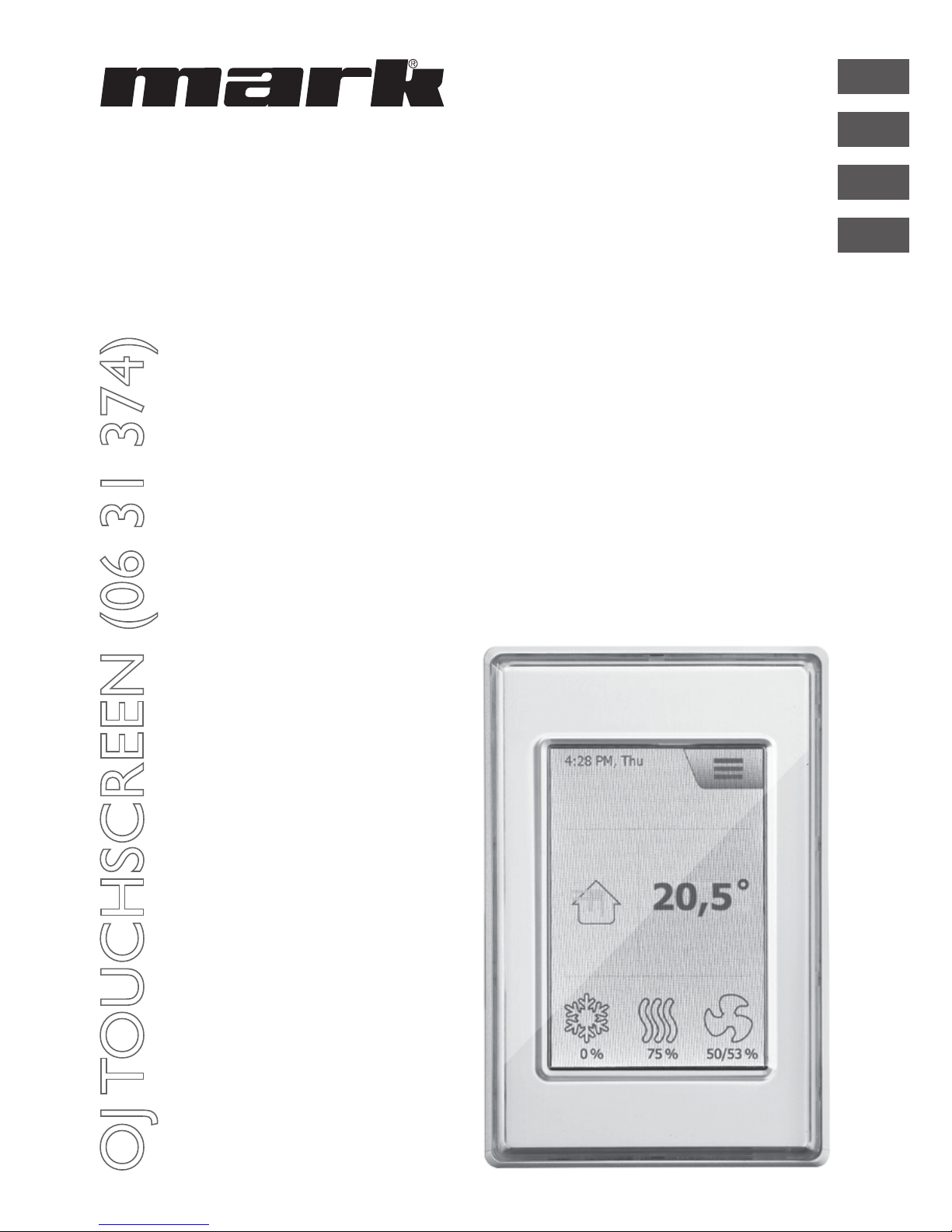
This quick start guide only describes basic settings. If the screen saver
is active, simply touch the screen once to open the home screen. This
screen provides access to elementary functions such as fan speed,
temperature and setup. The time and day of the week are shown in
the top line of the screen.
Below these, an alarm bell is visible if an alarm has been activated. The
house in the middle section of the screen provides access to a simple
overview of temperatures, air volumes and lter pressures. The temperature shown to the right of the house is the temperature setpoint.
The icons shown in the lower part of the screen can be changed and
may therefore differ from those shown in these instructions.
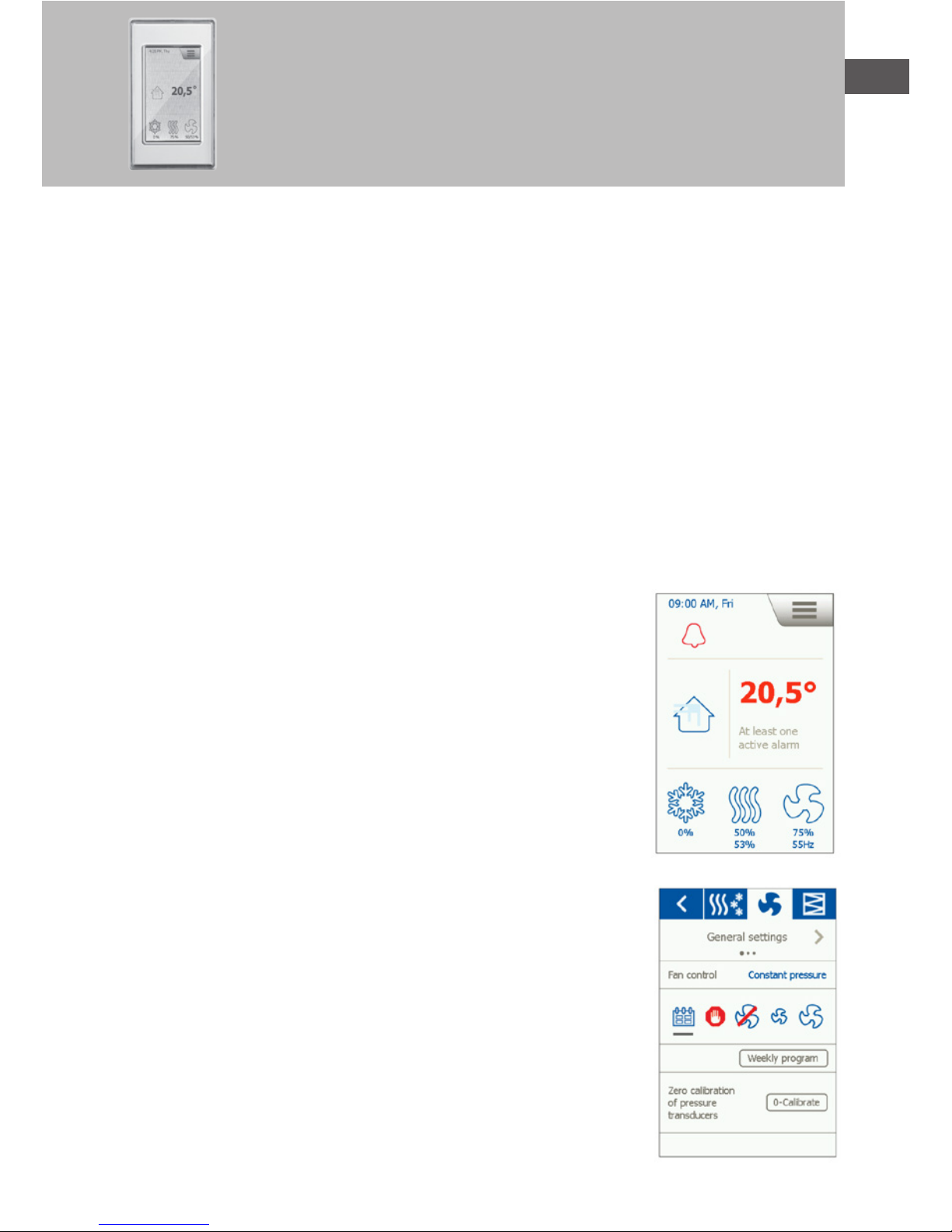
FAN SPEED
To set fan speed, press the fan in the lower part of the home screen.
You can choose between ve predened fan speeds. Off, Auto, Low,
High and Service Stop. If you choose Auto, OJ-AIR2-HMI-35T will follow a predened program. If you choose Low, the predened program
is overridden and the fan operates at low speed. If you choose High,
the predened program is overridden and the fan operates at high
speed. If you choose Off, the fan comes to a complete standstill until
fan speed is again changed. If you choose Service Stop, the system
shuts down and can only be restarted locally from the control panel.
Page 4
4
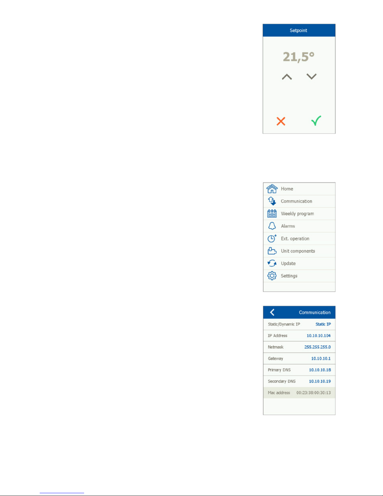
TEMPERATURE
To change the temperature setpoint for the selected control mode,
press the temperature on the panel's home screen. Change the temperature using the arrows and conrm with the green button.
SETTINGS
OJ-AIR2-HMI-35T is used together with an OJ-Air2 Master, and all communication is via the master.
Some settings can be made via the menu icon in the upper right corner of the home screen.
Begin by pressing the menu icon in the upper right corner of the
home screen. The following screen is then displayed:
Home
Press this icon to return to the home screen.
Communication
Here you can congure LAN settings such as static/dynamic IP and
associated addresses.
Page 5
EN
5
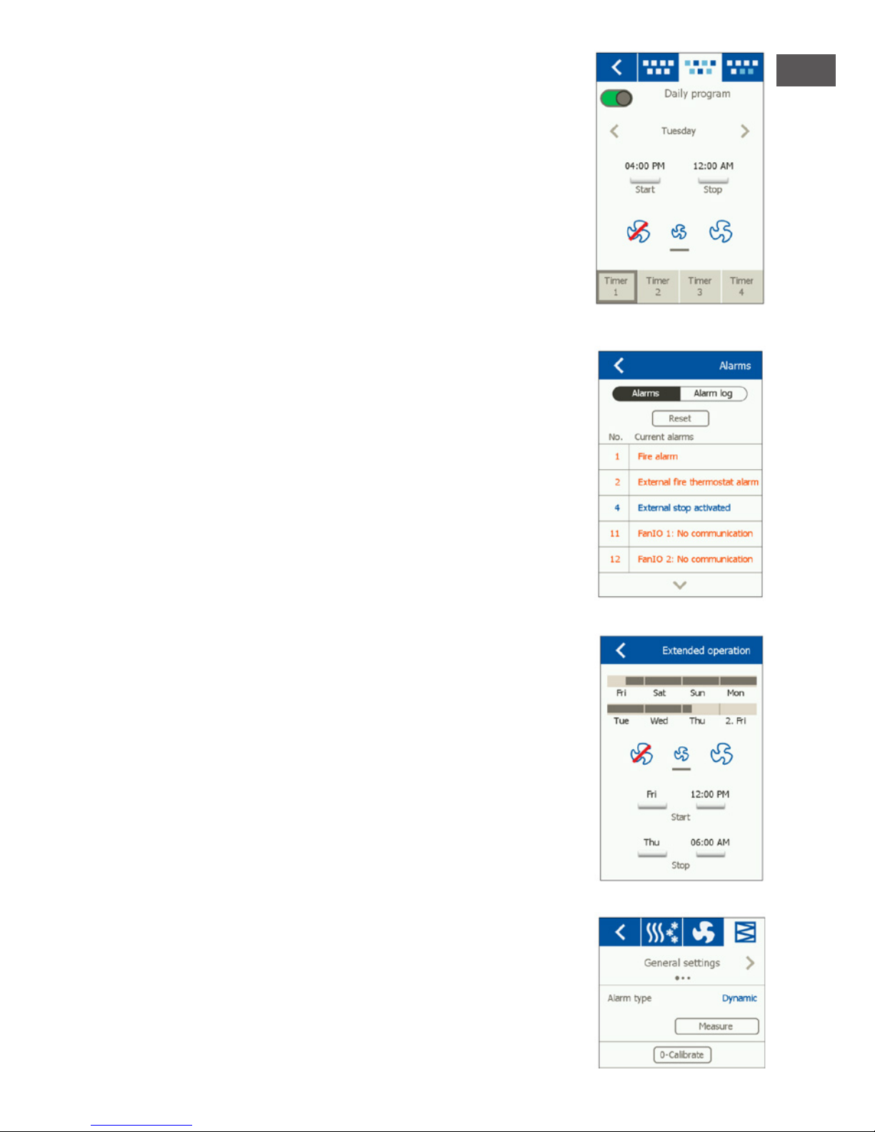
Weekly program
Here you can enter times and modes for the built-in 7-day clock.
Alarms
Here you can view active alarms and an alarm log. In case of an alarm,
this screen can also be accessed via the bell icon on the home screen.
Extended operation
If a different pattern of operation is required for a short period of
time, the weekly program can be overridden. The override period can
last up to a week at most. Once the period has elapsed, the system
returns to standard clockcontrolled operation.
Unit components
Here you can make general settings for the various components that
are installed.
Software update
Here you can check if an SD card inserted into the OJ-Air2 contains
a new software version.
Page 6

6
Settings
The following can be set/viewed:
• Language
• Time & date
• Locking of fan speed during adjustment.
• Setting of fan speed in case of re/smoke extraction
• Setting of screen saver
• Restoration of factory settings
• Setting up the lower part of the screen
• Software version
Language
Here you can choose the language to be used on the screen.
Time & date
Here you can set the time and date for the system.
Adjustment
Here you can lock fan speed during system adjustment. Once the
required air volume has been reached, the fan is locked at its current
speed. This gives the installer the opportunity to adjust the system,
ensuring the right amount of air in the individual rooms without interference from ventilation system regulation.
Page 7
EN
7
Fire
Here you can set the required fan speed in case of re/smoke.
Screen saver
Here you can set the screen saver timeout period.
Factory reset (PIN required)
Here you can restore factory settings.
Home (PIN required)
Here you can congure the icons shown in the lower part of the
home screen.
Page 8

8
About the control
Here you can view information on software versions.
INSTALLATION
OJ-AIR2-HMI-35T can be installed in two ways: either in a wall box/
panel front or directly on a at surface.
Installation on at surface
The back cover of the HMI is equipped with a keyhole-shaped opening which can be used to hang
the unit on a at surface (see Fig. 1). Use a screw that is max. 3.5 mm in diameter with a head no
larger than 9 mm.
Installation in wall box/panel front
If OJ-AIR2-HMI-35T is to be installed in a wall box or panel front, the back cover must be removed.
Firstly, the front cover must be detached by gently releasing the catch on the bottom of the unit
with a at screwdriver and then tipping the cover outwards (see Fig. 2).
Once the front cover has been detached, the two screws holding the back cover in place can be
removed (see g. 3). The back cover can now be detached and the front cover retted. The baseplate
is equipped with several screw holes. The dimensioned drawing (see g. 4) can be used as a drilling
template. The baseplate should be secured with at least two screws tightened to a torque of max.
0.8 Nm. Installation depth is 20 mm.
MODBUS CONNECTION
OJ-AIR2-HMI-35T is connected to the OJ-Air2 Master by means of a Modbus cable. The Modbus cable can be connected to the OJAIR2- HMI-35T by means of the RJ12 6P4C port or four single-wire
screw terminals. Whether the RJ12 6P4C port or screw terminals are used does not inuence the
available functions or operation.
Modbus RJ12 6P4C
Connect the Modbus cable to the Modbus port for a hand terminal on the OJ-Air2 Master and to
the RJ12 6P4C port on the OJ-AIR2- HMI-35T (see g. 5).
Modbus screw terminals
Connect the Modbus cable to the Modbus port for a hand terminal on the OJ-Air2 Master and to
the corresponding screw terminals on the OJ-AIR2-HMI-35T (see g. 6).
RJ12 Screw terminals
1 +24 V
2 GND (earth)
3 Bus “B”
4 Bus “A”
5 +24 V
6 GND (earth)
Page 9

EN
9
TECHNICAL DATA
Supply voltage .............................................................................................................................24 V DC +/-10%
Cable dimensions ................................................................................................................ 10 x max. 0.75 mm²
Relative humidity ......................................................................................................... 0-95% (non-condensing)
Operating temperature ...................................................................................................................... -10/+40°C
Enclosure rating ......................................................................................................................... IP21 (EN 60529)
Port .................................................................................................................................................. 1 x RJ12 6P4C
............................................................................................................................................... 10 x screw terminals
Dimensions ............................................................................................................... 80x121x42 mm (see g. 2)
Installation depth .........................................................................................................................................22 mm
Max. power consumption .......................................................................................................................900 mW
Standby power consumption .................................................................................................................600 mW
SERVICE AND MAINTENANCE
The OJ-Air2-HMI-35T touch panel contains no parts that require service or maintenance. Contact
your supplier in case of problems.
DISPOSAL AND ENVIRONMENTAL PROTECTION
Help protect the environment by disposing of the packaging and redundant products in an environmentally responsible manner.
Products marked with this symbol must not be disposed of along with household refuse but
must be delivered to a waste collection centre in accordance with current local regulations.
CE MARKING
OJ Electronics A/S hereby declares under sole responsibility that the product complies with the following directives of the European Parliament:
EMC - Electromagnetic compatibility: 2004/108/EC
RoHS - Restriction of the use of certain hazardous substances in electrical and electronic equipment:
2011/65/EU
Applied standards
EN 61000-6-2 and EN 61000-6-3 Electromagnetic compatibility (EMC)
Page 10
10
OJ Air2-HMI
Deutsch
VERZEICHNIS DER ABBILDUNGEN
Abb. 1: Montage auf ebener Fläche
Abb. 2: Entfernen der Frontabdeckung
Abb. 3: Entfernen der rückseitigen Abdeckung
Abb. 4: Maßskizze für Montage in Wanddose oder Tafelfront
Abb. 5: Anschluss an Modbus über RJ12 6P4C-Port
Abb. 6: Anschluss an Modbus über Schraubklemmen
EINFÜHRUNG
OJ-AIR2-HMI-35T ist ein Bedienfeld mit Touchscreen und benutzerfreundlicher grascher
Oberäche speziell für die Steuerung von Lüftungsanlagen. Das Panel kommuniziert mit OJ Air2
über eine Modbus-Schnittstelle, die eine einfache Installation gewährleistet.
PRODUKTPROGRAMM
Produkt Typ
OJ-AIR2-HMI-35T 3,5" Touchscreen-Panel
BEDIENUNG
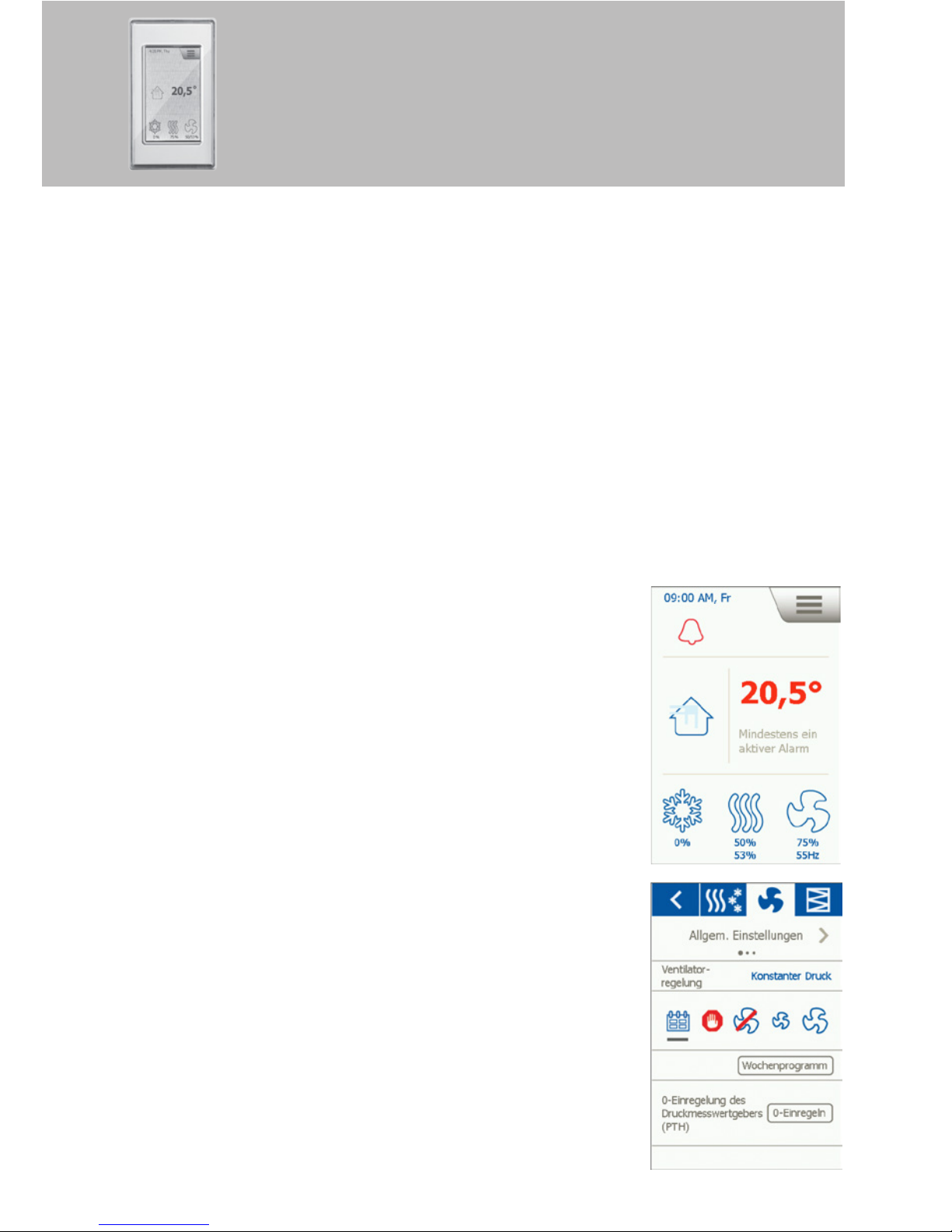
Diese Kurzanleitung enthält nur die Grundeinstellungen. Bei aktivem
Bildschirmschoner für Zugriff auf die Startansicht einfach auf den
Schirm tippen. Dieser Bildschirm ermöglicht Zugriff
auf grundlegende Funktionen wie Lüfterdrehzahl, Temperatur und
Konguration. Uhrzeit und Wochentag werden in der obersten Zeile
am Bildschirm angezeigt. Wurde ein Alarm aktiviert, erscheint unmittelbar darunter eine Alarmglocke. Das Haus-Symbol im mittleren Teil
ermöglicht Zugriff auf ein Übersichtsbild mit Temperatur-, Luftmengen- und Filterdruckangaben. Rechts vom Symbol wird der Temperatursollwert angezeigt. Die Symbole im unteren Teil der Startansicht
können sich ändern und daher von den Abbildungen
abweichen.
LÜFTERDREHZAHL
Die Lüfterdrehzahl wird durch Antippen des Lüftersymbols im unteren Teil der Startansicht eingestellt. Zur Wahl stehen 5 voreingestellte
Lüfterdrehzahlen: Aus, Aut., Niedrig, Hoch und Servicestopp. In der
Einstellung Aut. folgt OJ-AIR2-HMI-35T einem vordenierten Programm. In der Einstellung Niedrig wird das vordenierte Programm
übersteuert, und der Lüfter mit niedriger Drehzahl betrieben. In der
Einstellung Hoch wird das vordenierte Programm übersteuert, und
der Lüfter mit hoher Drehzahl betrieben. In der Einstellung Aus steht
der Lüfter still, bis die Einstellung wieder geändert wird. In der Einstellung Servicestopp stoppt die Anlage und kann nur lokal vom Bedienfeld gestartet werden.
Page 11
DU
11
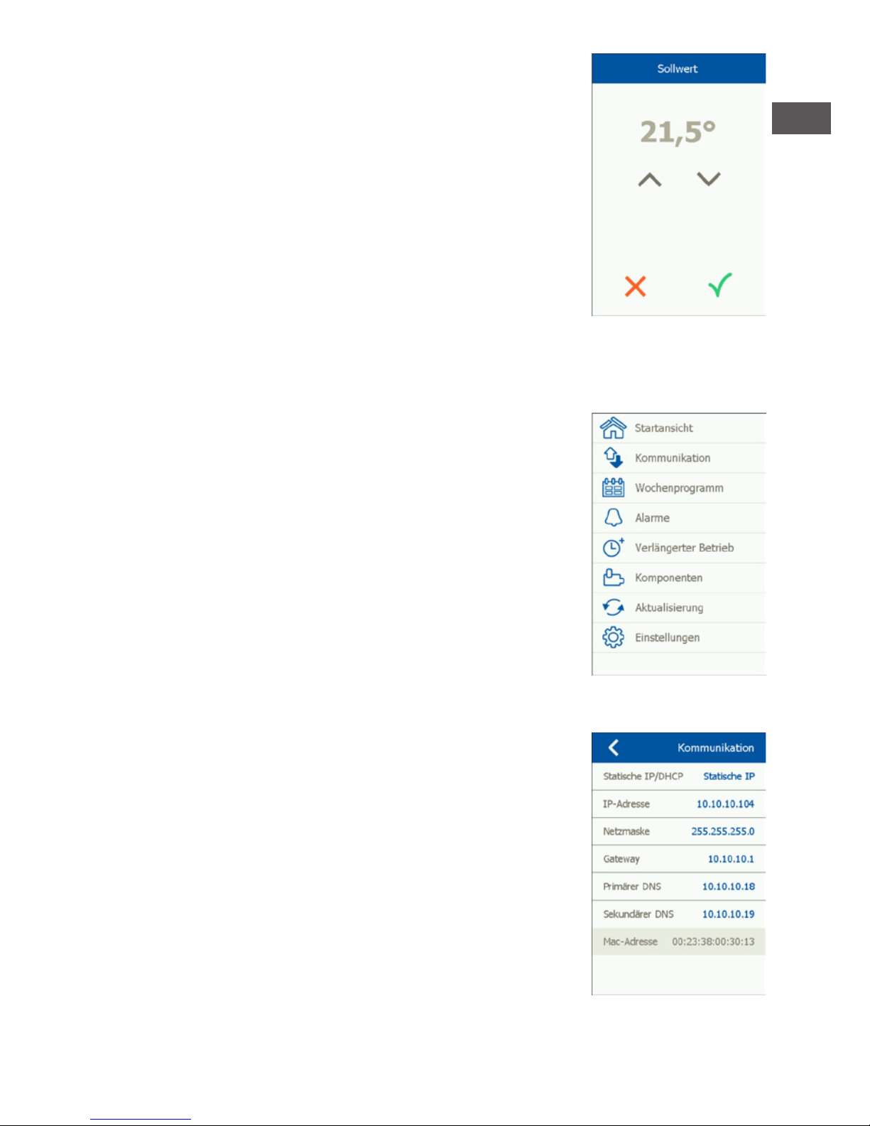
TEMPERATUR
Um den Temperatursollwert für den eingestellten Regelzustand zu
ändern, auf die Temperatur in der Startansicht tippen. Die Temperatur
mit den Pfeiltasten ändern und mit der grünen Taste bestätigen.
KONFIGURATION
OJ-AIR2-HMI-35T wird in Verbindung mit einem OJ Air2 Master angewandt, über den die gesamte
Konguration vorgenommen wird. Bestimmte Kongurationen können über das Menüsymbol in
der rechten oberen Ecke der Startansicht erfolgen. Zuerst das
Menüsymbol in der rechten oberen Ecke der Startansicht antippen.
Folgender Bildschirm wird angezeigt: Folgender Bildschirm wird angezeigt:
Startansicht
Dieses Symbol antippen, um zur Startansicht zurückzukehren.
Kommunikation
Hier werden die LAN-Einstellungen, wie zum Beispiel statische/
dynamische IP und zugehörige Adressen vorgenommen.
Page 12

12
Wochenprogramm
Hier werden die Zeitpunkte und Modi für die eingebaute Wochenuhr
eingestellt.
Alarme
Hier werden aktive Alarme und Alarmlog angezeigt. Im Alarmfall kann
dieser Bildschirm auch über das Glockensymbol in der Startansicht
aktiviert werden.
Verlängerter Betrieb
Soll für einen kürzeren Zeitraum ein anderes Betriebsmuster benutzt werden, lässt sich die Wochenuhr übersteuern. Die Laufzeit der
Übersteuerung darf maximal eine Woche betragen. Nach Ablauf dieser Periode kehrt die Steuerung zum normalen Uhrbetrieb zurück.
Komponenten
Hier erfolgen die allgemeinen Einstellungen für die verschiedenen
installierten Komponenten.
Aktualisierung
Gegebenenfalls die SD-Karte in OJ Air2 einsetzen, um neue Software
abzurufen.
Page 13

DU
13
Einstellungen
Folgendes lässt sich einstellen/anzeigen:
• Sprache
• Uhrzeit und Datum
• Festlegen der Lüfterdrehzahl beim Einregeln.
• Einstellen der Lüfterdrehzahl bei Brand/Rauchabsaugung
• Einstellung des Bildschirmschoners
• Zurücksetzen auf die Werkseinstellung
• Konguration des unteren Teils der Startansicht
• Softwareversion
Sprache
Hier lässt sich die Bildschirmsprache ändern.
Zeit und Datum
Hier kann Uhrzeit und Datum der Anlage geändert werden.
Einregeln
Hier kann die Lüfterdrehzahl während des Einregelns festgelegt werden. Nach Erreichen der gewünschten Luftmenge wird der Lüfter
auf die aktuelle Drehzahl festgelegt. Dies ermöglicht es dem Montagetechniker die richtige Luftmenge in den einzelnen Räumen einzuregeln und festzulegen, ohne Einussnahme von der Lüftungsanla-
genregelung.
Page 14

14
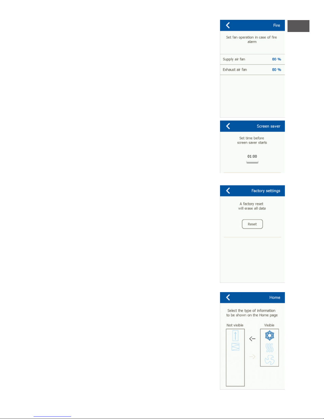
Brand
Hier wird die Lüfterdrehzahl im Fall von Brand/Rauch eingestellt.
Bildschirmschoner
Einstellungen für Bildschirmschoner-Timeout.
Zurücksetzen auf die Werkseinstellung (PIN-Code erforderlich)
Zurücksetzen auf die Werkseinstellung.
Startansicht (PIN-Code erforderlich)
Konguration der Symbole im unteren Teil der Startansicht.
Page 15

DU
15
Über die Steuerung
Infos über Softwareversionen.
INSTALLATION
OJ-AIR2-HMI-35T kann auf zwei Arten montiert werden: Entweder
in Wanddose/Tafelfront oder direkt auf einer ebenen Fläche.
Montage auf ebener Fläche
Auf HMIs Rückseite ndet sich eine Aussparung (Schlüsselloch) zur Aufhängung auf einer ebenen
Fläche (siehe Abb. 1). Der max. Schraubendurchmesser ist 3,5 mm und der des Schraubenkopfs sollte
nicht größer als 9 mm sein.
Montage in Wanddose/Tafelfront
Soll OJ-AIR2-HMI-35T in einer Wanddose oder Tafelfront montiert werden, ist die rückseitige Abdeckung zu entfernen. Zuerst ist die Frontabdeckung zu entfernen, in dem auf der Unterseite des
HMIs vorsichtig mit einem achen Schraubendreher die Sperrklinke der Front gelöst und dann die
Front hochgewippt wird (siehe Abb. 2). Ist die Front demontiert, die zwei die rückseitige Abdeckung
festhaltenden Schrauben ganz lösen (siehe Abb. 3). Jetzt kann die rückseitige Abdeckung entfernt
und das HMI wieder zusammengebaut werden. Die Bodenplatte ist mit mehreren Schraublöchern
versehen. Die Maßskizze zur Hilfe nehmen (siehe Abb. 4). Die Bodenplatte ist mit mindestens zwei
Schrauben mit einem Drehmoment von max. 0,8 Nm zu befestigen. Einbautiefe ist 20 mm.
MODBUS-ANSCHLUSS
OJ-AIR2-HMI-35T ist über Modbuskabel an den OJ Air2 Master anzuschließen. Das Modbuskabel
kann an OJ-AIR2-HMI-35T entweder über ein RJ12 6P4C-Port oder vier Einzeldraht-Schraubklemmen angeschlossen werden. Auf die zugänglichen Funktionen oder die Bedienung hat es keinen
Einuss, ob ein RJ12 6P4C-Port oder Schraubklemmen benutzt werden.
Modbus RJ12 6P4C
Das Modbuskabel an das Modbus-Port zum Handterminal am OJ Air2 Master und am RJ12 6P4C-
Port des OJ-AIR2-HMI-35T anschließen (siehe Abb. 5).
Modbus-Schraubklemmen
Das Modbuskabel an das Modbus-Port zum Handterminal am OJ Air2 Master und an den entsprechenden Schraubklemmen des OJAIR2- HMI-35T anschließen (siehe Abb. 6).
RJ12 Schraubklemmen
1 +24 V
2 GND (Masse)
3 Bus „B“
4 Bus „A“
5 +24 V
6 GND (Masse)
Page 16

16
TECHNISCHE DATEN
Spannungsversorgung ...................................................................................................................... 24 V= ±10 %
Kabelabmessungen .............................................................................................................. 10 × max. 0,75 mm²
Relative Luftfeuchtigkeit ....................................................................................0-95 % (nicht kondensierend)
Betriebstemperatur. ............................................................................................................................ -10/+40 °C
Schutzart ..................................................................................................................................... IP21 (EN 60529)
Port ..................................................................................................................................................1 × RJ12 6P4C
.................................................................................................................................................10 Schraubklemmen
Abmessungen .................................................................................................... 80×121×42 mm (siehe Abb. 2)
Einbautiefe..................................................................................................................................................... 22 mm
Max. Stromverbrauch ..............................................................................................................................900 mW
Standby-Stromverbrauch ........................................................................................................................600 mW
SERVICE UND WARTUNG
Das OJ-Air2-HMI-35T-Touchpanel enthält keine Service oder Wartung erfordernden Teile. Bei Problemen bitte mit dem Zulieferer Kontakt aufnehmen.
ENTSORGUNG UND UMWELTSCHUTZ
Helfen Sie mit, die Umwelt durch umweltgerechte Entsorgung von Verpackung und gebrauchten
Produkten zu schützen.
Produkte mit dieser Kennzeichnung dürfen nicht als normaler Hausmüll entsorgt werden,
sondern sind gemäß den geltenden lokalen Vorschriften gesondert einzusammeln.
CE-KENNZEICHNUNG
OJ Electronics A/S erklärt hiermit verantwortlich, dass dieses Produkt den folgenden Richtlinien des
Europäischen Parlaments entspricht.
EMV – Elektromagnetische Verträglichkeit: 2004/108/EG
RoHS – Beschränkung der Verwendung bestimmter gefährlicher
Stoffe in Elektro- und Elektronikgeräten: 2011/65/EU
Angewandte Normen
EN 61000-6-2 und EN 61000-6-3 Elektromagnetische Verträglichkeit (EMV)
Page 17

FR
17
OJ Air2-HMI
Français
LISTE DES FIGURES
Fig. 1: Installation sur surface plane
Fig. 2: Enlever le couvercle frontal
Fig. 3: Enlever le couvercle arrière
Fig. 4: Dessin avec dimensions pour faciliter l'installation dans un boîtier mural ou le devant d'un
panneau
Fig. 5: Raccordement du Modbus par le port RJ12 6P4C
Fig. 6: Connexion du Modbus en utilisant les bornes à vis I
INTRODUCTION
L'OJ-AIR2-HMI-35T est un panneau-écran tactile avec une interface utilisateur conviviale et qui a été
développé spécialement pour le contrôle de systèmes de ventilation. Le panneau communique avec
le système OJ-Air2 par une interface Modbus assurant une installation facile.
GAMME DE PRODUITS
Produit Typ
OJ-AIR2-HMI-35T Écran tactile de 3,5”
FONCTIONNEMENT
Ce guide rapide pour le démarrage ne décrit que des réglages de base.
Si l'écran de veille est actif, touchez simplement à l'écran pour afcher
l'écran d'accueil.
Cet écran fournit l'accès à des fonctions de base comme la vitesse
du ventilateur, la température et le réglage. L'heure et la journée de
la semaine sont afchées dans la ligne du haut de l'écran. Sous ces
derniers, une cloche d'alarme devient visible si une alarme est activée.
La maison dans la section du centre de l'écran fournit un accès à un
aperçu simple des températures, des volumes d'air et des pressions
de ltres. La température montrée à la droite de la maison est le point
de consigne de la température. Les icônes de la partie inférieure de
l'écran peuvent être remplacées et peuvent donc différer de celles
montrées dans ces instructions.
VITESSE DU VENTILATEUR
Pour régler la vitesse du ventilateur, appuyez sur le ventilateur dans la
partie inférieure de l'écran d'accueil. Vous pouvez choisir parmi quatre
vitesses prédénies du ventilateur, Arrêt, Auto, Lent, Rapide et Arrêt
pour entretien. Si vous choisissez Auto, l'OJ-AIR2- HMI-35T suivra un
programme prédéni. Si vous choisissez Lent, le programme prédéni
est contourné et le ventilateur fonctionne à basse vitesse. Si vous
choisissez Rapide, le programme prédéni est contourné et le ventilateur fonctionne à haute vitesse. Si vous choisissez Arrêt, le ventilateur
s'arrête complètement jusqu'à ce que la vitesse du ventilateur soit
changée à nouveau. Si vous choisissez Arrêt pour entretien, le système
complet s'arrête et ne peut être redémarré localement que par le
panneau de commande.
Page 18

18
TEMPÉRATURE
Pour changer le point de consigne de la température pour le mode
de contrôle choisi, touchez à la température à l'écran d'accueil du
panneau. Changez la température en utilisant les èches et conrmez
avec le bouton vert.
RÉGLAGES
L'OJ-AIR2-HMI-35T est utilisé avec l'OJ-Air2 Master et toute la communication se fait par le maître
(master). Certains réglages peuvent être faits par l'icône de menu
dans le coin droit supérieur de l'écran d'accueil.
En premier, appuyez sur l'icône de menu dans le coin droit supérieur
de l'écran d'accueil. L'écran suivant s'afchera :
Écran d'accueil
Touchez à cette icône pour retourner à l'écran d'accueil.
Communication
Ici vous pouvez congurer les réglages LAN comme IP statique/
dynamique et les adresses associées.
Page 19

FR
19
Programme hebdomadaire
Ici vous pouvez entrer les heures et les modes pour l'horloge interne
de 7 jours.
Alarmes
Ici vous pouvez voir les alarmes actives et le journal d’alarme. Si
une alarme est active, vous pouvez accéder à cet écran par l'icône de
cloche sur l'écran d'accueil.
Opératation prolongée
Si un modèle différent d'opération est requis pour une courte durée,
le programme hebdomadaire peut être contourné. La période de
contournement peut durée jusqu'à une semaine au plus. Une fois
la période écoulée, le système retourne à l'opération standard
contrôlée par horloge.
Composantes de l'unité
Ici vous pouvez faire des réglages généraux pour les diverses composantes qui sont installées.
Mise à jour du logiciel
Ici vous pouvez vérier si une carte SD insérée dans l'OJ-Air2
contient une nouvelle version du logiciel.
Page 20

20
Réglages
Les réglages suivants peuvent être faits/vus :
• Langue
• Heure et date
• Verrouillage de la vitesse du ventilateur pendant le réglage.
• Réglage de la vitesse du ventilateur en cas de feu/extraction de
fumée
• Réglage de l'écran de veille
• Rétablissement des réglages d'usine
• Réglage de la partie inférieure de l'écran
• Version du logiciel
Langue
Ici vous pouvez choisir la langue qui sera utilisée pour l'afchage.
Heure et date
Ici vous pouvez régler l'heure et la date pour le système.
Réglage
Ici vous pouvez verrouiller la vitesse du ventilateur pendant
le réglage du système. Quand le volume d'air est atteint, le ventilateur
se verrouille à sa vitesse actuelle. Ceci donne à l'installateur
l'opportunité de régler le système en assurant un volume d'air adéquat dans les pièces individuelles sans interférence de la régulation
du système de ventilation.
Page 21

FR
21
Feu
Ici vous pouvez régler la vitesse du ventilateur en cas de feu/de
fumée.
Écran de veille
Ici vous pouvez régler la période de temps mort de l'écran de veille.
Réinitialisation aux valeurs d'usine (NIP requis)
Ici vous pouvez rétablir les réglages d'usine.
Écran d'accueil (NIP requis)
Ici vous pouvez congurer les icônes afchées dans la partie inférieure de l'écran d'accueil.
Page 22

22
À propos commande
Ici vous pouvez voir l'information à propos des versions du logiciel.
INSTALLATION
L'OJ-AIR2-HMI-35T peut être installé de deux façons : soit dans
un boîtier mural/devant de panneau ou directement sur une surface
plane.
Installation sur surface plane
Le couvercle arrière de l'HMI est muni d'une ouverture en forme de trou de serrure qui peut être
utilisée pour suspendre l'appareil à une surface plane (voir g. 1). Utilisez une vis ayant un diamètre
max. de 3,5 mm avec une tête d'une largeur d'au plus 9 mm.
Installation dans un boîtier mural/devant de panneau
Si l'OJ-AIR2-HMI-35T doit être installé dans un boîtier mural ou un devant de panneau, le couvercle
arrière doit être enlevé. En premier, le couvercle avant doit être détaché en relâchant doucement
le loquet au bas de l'appareil avec un tournevis plat puis en basculant le couvercle vers l'extérieur
(voir g. 2). Une fois que le couvercle avant est retiré, les deux vis qui retiennent le couvercle arrière
peuvent être enlevées (voir g. 3). Le couvercle arrière peut maintenant être enlevé et le couvercle
avant remis en place. La plaque de base est munie de plusieurs trous pour des vis. Le dessin avec
dimensions (voir g. 4) peut être utilisé comme gabarit de perçage. La plaque de base devrait être
xée avec au moins deux vis serrées avec un couple max. de 0,8 Nm. La profondeur d'installation
est 20 mm.
CONNEXION MODBUS
L'OJ-AIR2-HMI-35T est relié à l'OJ-Air2 Master par un câble Modbus. Le câble Modbus peut être
connecté à l'OJ-AIR2- HMI-35T par le port RJ12 6P4C ou par quatre bornes à vis pour conducteur unique. Le fait d'utiliser le port RJ12 6P4C ou les bornes à vis n'inuence pas les fonctions
d'opérations disponibles.
RJ12 6P4C Modbus
Connectez le câble Modbus au port Modbus pour un terminal mobile sur l'OJ-Air2 Master et au
port RJ12 6P4C sur l'OJ-AIR2- HMI-35T (voir g. 5).
Bornes à vis Modbus
Connectez le câble Modbus au port Modbus pour un terminal mobile sur l'OJ-Air2 Master et aux
bornes à vis correspondantes sur l'OJ-AIR2-HMI-35T (voir g. 6).
RJ12 Bornes à vis
1 +24 V
2 GND (terre)
3 Bus „B“
4 Bus „A“
5 +24 V
6 GND (terre)
Page 23

FR
23
CARACTÉRISTIQUES TECHNIQUES
Tension d'alimentation .................................................................................................................... 24 V= ±10 %
Dimensions du câble .......................................................................................................... 10 × max. 0,75 mm²
Humidité relative ....................................................................................................0-95 % (sans condensation)
Température de fonctionnement. .................................................................................................... -10/+40 °C
Norme du boîtier...................................................................................................................... IP21 (EN 60529)
Port ..................................................................................................................................................1 × RJ12 6P4C
.......................................................................................................................................................10 x bornes à vis
Dimensions ............................................................................................................. 80×121×42 mm (voir g. 2)
Profondeur d'installation ...........................................................................................................................22 mm
Consommation de puissance max .......................................................................................................900 mW
Consommation de puissance en attente ............................................................................................600 mW
SERVICE ET ENTRETIEN
Le panneau tactile de l'OJ-Air2-HMI-35T ne contient pas de pièces qui demandent un service ou un
entretien. Communiquez avec votre fournisseur pour les problèmes.
MISE AU REBUT ET PROTECTION DE L’ENVIRONNEMENT
Aidez à protéger l’environnement en rebutant l’emballage et les produits superus d’une façon
favorable à l’environnement.
Les produits marqués de ce symbole ne doivent pas être rebutés avec les déchets domestiques, mais doivent être livrés à un centre de collecte de rebuts en conformité avec les
règlements locaux en vigueur.
HOMOLOGATION CE
OJ Electronics A/S déclare par la présente sous son unique responsabilité que le produit est conforme aux directives suivantes du Parlement européen :
CEM - Compatibilité électromagnétique : 2004/108/CE
RoHS - limitation de l'utilisation de certaines substances dangereuses dans les équipements électriques et électroniques : 2011/65/UE
Normes appliquées
EN 61000-6-2 et EN 61000-6-3, compatibilité électromagnétique (CEM)
Page 24

24
OJ Air2-HMI
Nederlands
LIJST VAN FIGUREN
Fig. 1: Installatie op een vlak oppervlak
Fig. 2: De voorklep verwijderen
Fig. 3: De achterklep verwijderen
Fig. 4: Maattekening om de installatie in een wanddoos of paneelfront te vergemakkelijken
Fig. 5: Modbus aansluiten via de RJ12 6P4C-poort
Fig. 6: Modbus aansluiten via de schroefklemmen
INTRODUCTIE
OJ-AIR2-HMI-35T is een aanraakscherm met gebruiksvriendelijke grasche gebruikersinterface,
speciaal ontwikkeld voor het regelen van ventilatiesystemen. Het paneel communiceert met het OJAir2-systeem via een Modbus-interface, waardoor een eenvoudige installatie mogelijk is.
PRODUCT PROGRAMMA
Product Type
OJ-AIR2-HMI-35T 3.5” touchscreen paneel
WERKING
Deze snelstartgids beschrijft alleen de basisinstellingen. Als de schermbeveiliging actief is, raakt u eenvoudig het scherm aan om het startscherm te openen. Dit scherm biedt toegang tot elementaire functies
zoals ventilatorsnelheid, temperatuur en setup. De tijd en dag van de
week worden in de bovenste regel van het scherm weergegeven.
Onder deze is een alarmbel zichtbaar als een alarm is geactiveerd.
Het huis in het middengedeelte van het scherm biedt toegang tot een
eenvoudig overzicht van temperaturen, luchtvolumes en lterdrukken.
De temperatuur rechts van het huis is het temperatuurinstelpunt. De
pictogrammen in het onderste deel van het scherm kunnen worden
gewijzigd en kunnen daarom verschillen van de pictogrammen in deze
instructies.
VENTILATOR SNELHEID
Om de ventilatorsnelheid in te stellen, drukt u op de ventilator in het
onderste gedeelte van het startscherm. U kunt kiezen uit vijf vooraf
gedenieerde ventilatorsnelheden. Uit, Auto, Laag, Hoog en Servicestop. Als u Auto kiest, zal OJ-AIR2-HMI-35T een vooraf gedenieerd
programma volgen. Als u Laag kiest, wordt het vooraf gedenieerde
programma overschreven en werkt de ventilator op lage snelheid.
Als u Hoog kiest, wordt het vooraf gedenieerde programma overschreven en werkt de ventilator op hoge snelheid. Als u Uit kiest, blijft
de ventilator volledig stilstaan totdat de ventilatorsnelheid opnieuw
wordt gewijzigd. Als u Service Stop kiest, wordt het systeem afgesloten en kan het alleen lokaal opnieuw worden opgestart via het
bedieningspaneel.
Page 25

NL
25
TEMPERATUUR
Om de temperatuursetpoint voor de geselecteerde regelmodus te
wijzigen, drukt u op de temperatuur op het startscherm van het paneel. Verander de temperatuur met behulp van de pijlen en bevestig
met de groene knop.
INSTELLINGEN
OJ-AIR2-HMI-35T wordt gebruikt in combinatie met een OJ-Air2 Master, en alle communicatie
verloopt via de master. Sommige instellingen kunnen worden gemaakt via het menupictogram in de
rechterbovenhoek van het startscherm.
Begin door op het menupictogram in de rechterbovenhoek van het
startscherm te drukken. Het volgende scherm wordt vervolgens
weergegeven:
Home
Druk op dit pictogram om terug te keren naar het startscherm.
Communicatie
Hier kunt u LAN-instellingen congureren zoals statisch / dynamisch
IP en bijbehorende adressen.
Page 26

26
Weekprogramma
Hier kunt u tijden en modi invoeren voor de ingebouwde 7-dagenklok.
Alarm
Hier kunt u actieve alarmen en een alarmlog bekijken. In geval van
een alarm is dit scherm ook toegankelijk via het belpictogram op het
startscherm.
Uitgebreide werking
Als er voor een korte periode een ander werkingspatroon nodig is,
kan het wekelijkse programma worden opgeheven. De ophefngsperiode kan maximaal een week duren. Nadat de periode is verstreken,
keert het systeem terug naar de standaard klokgestuurde werking.
Unit componenten
Hier kunt u algemene instellingen maken voor de verschillende com-
ponenten die zijn geïnstalleerd.
Software-update
Hier kunt u controleren of een SD-kaart in de OJ-Air2 een nieuwe
softwareversie bevat.
Page 27

NL
27
Instellingen
Het volgende kan worden ingesteld / bekeken:
• Taal
• Tijd & datum
• Ventilatorsnelheid vergrendelen tijdens afstelling.
• Schermbeveiliging instellen
• Herstel van fabrieksinstellingen
• Het onderste deel van het scherm instellen
• Software versie
Taal
Hier kunt u de taal kiezen die op het scherm moet worden gebruikt.
Tijd & datum
Hier kunt u de tijd en datum voor het systeem instellen.
Aanpassing
Hier kunt u de ventilatorsnelheid vergrendelen tijdens systeemaanpassing. Zodra het vereiste luchtvolume is bereikt, wordt de ventilator op zijn huidige snelheid vergrendeld. Dit geeft de installateur de
mogelijkheid om het systeem aan te passen en zorgt voor de juiste
hoeveelheid lucht in de afzonderlijke ruimtes zonder te interfereren
met de regels van het ventilatiesysteem.
Page 28

28
Brand
Hier kunt u de vereiste ventilatorsnelheid instellen in geval van
brand/rook.
Screensaver
Hier kunt u de time-outperiode voor de schermbeveiliging instellen.
Fabrieksreset (PIN vereist)
Hier kunt u de fabrieksinstellingen herstellen.
Home (PIN vereist)
Hier kunt u de pictogrammen congureren die in het onderste
gedeelte van het startscherm worden getoond.
Page 29

NL
29
Over de besturing
Hier kunt u informatie over softwareversies bekijken.
INSTALLATIE
OJ-AIR2-HMI-35T kan op twee manieren worden geïnstalleerd: in
een wanddoos / paneelfront of direct op een plat oppervlak.
Installatie op een vlak oppervlak
De achterkant van de HMI is uitgerust met een sleutelgatvormige opening die kan worden gebruikt
om de eenheid op een plat oppervlak op te hangen (zie afbeelding 1). Gebruik een schroef die max
is. 3,5 mm in diameter met een kop niet groter dan 9 mm.
Installatie in muurdoos / paneelfront
Als OJ-AIR2-HMI-35T in een muurdoos of paneelfront moet worden geïnstalleerd, moet de achterklep worden verwijderd. Ten eerste moet de voorklep worden verwijderd door voorzichtig de
greep aan de onderkant van de eenheid los te maken met een platte schroevendraaier en de kap
vervolgens naar buiten te kantelen (zie afb. 2).
Nadat de voorklep is verwijderd, kunnen de twee schroeven die de achtercover op zijn plaats houden worden verwijderd (zie g. 3). De achterklep kan nu worden losgemaakt en de voorklep kan
worden geplaatst. De bodemplaat is uitgerust met verschillende schroefgaten. De maattekening (zie
g. 4) kan als boorsjabloon worden gebruikt. De grondplaat moet worden vastgezet met minimaal
twee schroeven die zijn vastgedraaid tot een koppel van max. 0,8 Nm. De inbouwdiepte is 20 mm.
MODBUS VERBINDING
OJ-AIR2-HMI-35T is verbonden met de OJ-Air2 Master door middel van een Modbus-kabel. De
Modbus-kabel kan worden aangesloten op de OJAIR2- HMI-35T door middel van de RJ12 6P4Cpoort of vier afzonderlijke kabels schroef terminals. Of de RJ12 6P4C-poort of de schroefaansluitingen worden gebruikt, heeft geen invloed op de beschikbare functies of werking.
Modbus RJ12 6P4C
Sluit de Modbus-kabel aan op de Modbus-poort voor een handterminal op de OJ-Air2 Master en op
de RJ12 6P4C-poort op de OJ-AIR2- HMI-35T (zie g. 5).
Modbus-schroefaansluitingen
Sluit de Modbus-kabel aan op de Modbus-poort voor een handterminal op de OJ-Air2 Master en op
de bijbehorende schroefaansluitingen op de OJ-AIR2-HMI-35T (zie g. 6).
RJ12 Schroef terminals
1 +24 V
2 GND (aarde)
3 Bus "B"
4 Bus "A"
5 +24 V
6 GND (aarde)
Page 30

30
TECHNISCHE DATA
Voedingsspanning .......................................................................................................................24 V DC +/-10%
Kabeldimensies .................................................................................................................... 10 x max. 0.75 mm²
Relatieve vochtigheid ..................................................................................0-95% (Zonder condensvorming)
Bedrijfstemperatuur ............................................................................................................................ -10/+40°C
Behuizing rating ......................................................................................................................... IP21 (EN 60529)
Poort ................................................................................................................................................ 1 x RJ12 6P4C
.............................................................................................................................................10 x schroef terminals
Dimensies .................................................................................................................. 80x121x42 mm (zie g. 2)
Installatie diepte...........................................................................................................................................22 mm
Max. energieverbruik ...............................................................................................................................900 mW
Stroomverbruik in stand-by ...................................................................................................................600 mW
SERVICE EN ONDERHOUD
Het OJ-Air2-HMI-35T aanraakpaneel bevat geen onderdelen die onderhoud of service vereisen.
Neem contact op met uw leverancier in geval van problemen.
BESCHERMING VAN AFVAL EN MILIEUBEHEER
Bescherm het milieu door de verpakking en overtollige producten op een milieuvriendelijke manier
weg te gooien.
Producten die met dit symbool zijn gemarkeerd, mogen niet samen met huisafval worden
weggegooid, maar moeten worden ingeleverd bij een afvalverzamelcentrum in overeenstemming met de geldende plaatselijke voorschriften.
CE-MARKERING
OJ Electronics A / S verklaart hierbij op eigen verantwoordelijkheid dat het product voldoet aan de
volgende richtlijnen van het Europees Parlement:
EMC - Elektromagnetische compatibiliteit: 2004/108 / EG
RoHS - Beperking van het gebruik van bepaalde gevaarlijke stoffen in elektrische en elektronische
apparatuur: 2011/65 / EU
Toegepaste normen
EN 61000-6-2 en EN 61000-6-3 Elektromagnetische compatibiliteit (EMC)
Page 31

31
ILLUSTRATIONS
Fig. 1 Installation on at surface
Fig. 2 Removing the front cover
Page 32

32
Fig. 3 Removing the back cover
Fig. 4 Dimensioned drawing to facilitate installation
in wall box or panel front
Page 33

33
Fig. 5 Connecting Modbus via the RJ12 6P4C port
Fig. 6 Connecting Modbus via the screw terminals
Page 34

34
Page 35

35
Page 36

36
MARK BV
BENEDEN VERLAAT 87-89
VEENDAM (NEDERLAND)
POSTBUS 13, 9640 AA VEENDAM
TELEFOON +31(0)598 656600
FAX +31 (0)598 624584
info@mark.nl
www.mark.nl
MARK EIRE BV
COOLEA, MACROOM
CO. CORK
P12 W660 (IRELAND)
PHONE +353 (0)26 45334
FAX +353 (0)26 45383
sales@markeire.com
www.markeire.com
MARK BELGIUM b.v.b.a.
ENERGIELAAN 12
2950 KAPELLEN
(BELGIË/BELGIQUE)
TELEFOON +32 (0)3 6669254
FAX +32 (0)3 6666578
info@markbelgium.be
www.markbelgium.be
MARK DEUTSCHLAND GmbH
MAX-PLANCK-STRASSE 16
46446 EMMERICH AM RHEIN
(DEUTSCHLAND)
TELEFON +49 (0)2822 97728-0
TELEFAX +49 (0)2822 97728-10
info@mark.de
www.mark.de
MARK POLSKA Sp. z o.o
UL. JASNOGÓRSKA 27
42-202 CZĘSTOCHOWA ( P O L S KA )
PHONE +48 34 3683443
FAX +48 34 3683553
info@markpolska.pl
www.markpolska.pl
S.C. MARK ROMANIA S.R.L.
STR. KOS KAROLY NR. 1 A
540297 TARGU MURES
(ROMANIA)
TEL/FAX +40 (0)265-266.332
ofce@markromania.ro
www.markromania.ro
CERTIFICATION N°: 17.07.011
AIRSTREAM
CERTIFICATION N°: 17.07.011
AIRSTREAM
CERTIFICATION N°: 17.07.011
AIRSTREAM
 Loading...