

Page 1
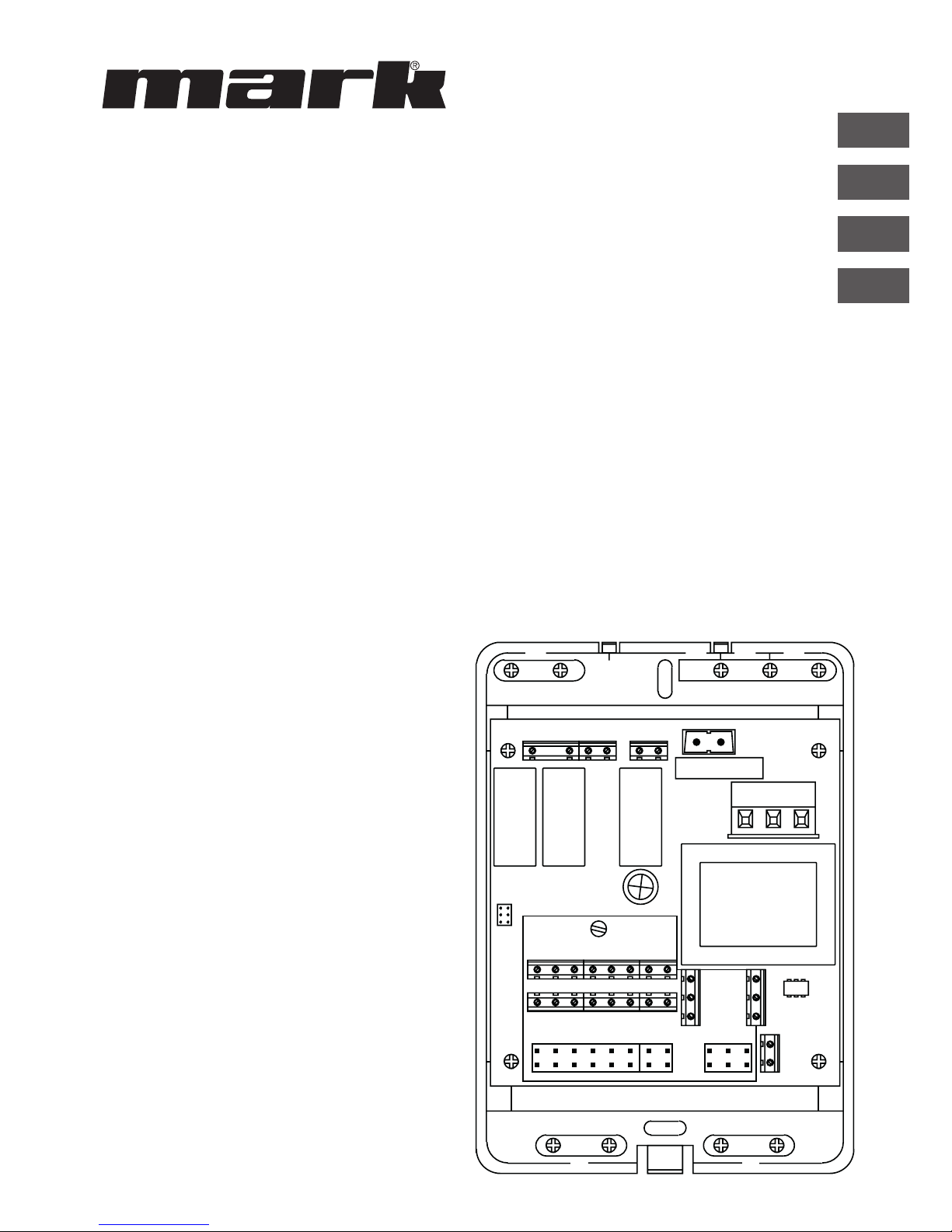
Interface+ module
0664014_R03
06 29 188
Technisches Handbuch
Technical manual
Technisches Handbuch
Livret technique
Technisch boek
DE
EN
FR
NL
Page 2

2
Page 3

3
Read this document before
installing the appliance
Warning
Incorrect installation, adjustment, alteration, repair or maintenance work may lead to material
damage or injury. All work must be carried out by certied, qualied professionals. If the
appliance is not positioned in accordance with the instructions, the warranty shall be rendered
void. This appliance is not intended for use by children or persons with a physical, sensory or
mental handicap, or who lack the required experience or expertise, unless they are supervised or
have been instructed in the use of the appliance by somebody who is responsible for their safety.
Children must be supervised to ensure that they do not play with the appliance.
If the manual refers to an image or table, a number will be shown between square brackets, for
example [3].The number refers to images and tables at the back of the manual with the stated
number.
1.0 General
1.1 All rights reserved
The manufacturer has a policy of continuous product improvement and reserves the right to make
changes to the specications without prior notice. The technical details are considered correct but
do not form the basis for a contract or warranty. All orders are accepted subject to the standard
terms and conditions of sale and delivery (which will be sent to you at your request).
1.2 General warnings
Installation must comply with the relevant local and/or national regulations. You must therefore
have the Interface+ module installed by a professional and qualied installer in accordance with
all applicable national and international regulations. Faulty installation, adjustment, alteration,
maintenance activity or repair shall render the warranty void.
EN
Page 4

4
1.3 Product description and application
The Interface+ module can be applied in the following combinations:
1.3.1 0 – 10VDC burner capacity control
Connection: one G(S+) per Interface+.
With an external controller, the burner capacity is controlled with a 0 - 10Vdc signal.
Functions:
• Burner capacity control: Signal 0-10Vdc, control 0 - 9 Vdc < 0.9V burner off, > 1,5V burner
start.
• Contact continuous ventilation
• Reset
• Operation notication (potential free contact)*
• Malfunction (potential free contact)*
• Reading current data using Modbus
See connection diagram 4.1 for the specic connections for this application.
* For both potential free exits only 1 voltage may be used: 230V or 24V.
1.3.2 Burner capacity control with Modbus
Connection: one G(S)+ per Interface+.
With an external controller, the burner capacity is controlled with Modbus.
Functions:
• Burner capacity control (0-10Vdc displayed 0-1000, control 0-900)
• Continuous ventilation
• Reset with contact on Interface+ (not with Modbus)
• Reading current data using Modbus
See connection diagram 4.2 for the specic connections for this application.
Explanation of specic Modbus holding registers for this application:
Holding register Access Description Range
121 R Actual burner capacity 0-900
122 R + W Burner capacity Control 0-900
133* R + W CH mode 7 .. 8
204 R + W External override 0 = no override
1 = override active
205** R + W Fan Override 0 = off
1 = continuous system fan
* In this application CH mode must be set to 8
** Continous fan is only possible in case the external override is active (204 = 1).
In this case holding registers 100 - 133 are applicable.
Page 5
5
EN
1.3.3 Reading G(S)+ units and modifying or overruling settings Optititherm+
Connection: maximum 8 G(S)+ units, Optitherm+ and Interface+
The current status of the devices can be read using Modbus. In addition, the setpoints of the
Optitherm+ can be changed and the clock program can be overruled. Reset of the units is possible
with the Optitherm+. Optionally, the actual room temperature can be determined with a digital
sensor, on the basis of which it is controlled. The Optitherm+ can then be placed in an additional
room (see for sensor selection the Optitherm+ manual).
See connection diagram 4.3 for the specic connections for this application.
Explanation of specic Modbus holding registers for this application:
Holding register Access Description Range
201* R + W Heating mode override 0= clock program Optitherm+
active
1= off
2= Continuous frost
3= Continuous night
4= Continuous Eco
5= Continuous day
202 R + W Ventilation mode 0 = off
1 = continuous system fan
220 R + W Day Setpoint temperature [°C] (factor 100)
221 R + W Eco Setpoint temperature [°C] (factor 100)
222 R + W Night Setpoint temperature [°C] (factor 100)
223 R + W Frost [°C] (factor 100)
133** R + W CH mode 7 .. 8
* In case after an override (1-5) you want to return to the clock program of the Optitherm+,
0 must be written. Modifying this is not possible in the Optitherm+ menu.
** In this application CH mode must be set to 7 (default setting)
*** Holding registers 122, 204 and 205 do not operate in this application.
1.3.4 Control with contacts (only for GSX units))
Connection: maximum 8 GSX units and Interface+
With an Interface+, one or more GSX units, with a maximum of 8, can be controlled from, for
example, a building management system. All contacts are in this case potential free. The connected
GSX units are controlled simultaneously by means of the following signals: heating, ventilation and/
or reset. When an air heater is malfunctioning or in operation, a notication is given by means of a
potential free contact. The actual status of the units can be read using Modbus.
See connection diagram 4.4 for the specic connections for this application.
Page 6
6
2.0 Technicalspecications
• Type description : Interface+ module
• Type of thermostat : Module for communication with, for example,
a building management system
• Article code : 06 29 188
• Connection : Interface+ module g air heater Bus system
(2 wires)
Interface+ module g external connections eg.
building management system 230V or 24V (for both
potential free exits only 1 voltage may be used: 230V or 24V)
Interface+ module g external controller 0-10V
Interface+ module g 0-10V external connection eg.
building management system: Modbus
• Wiring : Interface+ module g air heater
Shielded bus cable, see §3.0
• Dimensions : 109 x 154 x 49mm (lxwxh)
• Weight : 498 grams
• Degree of protection : IP20
• Ambient temperature : 0-40°C
3.0 Wiring
For the wiring between the Interface+ module and an air heater a shielded bus cable must be used.
For the maximum lenght and the proper diameter see table [1].
Pay attention!
Ground the shielding of the cable on the air heater.
The bus cable must be chosen according to the country specic implementation, the values in the
technical specications must be maintained.
Suitable bus cables:
Cable type Application EIB-specication
YCYM Fixed installation Dry, humid, wet areas. In the
open sky (no direct sunlight).
Build-up, installation, in pipes.
J-Y(st)Y Fixed installation Only indoors.
Build-up, in pipes.
JH(st)H Halogen-free cables,
remote installation.
A-2Y(L)2Y
A-2YF(L)2Y
Telephone earth wire,
Installation in the outskirts.
Page 7
7
EN
4.0 Connection possibilities and functions
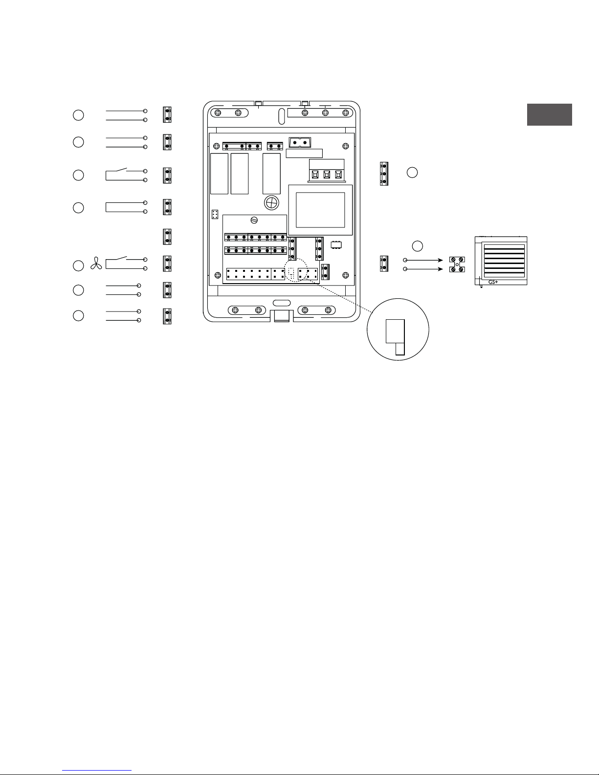
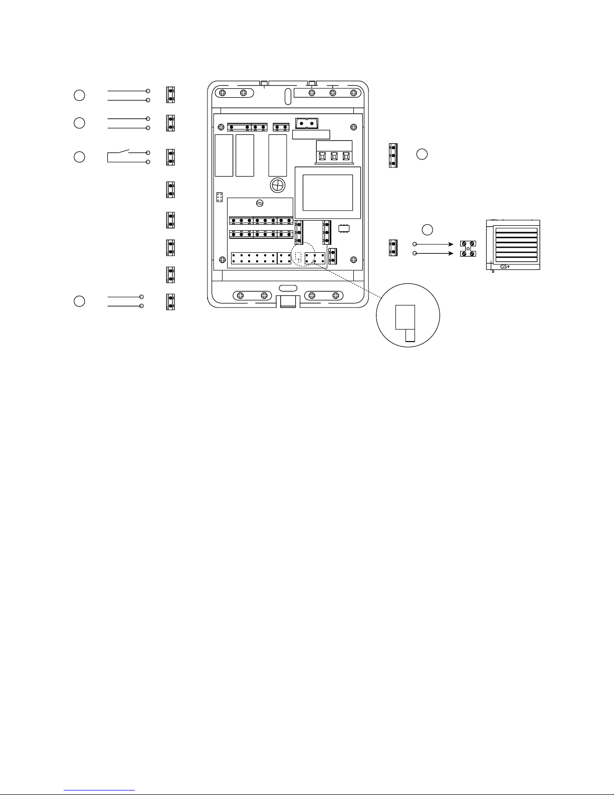
4.1 Connection 0-10 VDC burner capacity control for G(S)+
Interface+ module
A - Power supply 1~230V + N + PE / 50Hz
B - Connecting air heater with 2-wired bus cable.
Potential free entries
C - Ventilation
E - External override
F - Reset
Potential free exits
G - Malfunction (NO) 230V or 24V*
H - Operation (NO) 230V or 24V*
Analog input
D - Burner capacity input 0-10 VDC
Communication
I - RS 485 Modbus
* Only 1 voltage may be used: 230V or 24V.
** The switch must always be switched to the right.
H
G
F
E
C
D
I
A
B
17
20
L
N
PE
27
28
26
25
12
11
8
7
6
5
4
3
9
10
15
16
3
4
25 26 27 28 29
30
LNPE
135791113 15
2
468101214 16
17
18
19
20
21
22
24
23
-
+
A-
B+
S4(ON)
S4(ON)**
Page 8
4.2 Connection burner capacity with Modbus for G(S)+
Interface+ module
A - Power supply 1~230V + N + PE / 50Hz
B - Connecting air heater with 2-wired bus cable.
Potential free entries
F - Reset
Potential free exits
G - Malfunction (NO) 230V or 24V*
H - Operation (NO) 230V or 24V*
Communication
I - RS 485 Modbus
* Only 1 voltage may be used: 230V or 24V.
** The switch must always be switched to the right.
8
H
G
F
A
B
17
20
L
N
PE
27
28
26
25
12
11
8
7
6
5
4
3
3
4
25 26 27 28 29
30
LNPE
135791113 15
2
468101214 16
17
18
19
20
21
22
24
23
I
9
10
15
16
A-
B+
S4(ON)
S4(ON)**
Page 9
9
EN
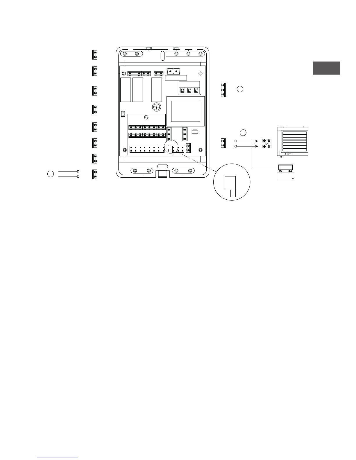
4.3 Connection reading and modifying Optitherm+ with Modbus for G(S)+/GSX
Interface+ module
A - Power supply 1~230V + N + PE / 50Hz
B - Connecting air heater with 2-wired bus cable.
For connecting more than 1 air heaters see gures [2] [3]
Communication
I - RS 485 Modbus
* Only 1 voltage may be used: 230V or 24V.
** The switch must always be switched to the right.
Note: It may happen that both contacts, malfunction and operation, are present simultaneously.
A
B
17
20
L
N
PE
27
28
26
25
12
11
8
7
6
5
4
3
3
4
25 26 27 28 29
30
LNPE
135791113 15
2
468101214 16
17
18
19
20
21
22
24
23
I
9
10
15
16
A-
B+
06 29 189
OptiTherm+
06 29 189
S4(ON)
S4(ON)**
Page 10
10
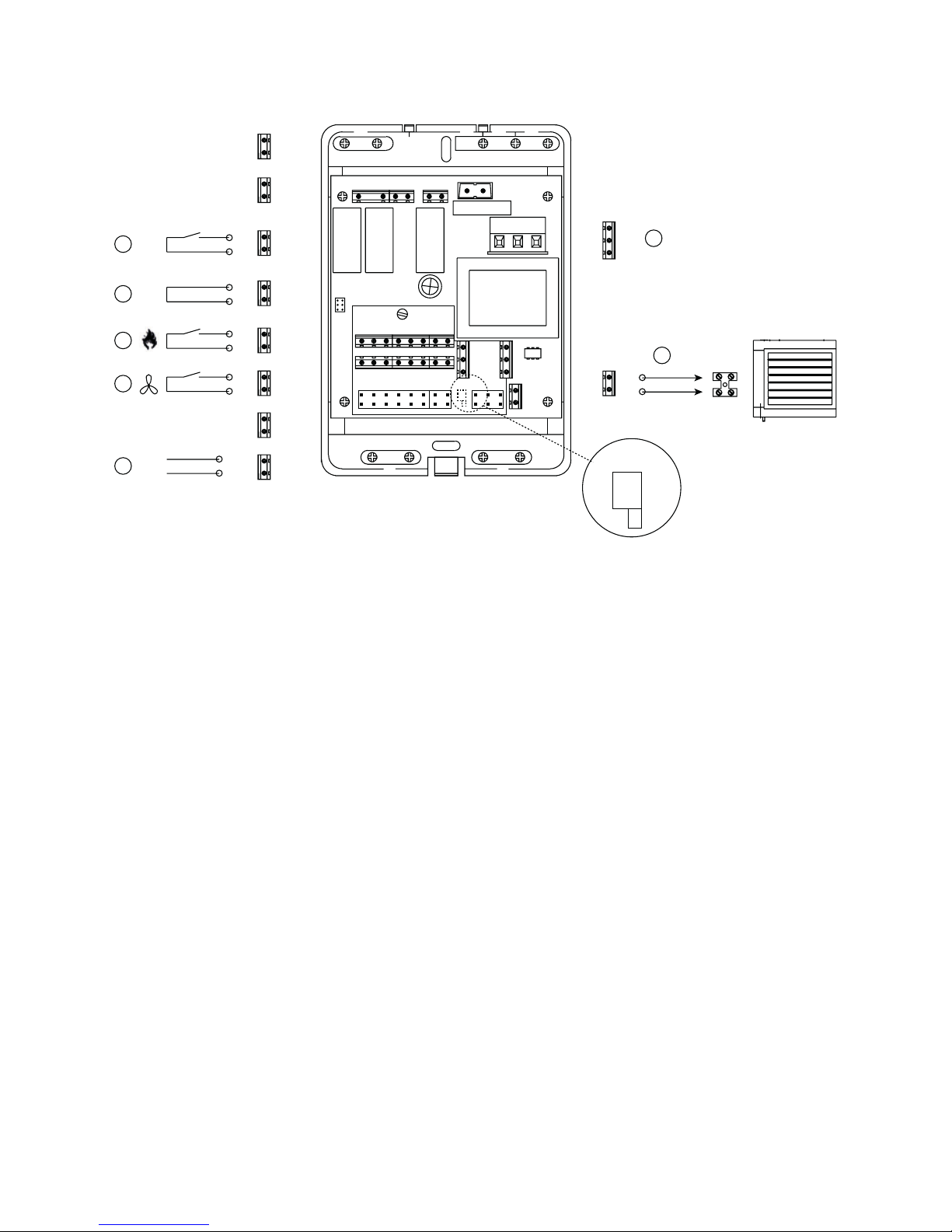
4.4 Connection control GSX units with hard contacts from an external controller
Interface+ module
A - Power supply 1~230V + N + PE / 50Hz
B - Connecting air heater with 2-wired bus cable.
For connecting more than 1 air heaters see gures [5] [7]
Potential free entries
C - Ventilate
E - External override
F - Reset
J - Heating
Communication
I - RS 485 Modbus
* Only 1 voltage may be used: 230V or 24V.
** The switch must always be switched to the right.
Note: It may happen that both contacts, malfunction and operation, are present simultaneously.
A
B
17
20
L
N
PE
27
28
26
25
12
11
8
7
6
5
4
3
3
4
25 26 27 28 29
30
LNPE
135791113 15
2
468101214 16
17
18
19
20
21
22
24
23
I
9
10
15
16
A-
B+
F
E
J
C
GSX
S4(ON)
S4(ON)**
Page 11
11
5.0 General Modbus information [8]
Conguration
Protocol Modbus RTU
Default slave adress 01 *
Baud rate 9600 bps
Data length 8
Parity None
Stop bits 1
Physical layer RS485 (two wire + GND advised)
* Factory setting, other value on request.
5.1 Release for writing
To write in the Holding register, a “1” should be written in Holding register 99. A Modbus command
must then be written within 4 seconds. After 4 seconds, Holding register 99 will be set to “0” again.
5.2 Reading holding registers
The holding registers are divided into groups:
Group 1 Holding registers 100 – 199
Group 2 Holding registers 200 – 299
Group 3 Holding registers 300 – 399
The registers must be read per group. Example wrong reading: 98 - 120
EN
Page 12

Explanation Holding Register 102, 300, 310...370
STATUS Number Description
RESET_0 0 Reset
RESET_1 1 Reset
STANDBY_0 2 Stand-by
PRE_PURGE 3 Pre-purge
PRE_PURGE-1 4 Pre-purge
SAFETY_ON 5 Internal test
SAFETY_OFF 6 Internal test
IGNIT_0 7 Ignition
IGNIT_1 8 Ignition
BURN_0 9 In operation
SHUT_DOWN_RELAYS_
TEST_0
10 Hardware check
SHUT_DOWN_RELAYS_
TEST_1
11 Hardware check
POST_PURGE_0 12 After ventilation
POST_PURGE_1 13 After ventilation
PUMP_CH_0 14 - No meaning PUMP_CH_1 15 - No meaning PUMP_HW_0 16 - No meaning PUMP_HW_1 17 - No meaning ALARM_1 18 Malfunction
ERROR_CHECK 19 Block
BURNER_BOOT 20 Burner restart
CLEAR_E2PROM_ERROR 21 Clean up internal error table
STORE_BLOCK_ERROR 22 Save blocking error code
WAIT_A_SECOND 23 Restart after blocking
12
Page 13

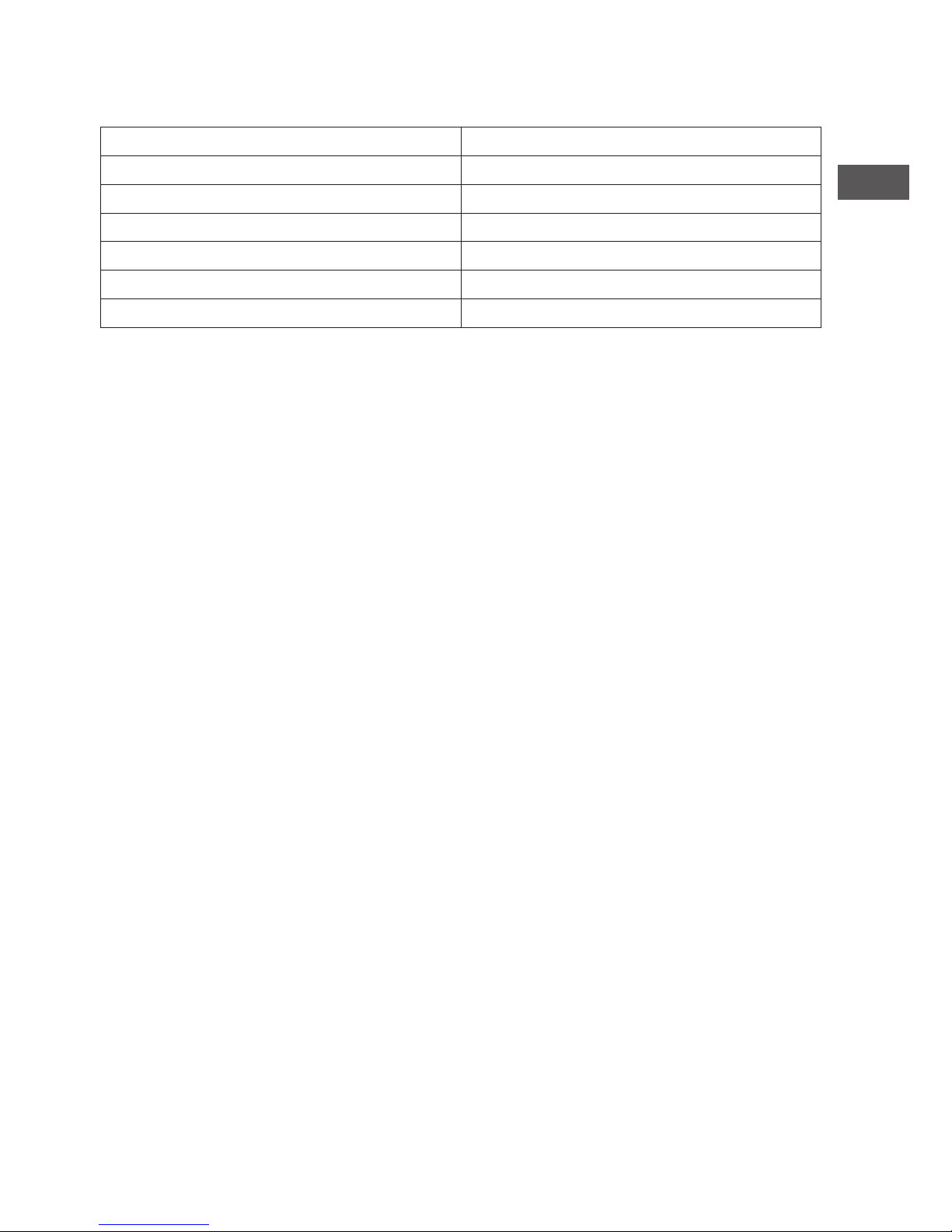
6.0 Fault codes
Explanation Holding Register 104, 302, 312...372
Code Error Description
01 Ignition failure Ignition has failed (three attempts at ignition).
02
Gas valve relay/T max. Maximum thermostat is open
03 Gas valve
Gas valve faulty / Wire connecting the gas valve to the
burner control box is open-circuit or has been incorrectly
connected.
10 Sensor diff too high
Temperature difference between both outlet temperature
sensors is too high.
23 Filters/system fan Filter is dirty/system fan has suffered a thermal failure
25 T max. Maximum thermostat is open
31
Too many attempts to restart Flame goes out (3x) when the device is in operation.
42 Choke relay broken Relay of the choke valve is broken
43 Combustion air fan failure
The current speed of the combustion air fan deviates too
much
62
Block drain Condensate drain blocked. Condensate pump failure.
65 Phase and zero back to front Phase and zero not connected correctly
72
Air out sensor open Outlet temperature sensor interrupted
73 Unit temp sensor open Ambient temperature sensor interrupted
78 Air out safety open Outlet temperature sensor interrupted
80 Air out shorted Outlet temperature sensor has short circuited
81 Unit temp shorted Ambient temperature sensor has short circuited
86 Air out safety shorted Outlet temperature sensor has short circuited
When a different error code displayed on the thermostat appears, press the Reset button. If the fault returns,
please contact the vendor of the device.
Note!
Please refer also to the technical documentation for the air heater for information on the above faults,
causes and solutions.
7.0 Disposal of Interface+ module
When the Interface+ module is being replaced or removed it must be recycled or destroyed in
accordance with national and/or local regulations.
13
EN
Page 14

14
Page 15

15
Lesen Sie dieses Dokument sorgfältig
durch, bevor Sie das Gerät installieren
Warnhinweis
Fehlerhaft durchgeführte Installationen, Einstellungen, Änderungen, Reparaturen oder
Wartungsmaßnahmen können zu Sachschäden und Verletzungen führen. Alle Arbeiten
müssen von geprüften, qualizierten Fachleuten durchgeführt werden. Falls das Gerät nicht
vorschriftsgemäß aufgestellt wird, erlischt die Garantie.
Dieses Gerät ist nicht für den Gebrauch durch Personen (einschließlich Kindern) mit
verminderter körperlicher, Sinnes- oder geistiger Leistungsfähigkeit, mangelnder Erfahrung und
mangelnder Kenntnissen bestimmt, sofern sie nicht unter Aufsicht stehen oder durch eine Person,
die für Ihre Sicherheit verantwortlich ist, im Gebrauch des Gerätes angeleitet werden. Kinder
müssen vom Gerät ferngehalten werden.
Wenn in der Anleitung auf eine Abbildung oder Tabelle verwiesen wird, wird eine Zahl in eckigen
Klammern angegeben, beispielsweise [3]. Die Zahl verweist auf die Abbildungen und Tabellen mit
der entsprechenden Nummer am Ende der Anleitung.
1.0 Allgemeines
1.1 Änderungen vorbehalten
Der Hersteller strebt eine kontinuierliche Verbesserung der Produkte an und behält sich das Recht
vor, ohne vorherige Mitteilung Änderungen an technischen Daten vorzunehmen. Die technischen
Angaben werden als korrekt angenommen, bilden aber keine Grundlage für einen Vertrag oder
Gewährleistungsansprüche. Alle Bestellungen werden gemäß den Standardkonditionen in unseren
AGB’s (auf Anfrage erhältlich) angenommen.
1.2 Allgemeine Warnhinweise
Die Installation muss den geltenden landesweiten und örtlichen Bestimmungen entsprechen.
Daher darf das Gerät nur von einem sachkundigen und qualizierten Installateur unter Beachtung
der nationalen und internationalen Vorschriften installiert werden. Im Falle einer unsachgemäßen
Installation, Einstellung, Änderung, Wartung oder Instandsetzung erlischt die Gewährleistung.
DE
Page 16

16
1.3 Produktbeschreibung und Anwendung
Das Interface+ Modul kann in folgenden Kombinationen verwendet werden:
1.3.1 0-10 VDC Reglung der Brennerleistung
Verbindung: ein G(S)+ pro Interface+ Modul.
Von einem externen Regler wird die Brennerleistung mit Hilfe eines 0 – 10 VDC Signals gesteuert.
Funktionen:
• Brennerleistungsregelung: Signal 0-10 VDC, Steuerung 0 - 9 VDC <0,9 V Brenner aus, > 1,5 V
Brenner startet.
• Lüften Sie kontinuierlich
• Reset / zurücksetzen
• Anzeige (potentialfreier Kontakt) *
• Störung (potentialfreier Kontakt) *
• Auslesen aktueller Daten mit Hilfe des Protokolls
Siehe Anschlussdiagramm 4.1 für die spezischen Verbindungen dieser Anwendung.
* Für beide Ausgänge darf nur 1 Spannung von 230V oder 24V verwendet werden.
1.3.2 Brennerkapazität Kontrolle
Verbindung: ein G(S)+ pro Interface+ Modul.
Die Brennerleistung wird von einem externen Regler geregelt.
Funktionen:
• Brennerleistungsreglung (0-10 VDC anzeigen 0-1000, Reglung 0-900)
• Lüften Sie kontinuierlich
• Reset über den Kontakt auf der Schnittstelle, (nicht mit Modbus)
• Auslesen aktueller Daten mittels Modbus
Siehe Anschlussdiagramm 4.2 für die spezischen Verbindungen dieser Anwendung.
Erklärung der spezischen Modbus-Halteregister für diese Anwendung:
Code Zugang Beschreibung Range
121 R Aktuelle Brennerleistung 0-900
122 R + W Brennerleistung Regelung 0-900
133* R + W CH-Modus 7 .. 8
204 R + W Externe Überbrückung 0 = keine Überbrückung
1 = Überbrückung aktiv
205** R + W Fan Override 0 = aus
1 = durchlaufenden Ventilatoren
* bei dieser Anwendung muss der der CH Modus auf 8 eingestellt werden
** Durchlaufende Ventilatoren sind nur möglich, wenn die externe Überbrückung aktiv ist.
Code 100 - 133 sind in dieser Anwendung.
Page 17

17
DE
1.3.3 Auslesen der G(S)+-Geräte, ändern der Einstellungen des Optitherm+
Verbindung: maximal 8 G(S)+ Geräte, Optitherm+ und Interface+ Modul.
Den aktuellen Status der Geräte, kann mit Hilfe des Modbus ausgelesen werden. Zusätzlich
können die Sollwerte des Optitherm + geändert, und das Uhrprogramm außer Kraft gesetzt
werden. Das Zurücksetzen der Geräte ist mit dem Optitherm + möglich. Ein digitaler Sensor kann
die Raumtemperatur ermitteln, auf deren Basis es gesteuert wird. Optitherm + kann in einem
zusätzlichen Raum platziert werden (siehe Optitherm + Anleitung zur Sensorauswahl).
Siehe Tabelle 4.3 Lesen und Ändern der Verbindung Optitherm + mit dem Modbus
Erklärung der spezischen Modbus-Halteregister für diese Anwendung:
Code Zugang Beschreibung Range
201* R + W Überbrückung des Heizmodus 0= Uhrprogramm Optitherm+
aktiv
1= aus
Kontinuierlich:
2= Frost
3= Nacht
4= ECO
5= Tag
202 R + W Belüftungsmodus 0 = aus
1 = System Ventilatoren drehen
kontinuierlich
220 R + W Tages Solltemperatur [°C] (Faktor 100)
221 R + W Eco Sollwert Temperatur [°C] (Faktor 100)
222 R + W Nacht Sollwert Temperatur [°C] (Faktor 100)
223 R + W Frost [°C] (Faktor 100)
133** R + W CH Modus 7 .. 8
* Wenn Sie nach einer Überbrückung (1 - 5) zum Optitherm + zurückkehren möchten muss
eine 0 gesetzt werden. Das Ändern ist im Optitherm+ Menü nicht möglich.
** In dieser Anwendung muss der CH-Modus auf 7 eingestellt sein (Standardeinstellung)
*** Die Halteregister 122, 204 und 205 funktionieren in dieser Anwendung nicht.
1.3.4 Steuerung mit Kontakten (nur für GSX-Geräte)
Verbindung: bis zu 8 GSX-Geräte und Interface+
Mit einem Interface + Modul können ein oder mehrere GSX-Geräte mit einem Gebäudetechnik
System gesteuert werden. Alle Kontakte sind potentialfrei. Die angeschlossenen GSX-Geräte
werden gleichzeitig über folgende Signale gesteuert: Heizen, Lüften und / oder Reset. Wenn ein
Warmlufterzeuger defekt ist oder in Betrieb ist, erfolgt eine Meldung durch einen potentialfreien
Kontakt. Der aktuelle Status der Geräte kann mit Modbus gelesen werden.
Siehe Anschlussdiagramm 4.4 für die spezischen Verbindungen dieser Anwendung.
Page 18
18
2.0 Technische Daten
• Typbezeichnung : Interface+ Modul
• Typ Thermostat : Modul für die Kommunikation mit beispielsweise einem
Gebäudemanagementsystem
• Artikelnummer : 06 29 188
• Anschluss : Interface+ Modul g Lufterhitzer Bus System (2-aderig)
Interface+ Modul g externe Verbindung z.B.
Gebäudemanagement 230V oder 24V (für beide potentialfreie
Ausgänge darf nur eine Spannung verwendet werden: 230V oder
24V).
Interface+ Modul g externer Regler 0-10V
Interface+ Modul g 0-10V externe Verbindung
GLT Gebäudeleittechnik: Modbus
• Verkabelung : Interface Modul -> Lufterhitzer abgeschirmtes BUS-Kabel,
siehe auch §3.0
• Abmessungen : 109 x 154 x 49mm (LxBxH)
• Gewicht : 498 Gramm
• Schutzklasse : IP20
• Umgebungstemperatur : 0-40°C
3.0 Verkabelung
Für die Verkabelung zwischen dem Interface Modul und Lufterhitzer muss immer ein abgeschirmtes
BUS-Kabel verwendet werden. Die maximale Länge und dem richtigen Durchmesser entnehmen Sie
bitte Tabelle [1].
Aufgepasst!
Die Abschirmung des Kabels muss an der Seite der Lufterhitzer angeschlossen werden.
Das BUS-Kabel muss entsprechend der länderspezischen Ausführung gewählt werden, wobei die
Werte der technischen Daten einzuhalten sind.
Geeignete Busleitungen:
Kabel Typ Anwendung EIB-Spezikation
YCYM Festinstallation Trockene, feuchten, nassen
Räumen. An der frischen
Luft (keine direkte Sonneneinstrahlung). Aufbau, Installation, in Rohrleitungen.
J-Y(st)Y Festinstallation Nur in Innenräumen. Aufbau, in
Rohrleitungen.
JH(st)H Halogenfreie Kabel,
Remote - Installation.
A-2Y(L)2Y
A-2YF(L)2Y
Telefonleitung, Installation in
den Außenbezirken.
Page 19

19
DE
4.0 Anschlüsse
4.1 Anschluss 0-10 VDC Brennerleistungsreglung für G(S)+
Interface+ Modul
A - Netzteil 1~230V + N + PE / 50Hz
B - Anschluss für Luftheizung durch BUS 2 Draht
Potenzialfreie Eingänge
C - Lüften
E - externe Übersetuerung
F - Reset
Potenzialfreie Ausgänge
G - Störung (NO) 230V oder 24V*
H - Betriebsmeldung (NO) 230V oder 24V*
Analoge Eingänge
D - Brennerleistung 0-10 VDC
Kommunikation
I - RS 485 Modbus
* Es darf nur eine Spannungsart verwendet werden: 230V oder 24V.
** Der Schalter muss immer in der rechten Position stehen.
H
G
F
E
C
D
I
A
B
17
20
L
N
PE
27
28
26
25
12
11
8
7
6
5
4
3
9
10
15
16
3
4
25 26 27 28 29
30
LNPE
135791113 15
2
468101214 16
17
18
19
20
21
22
24
23
-
+
A-
B+
S4(ON)
S4(ON)**
Page 20

4.2 Anschluss Brennerleistung mit Modbus für G(S)+
Interface+ Modul
A - Netzteil 1~230V + N + PE / 50Hz
B - Anschluss für Luftheizung durch BUS 2 Draht
Potenzialfreie Eingänge
F - Reset
Potenzialfreie Ausgänge
G - Störung (NO) 230V oder 24V*
H - Betriebsmeldung (NO) 230V oder 24V*
Kommunikation
I - RS 485 Modbus
* Es darf nur eine Spannungsart verwendet werden: 230V oder 24V.
** Der Schalter muss immer in der rechten Position stehen.
20
H
G
F
A
B
17
20
L
N
PE
27
28
26
25
12
11
8
7
6
5
4
3
3
4
25 26 27 28 29
30
LNPE
135791113 15
2
468101214 16
17
18
19
20
21
22
24
23
I
9
10
15
16
A-
B+
S4(ON)
S4(ON)**
Page 21

21
DE
4.3 Lesen und Ändern der Verbindung Optitherm+ mit dem Modbus für G(S)+/GSX
Interface+ Modul
A - Netzteil 1~230V + N + PE / 50Hz
B - Anschluss für Luftheizung durch BUS 2 Draht
Für den Anschluss mehrerer Geräte siehe auch Abbildung [2] [3]
Kommunikation
I - RS 485 Modbus
* Es darf nur eine Spannungsart verwendet werden: 230V oder 24V.
** Der Schalter muss immer in der rechten Position stehen.
Bemerkung: es kann passieren, dass beide Kontakte, „Störung“ und „in Betrieb“, gleichzeitig
angezeigt werden.
A
B
17
20
L
N
PE
27
28
26
25
12
11
8
7
6
5
4
3
3
4
25 26 27 28 29
30
LNPE
135791113 15
2
468101214 16
17
18
19
20
21
22
24
23
I
9
10
15
16
A-
B+
06 29 189
OptiTherm+
06 29 189
S4(ON)
S4(ON)**
Page 22

22
4.4 Anschluss der GSX-Steuergeräte mit Kontakten von einem externen Regler
Interface+ Modul
A - Netzteil 1~230V + N + PE / 50Hz
B - Anschluss der Warmlufterzeuger über BUS 2 Draht
Zum Anschluss mehrerer Geräte (max. 8) siehe auch Abb. [5] [7]
Potenzialfreie Eingänge
C - Lüften
E - externe Übersteuerung
F - Reset
J - Heizung
Kommunikation
I - RS 485 Modbus
* Es darf nut eine Spannungsart verwendet werden: 230V oder 24V.
** Der Schalter muss immer in der rechten Position stehen.
Bemerkung: es kann passieren, dass beide Kontakte “Störung” und “Betrieb” gleichzeitig
angezeigt werden.
A
B
17
20
L
N
PE
27
28
26
25
12
11
8
7
6
5
4
3
3
4
25 26 27 28 29
30
LNPE
135791113 15
2
468101214 16
17
18
19
20
21
22
24
23
I
9
10
15
16
A-
B+
F
E
J
C
GSX
S4(ON)
S4(ON)**
Page 23

23
5.0 Allgemeine Modbus Informationen [8]
Konguration
Protokoll Modbus RTU
Default slave adress 01 *
Baud rate 9600 bps
Data length 8
Parity Keine
Stop bits 1
Physical layer RS485 (two wire + GND advised)
* Werkseinstellung, andere Werte auf Anfrage verfügbar.
5.1 Freigabe zum Schreiben
Um im Holding-Register zu schreiben, muss im Holding-Register 99 eine “1” geschrieben werden.
Im Modbus-Befehl muss innerhalb von 4 Sekunden geschrieben werden. Nach 4 Sekunden wird das
Halteregister 99 auf “0” zurückgesetzt
5.2 Holding-Register
Die Holding-Register sind in Gruppen unterteil:
Gruppe 1 Holding registers 100 – 199
Gruppe 2 Holding registers 200 – 299
Gruppe 3 Holding registers 300 – 399
Das Register muss pro Gruppe gelesen werden. Bsp. Falsch gelesen: 98-120
DE
Page 24

Erklärung Holding-Register 102, 300, 310…370
STATUS Number Description
RESET_0 0 Reset
RESET_1 1 Reset
STANDBY_0 2 Stand-by
PRE_PURGE 3 Pre-purge
PRE_PURGE-1 4 Pre-purge
SAFETY_ON 5 Internal test
SAFETY_OFF 6 Internal test
IGNIT_0 7 Ignition
IGNIT_1 8 Ignition
BURN_0 9 In operation
SHUT_DOWN_RELAYS_
TEST_0
10 Hardware check
SHUT_DOWN_RELAYS_
TEST_1
11 Hardware check
POST_PURGE_0 12 After ventilation
POST_PURGE_1 13 After ventilation
PUMP_CH_0 14 - No meaning PUMP_CH_1 15 - No meaning PUMP_HW_0 16 - No meaning PUMP_HW_1 17 - No meaning ALARM_1 18 Malfunction
ERROR_CHECK 19 Block
BURNER_BOOT 20 Burner restart
CLEAR_E2PROM_ERROR 21 Clean up internal error table
STORE_BLOCK_ERROR 22 Save blocking error code
WAIT_A_SECOND 23 Restart after blocking
24
Page 25

6.0 Fehlercode
Erklärung Holding Register 104, 302, 312…372
Code Bedeutung Ursache
01 Zündfehler Keine gute Zündung (drei Zündversuche)
02
Gasventil Relais /T max. Überhitzungsthermostat ist geöffnet
03 Gasventil
Gasventil defekt / Verbindung zwischen Gasventil und
Brennerautomat unterbrochen oder nicht ordnungsgemäß
angeschlossen
10 Sensor Diff. Zu groß
Der Temperaturunterschied zwischen den beiden Ausblassensoren ist zu groß.
23 Filter /Systemlüfter
Filter ist verschmutzt / Systemlüfter ist thermisch
ausgeschaltet.
25 T Max. Überhitzungsthermostat ist geöffnet.
31
Zu viele Flammenausfälle Flamme erlischt (3x), wenn das Gerät in Betrieb ist.
42 Starterrelais defekt Relais Bsp. Bypass Gasmagnetventil ist defekt.
43 Fehler Ventilator Drehzahl Verbrennungsluftventilator weicht zu viel ab.
62
Kondensat blockiert
Kondensatablauf blockiert oder defekt, optional
Kondensatpumpe
65 Phase und Null vertauscht Phase und Null falsch angeschlossen
72
Interner Fehler Ausblastemperaturfühler unterbrochen
73 Interner Fehler Umgebungstemperatursensor unterbrochen
78 Interner Fehler Ausblastemperaturfühler unterbrochen
80 Ausblasssensor aus Ausblastemperaturfühler kurzgeschlossen
81 Gerät ausgeschaltet Umgebungstemperatursensor kurzgeschlossen
86 Interner Fehler Ausblastemperaturfühler kurzgeschlossen
Wenn ein anderer Fehlercode auf dem Thermostat angezeigt wird, drücken Sie die Reset Taste. Wenn der
Fehlercode dann wieder erscheint, wenden Sie sich bitte an den Hersteller des Gerätes.
Bemerkungen
Bitte beachten Sie hinsichtlich Informationen über die vorgenannten Fehler, Ursachen und Lösungen,
auch die technische Dokumentation des Luftheizgerätes.
7.0 Entsorgung
Wenn das Interface+ Modul ausgetauscht oder entfernt wird, muss es gemäß den nationalen und/oder
lokalen Vorschriften der Wiederverwertung zugeführt oder vernichtet werden.
25
DE
Page 26

26
Page 27

27
Lisez complètement ce document
avant de commencer l’installation
et la mise en service
Avertissement!
Une installation, un réglage, une modication, une réparation ou un entretien mal exécuté(e)
peut entraîner des dommages matériels ou des blessures. Tous les travaux doivent être exécutés
par des professionnels reconnus et qualiés. Si l’appareil n’est pas installé en respectant les
prescriptions, la garantie échoit. Cet appareil n’est pas conçu pour être utilisé par des personnes
(y compris des enfants) présentant des capacités physiques, mentales ou sensorielles réduites
ou manquant d’expérience et de connaissances, sauf s’ils sont surveillés ou sont informés sur
l’utilisation de l’appareil par une personne responsable de leur sécurité. Les enfants doivent être
surveillés pour s’assurer qu’ils ne jouent pas avec l’appareil.
Si ce manuel technique renvoie vers une illustration ou un tableau, alors vous verrez un chiffre entre
des crochets, par exemple [3]. Le numéro renvoie vers les illustrations et les tableaux se trouvant
dans ce manuel technique avec le numéro mentionné.
1.0 Généralités
1.1 Sousréservedemodications
Le fabricant s’engage dans l’amélioration continue de ses produits et se réserve le droit d’apporter
des modications dans les spécications, sans avis préalable. Les détails techniques sont supposés
être corrects mais ne constituent pas la base d’un contrat ou d’une garantie. Toutes les commandes
sont acceptées moyennant le respect de nos conditions générales de vente et de livraison
(disponibles sur demande).
1.2 Avertissements généraux
L’installation doit répondre aux prescriptions nationales et/ou régionales en vigueur. Faites dès
lors installer le module Interface+ par un installateur compétent et qualié en tenant compte de la
législation nationale et internationale. En cas d’installation, de réglage, de modication, d’entretien ou
de réparation erroné, la garantie échoit.
FR
Page 28

28
1.3 Description du produit et application
Le module Interface+ peut être utilisé dans les combinaisons suivantes:
1.3.1 0 – 10VDC contrôle de la capacité du brûleur
Raccordement: un G(S+) par Interface+.
Via un contrôleur externe, la capacité du brûleur est vériée avec un signal 0 - 10 VDC.
Fonctions:
• Contrôle de la capacité du brûleur: Signal 0-10Vdc, Règlement 0 - 9 Vdc < 0.9V brûleur éteint,
> 1,5V brûleur allumé
• Contact aération en continu
• Réinitialisation
• Notication d’opération (Contact sans potentiel)*
• Signal défaut (Contact sans potentiel)*
• Lecture des données actuelles en utilisant Modbus.
Voir le schéma de connexion 4.1 pour les connexions spéciques à cette application.
* Seule une tension de 230V ou 24V peut être utilisée pour les deux sorties sans potentiel.
1.3.2 Contrôle de la capacité du brûleur par rapport à Modbus
Raccordement: un G(S+) par Interface+.
La capacité du brûleur est contrôlée à partir d’un contrôleur externe en utilisant Modbus.
Fonctions:
• Contrôle de la puissance du brûleur (0-10Vdc afché 0-1000, réglage 0-900)
• Ventilation continue
• Réinitialiser via le contact sur l’interface + (pas avec Modbus)
• Lecture des données actuelles en utilisant Modbus.
Voir le schéma de connexion 4.2 pour les connexions spéciques pour cette application.
Explication des registres de maintien Modbus spéciques pour cette application:
Registre
d’exploitation
Accès Description Range
121 R Capacité actuelle du
brûleur
0-900
122 R + W Capacité du brûleur réglage 0-900
133* R + W CH mode 7 .. 8
204 R + W Commande externe 0 = pas de override
1 = commande activée
205** R + W Commande du ventilateur 0 = off
1 = ventilateur du système continu
* Dans cette application, le mode CH doit être réglé sur 8
** Le ventilateur continu n’est possible que si la commande externe est active (204 = 1).
Les registres de maintien 100 - 133 sont inclus dans cette application.
Page 29

29
FR
1.3.3 LecturedespériphériquesG(S)+etmodicationdesparamètresouremplacementde
l’Optitherm+
Connexion: jusqu’à 8 G(S)+ appareils, Optitherm+ et Interface+
L’état actuel des appareils peut être lu à l’aide de Modbus. De plus, les points de consigne de
l’Optitherm+ peuvent être modiés et le programme d’horloge peut être annulé. La réinitialisation
des appareils est possible en utilisant d’Optitherm+. En option, la température ambiante actuelle
peut être déterminée à l’aide d’un capteur numérique en se basant sur la température à laquelle elle
est réglée. Optitherm+ peut ensuite être placé dans une pièce supplémentaire (voir Optitherm+
pour la sélection du capteur).
Voir le schéma de connexion 4.3 pour les connexions spéciques à cette application.
Explication des registres de maintien Modbus spéciques pour cette application:
Registre
d’exploitation
Accès Description Range
201* R + W Surchauffe en mode chauffage 0= programme d’horloge
Optitherm + actif
1= off
2= Continu gel
3= Continu nuit
4= Continu Eco
5= Continu jour
202 R + W Mode de ventilation 0 = off
1 = le système du ventilateur
fonctionne en continu
220 R + W Point de réglage temperature
Jour
[°C] (facteur 100)
221 R + W Point de réglage temperature
Eco
[°C] (facteur 100)
222 R + W Point de réglage temperature
Nuit
[°C] (facteur 100)
223 R + W Frost [°C] (facteur 100)
133** R + W CH mode 7 .. 8
* Si après une commande (1 - 5) vous voulez revenir au programme d’horloge de
l’Optitherm+, vous devez écrire 0. Le changement n’est pas possible dans le menu
Optitherm+.
** Dans cette application, le mode CH doit être réglé sur 7 (réglage par défaut).
*** Les registres de maintien 122, 204 et 205 ne fonctionnent pas dans cette application.
1.3.4 Contrôle avec contacts (uniquement pour les appareils GSX)
Connexion: jusqu’à 8 G(S)+ appareils et Interface+
Avec une interface + un ou plusieurs appareils GSX, avec un maximum de 8, peuvent être
commandés à partir, par exemple, d’un système de gestion de bâtiment. Tous les contacts sont
sans potentiel. Les appareils GSX connectés sont commandés simultanément par les signaux
suivants: chauffage, ventilation et / ou réinitialisation. Si un réchauffeur d’air fonctionne mal ou est en
Page 30

30
fonctionnement, une notication est envoyée au moyen d’un contact sans potentiel. L’état actuel des
appareils peut être lu à l’aide de Modbus.
Voir le schéma de connexion 4.4 pour les connexions spéciques à cette application.
2.0 Caractéristiques techniques
• Classication de l’unité : Module Interface+
• Type de thermostat : Module pour communication avec p.ex.
système de gestion de bâtiment.
• Numéro d’article : 06 29 188
• Raccordement : Interface+ module g système BUS aérotherme, (2 ls)
câble BUS.
Interface+ module g raccordement externe, p.ex. gestion
bâtiment 230V ou 24V (pour les 2 contacts libre potentiel, seul 1
tension à appliquer 230V ou 24V).
Interface+ module g contrôleur externe 0-10V
Interface+ module g 0-10V raccordement externe, p.ex.
gestion bâtiment: Modbus
• Câblage : Interface+ module g aérothermes.
câble BUS protégé, zie ook §3.0
• Dimensions : 109 x 154 x 49mm (Lxlxh)
• Poids : 498 grammes
• Degré de protection : IP20
• Température d’ambiance : 0-40°C
3.0 Câblage
Pour le câblage, il convient toujours d’utiliser du câble de bus blindé. Pour la longueur maximale et le
diamètre adéquat, voir également le tableau [1].
Attention !
Raccorder l’armature du câble à la terre sur le réchauffeur d’air.
Le câble bus doit être choisi conformément à l’exécution spécique du pays, les valeurs mentionnées
dans les données techniques doivent être conservées.
Câbles de bus appropriés:
Type de câble Application Spécication EIB
YCYM Installation xe Zones sèches, humides, mouillées.
A l’air libre (par de rayon direct du soleil).
Construction, intégration, dans les conduites.
J-Y(st)Y Installation xe Uniquement dans les zones intérieures.
Construction, intégration, dans les conduites.
JH(st)H Conduites sans halogène,
installation à distance
A-2Y(L)2Y
A-2YF(L)2Y
Conduite souterraine du
téléphone ,Installation dans la
zone externe
Page 31

31
FR
4.0 Options de connexion
4.1 Connexion 0-10 VDC contrôle de la puissance du brûleur de G(S)+
Module Interface+
A - Alimentation 1~230V + N + PE / 50Hz
B - Connexion pour réchauffeur d’air au moyen d’un câble de bus 2 ls
Entrées sans potentiel
C - Ventilation
E - Commande externe
F - Réinitialisation
Sorties sans potentiel
G - Signal défaut (NO) 230V ou 24V*
H - Signal fonctionnement (NO) 230V ou 24V*
Entrée analogique
D - Capacité du brûleur input 0-10 VDC
Communication
I - RS 485 Modbus
* Une seule tension peut être utilisée de 230V ou 24V.
** Le commutateur doit toujours être positionné à la droite
H
G
F
E
C
D
I
A
B
17
20
L
N
PE
27
28
26
25
12
11
8
7
6
5
4
3
9
10
15
16
3
4
25 26 27 28 29
30
LNPE
135791113 15
2
468101214 16
17
18
19
20
21
22
24
23
-
+
A-
B+
S4(ON)
S4(ON)**
Page 32

4.2 Capacité de connexion du brûleur au moyen de Modbus de G(S)+
Module Interface+
A - Alimentation 1~230V + N + PE / 50Hz
B - Connexion pour réchauffeur d’air au moyen d’un câble de bus 2 ls
Entrées libre potentiel
F - Réinitialisation
Sorties sans potentiel
G - Signal défaut (NO) 230V ou 24V*
H - Signal fonctionnement (NO) 230V ou 24V*
Communication
I - RS 485 Modbus
* Une seule tension peut être utilisée de 230V ou 24V.
** Le commutateur doit toujours être positionné à la droite
32
H
G
F
A
B
17
20
L
N
PE
27
28
26
25
12
11
8
7
6
5
4
3
3
4
25 26 27 28 29
30
LNPE
135791113 15
2
468101214 16
17
18
19
20
21
22
24
23
I
9
10
15
16
A-
B+
S4(ON)
S4(ON)**
Page 33

33
FR
4.3 LireetmodierlaconnexionOptitherm+ModbusdeG(S)+/GSX
Module Interface+
A - Alimentation 1~230V + N + PE / 50Hz
B - Connexion pour réchauffeur d’air au moyen d’un câble de bus 2 ls
Pour connecter plusieurs appareils, voir aussi g. [2] [3]
Communication
I - RS 485 Modbus
* Une seule tension peut être utilisée de 230V ou 24V.
** Le commutateur doit toujours être positionné à la droite
Remarque: Il est possible que les deux contacts, le dysfonctionnement et le fonctionnement soient
présents simultanément.
A
B
17
20
L
N
PE
27
28
26
25
12
11
8
7
6
5
4
3
3
4
25 26 27 28 29
30
LNPE
135791113 15
2
468101214 16
17
18
19
20
21
22
24
23
I
9
10
15
16
A-
B+
06 29 189
OptiTherm+
06 29 189
S4(ON)
S4(ON)**
Page 34

34
4.4 Dispositifs GSX de contrôle de connexion avec contacts durs d’un contrôleur externe
Module Interface+
A - Alimentation 1~230V + N + PE / 50Hz
B - Connexion pour réchauffeur d’air au moyen d’un câble de bus 2 ls
Pour connecter plusieurs appareils, voir aussi g. [5] [7]
Entrées sans potentiel
C - Ventilation
E - Commande externe
F - Réinitalisation
J - Chauffage
Communication
I - RS 485 Modbus
* Une seule tension peut être utilisée de 230V ou 24V.
** Le commutateur doit toujours être positionné à la droite
Remarque: Il est possible que les deux contacts, le dysfonctionnement et le fonctionnement soient
présents simultanément.
A
B
17
20
L
N
PE
27
28
26
25
12
11
8
7
6
5
4
3
3
4
25 26 27 28 29
30
LNPE
135791113 15
2
468101214 16
17
18
19
20
21
22
24
23
I
9
10
15
16
A-
B+
F
E
J
C
GSX
S4(ON)
S4(ON)**
34
Page 35

35
5.0 Informations générales sur Modbus [8]
Conguration
Protocole Modbus RTU
Default slave adress 01 *
Débit en bauds 9600 bps
Longueur des données 8
Parité Aucune
Bits d’arrêt 1
Couches physiques RS485 (deux ls + GND conseillé)
* Réglage d’usine, autre valeur sur demande.
5.1 À l’écrit
Pour pouvoir écrire dans le registre de maintien, il est nécessaire d’écrire 99 “1” dans le registre de
maintien. Une commande Modbus doit y être écrite dans les 4 secondes. Après 4 secondes, le registre
de maintien 99 est remis à “0”.
5.2 Lire les registres de tenue
Les registres d’exploitation sont divisés en groupes:
Groupe 1 Registres d’exploitation 100 – 199
Groupe 2 Registres d’exploitation 200 – 299
Groupe 3 Registres d’exploitation 300 – 399
Les registres doivent être lus par groupe. Exemple de lecture incorrecte: 98 à 120.
35
FR
Page 36

36
Explication Registre d’exploitation 102, 300, 310...370
STATUS Numéro Description
RESET_0 0 Réinitialiser
RESET_1 1 Réinitialiser
STANDBY_0 2 Stand-by
PRE_PURGE 3 Pré-lavage
PRE_PURGE-1 4 Pré-lavage
SAFETY_ON 5 Test interne
SAFETY_OFF 6 Test interne
IGNIT_0 7 Allumage
IGNIT_1 8 Allumage
BURN_0 9 En fonctionnement
SHUT_DOWN_RELAYS_
TEST_0
10
Vérication du contrôle du
matériel
SHUT_DOWN_RELAYS_
TEST_1
11
Vérication du contrôle du
matériel
POST_PURGE_0 12 Après la ventilation
POST_PURGE_1 13 Après la ventilation
PUMP_CH_0 14 - Aucune signication PUMP_CH_1 15 - Aucune signication PUMP_HW_0 16 - Aucune signication PUMP_HW_1 17 - Aucune signication ALARM_1 18 Faute
ERROR_CHECK 19 Bloquer
BURNER_BOOT 20 Brûleur redémarré
CLEAR_E2PROM_ERROR 21
Nettoyer la table d’erreur
interne
STORE_BLOCK_ERROR 22
Enregistrer le code d’erreur de
blocage
WAIT_A_SECOND 23 Redémarrer après blocage
Page 37

37
6.0 Pannes
Explication Registre d’exploitation 104, 302, 312...372
Code Notication Cause
01 Erreur d’allumage Allumage incorrect (trois essais d’allumage).
02
Relais de valve à gaz / T max. Le thermostat maximum est ouvert
03 Vanne de gaz
La vanne de gaz est défectueuse / La connexion entre la
vanne de gaz et le brûleur est interrompue ou
incorrectement établie.
10 Sonde diff trop grand
Différence de température entre les 2 sondes de pulsion
trop grand
23 Filtres / ventilateur système
Le ltre est sale / arrêt thermique du ventilateur du
système
25 T max. Le thermostat maximum est ouvert
31
Trop de redémarrages La amme s’éteint (3x) pendant l’utilisation de l’appareil.
42 Choke relais defectueux Relais défectueux de la soupape vanne gaz
43 Erreur de vent. de combustion
Trop grande différence de la vitesse de rotation du ventila-
teur de combustion
62
Condensats blocque
Evacuation des condensats bloqués. Défaut pompe de
condensât
65 Phase et neutre inversés La phase et le neutre ont été inversés
72
Erreur sonde de pulsion Capteur de la température de l’air soufé interrompu
73 Erreur sonde de temp app Capteur de température ambiante interrompu
78 Erreur sonde de pulsion II Capteur de la température de l’air soufé interrompu
80 Erreur sonde de pulsion Capteur de la température de l’air soufé court-circuité
81 Erreur sonde de temp app Capteur de température ambiante court-circuité
86 Erreur sonde de pulsion II Capteur de la température de l’air soufé court-circuité
Quanduncoded’erreurdifférentafchésurlethermostatapparaît,appuyezsurleboutonReseten
premier. Si l’erreur revient, veuillez contacter le fournisseur de l’appareil.
Remarque !
Consultez également le manuel technique de l’aérotherme pour les pannes, causes et solutions
susmentionnées.
7.0 Disposition de Interface+ module
Quand le Interface+ module est remplacé ou éliminé, il doit être recyclé ou détruit conformément aux
règlementations nationales et/ou locales.
FR
Page 38

38
Page 39

39
Lees dit document door voordat u begint
met de installatie en ingebruikname
Waarschuwing!
Een foutief uitgevoerde installatie, afregeling, wijziging, reparatie of onderhoudsbeurt kan
leiden tot materiële schade of verwondingen. Alle werkzaamheden moeten door erkende,
gekwaliceerde vakmensen worden uitgevoerd. Indien het toestel niet volgens voorschrift wordt
geplaatst, vervalt de garantie. Dit apparaat is niet bedoeld voor gebruik door personen (inclusief
kinderen) met verminderde lichamelijke, zintuiglijke of geestelijke vermogens, of gebrek aan
ervaring en kennis, tenzij zij onder toezicht staan of worden geïnstrueerd over het gebruik van
het apparaat door een persoon die verantwoordelijk is voor hun veiligheid. Kinderen moeten
gecontroleerd worden om ervoor te zorgen dat ze niet met het apparaat spelen.
Indien in dit technisch boek wordt verwezen naar een afbeelding of tabel, dan wordt een getal tussen
vierkante haken vermeld, bijvoorbeeld [3]. Het nummer verwijst naar de afbeeldingen en tabellen
met het vermelde nummer achterin dit technisch boek.
1.0 Algemeen
1.1 Wijzigingen voorbehouden
De fabrikant streeft continu naar verbetering van haar producten, en behoudt zich het recht
voor om zonder voorafgaande kennisgeving veranderingen in de specicaties aan te brengen. De
technische details worden als correct verondersteld maar vormen geen basis voor een contract
of garantie. Alle orders worden geaccepteerd onder de standaard condities van onze algemene
verkoop- en leveringsvoorwaarden (op aanvraag leverbaar).
1.2 Algemene waarschuwingen
De installatie moet voldoen aan de geldende plaatselijke en/of landelijke voorschriften. Laat
daarom de Interface+ module door een vakbekwaam en gekwaliceerd installateur installeren met
inachtneming van de nationale en internationale regelgeving. Bij een foutieve installatie, afregeling,
wijziging, onderhoudsafhandeling of herstelling vervalt de garantie.
NL
Page 40

40
1.3 Productomschrijving en toepassing
De Interface+ module kan in de volgende combinaties toegepast worden:
1.3.1 0 – 10VDC brandercapaciteitregeling
Aansluiting: één G(S+) per Interface+.
Vanuit een externe regelaar wordt de brandercapaciteit geregeld met behulp van een 0 – 10Vdc
signaal.
Functies:
• Brandercapaciteit regeling: Signaal 0-10Vdc, Regeling 0 - 9 Vdc < 0.9V brander uit, > 1,5V
brander start.
• Contact continu ventileren
• Reset
• Bedrijfsmelding (potentiaal vrij contact)*
• Storing (potentiaal vrij contact)*
• Uitlezing actuele data met behulp van Modbus.
Zie het aansluitschema 4.1 voor de specieke aansluitingen voor deze toepassing.
* Voor beide potentiaalvrije uitgangen mag maar 1 spanning toegepast worden van 230V of 24V.
1.3.2 Brandercapaciteit regeling m.b.v. Modbus
Aansluiting: één G(S)+ per Interface+.
Vanuit een externe regelaar wordt de brandercapaciteit geregeld met behulp van Modbus.
Functies:
• Brandercapaciteit regeling (0-10Vdc weergegeven 0-1000, regeling 0-900)
• Continu ventileren
• Reset middels het contact op de Interface+ (niet m.b.v. Modbus)
• Uitlezing actuele gegevens m.b.v. Modbus.
Zie het aansluitschema 4.2 voor de specieke aansluitingen voor deze toepassing.
Toelichting op specieke Modbus holding registers voor deze toepassing:
Holding register Toegang Omschrijving Range
121 R Actuele brandercapaciteit 0-900
122 R + W Brandercapaciteit Regeling 0-900
133* R + W CH mode 7 .. 8
204 R + W Externe overbrugging 0 = geen overbrugging
1 = overbrugging actief
205** R + W Fan Override 0 = uit
1 = doorlopende syst. ventilator
* In deze toepassing moet CH mode ingesteld worden op 8
** Doorlopende ventilator is alleen mogelijk indien de externe overbrugging actief (204 = 1) is.
Holding registers 100 t/m 133 zijn hierin in deze toepassing.
Page 41

41
NL
1.3.3 Uitlezen van de G(S)+/GSX toestellen en wijzigen instellingen of overrulen van de Optitherm+
Aansluiting: maximaal 8 G(S)+/GSX toestellen, Optitherm+ en Interface+
Met behulp van Modbus kan de actuele status van de toestellen uitgelezen worden. Daarnaast
kunnen de setpoints van de Optitherm+ gewijzigd worden en kan het klokprogramma overruled
worden. Reset van de toestellen is mogelijk m.b.v. de Optitherm+. Optioneel kan m.b.v. een
digitale sensor de actuele ruimtetemperatuur bepaald worden, op basis waarvan geregeld wordt.
De Optitherm+ kan dan in een nevenruimte geplaatst worden (zie voor de sensor selectie de
handleiding van de Optitherm+).
Zie het aansluitschema 4.3 voor de specieke aansluitingen voor deze toepassing.
Toelichting op specieke Modbus holding registers voor deze toepassing:
Holding register Toegang Omschrijving Range
201* R + W Verwarming mode overbugging 0= klokprogramma Optitherm+
actief
1= off
2= Continu vorst
3= Continu nacht
4= Continu Eco
5= Continu dag
202 R + W Ventilation mode 0 = off
1 = systeem ventilator draaien
continu
220 R + W Day Setpoint temperature [°C] (factor 100)
221 R + W Eco Setpoint temperature [°C] (factor 100)
222 R + W Night Setpoint temperature [°C] (factor 100)
223 R + W Frost [°C] (factor 100)
133** R + W CH mode 7 .. 8
* Indien men na een overbrugging ( 1 – 5) terug wil na het klokprogramma van de Optitherm+
dient 0 geschreven worden. Wijzigen is niet mogelijk in het Optitherm+ menu.
** In deze toepassing moet CH mode ingesteld worden op 7 (default instelling)
*** Holding registers 122, 204 en 205 werken niet in deze toepassing.
1.3.4 Aansturing met behulp van contacten (alleen voor GSX toestellen)
Aansluiting: maximaal 8 GSX toestellen en Interface+
Met een Interface+ kan vanuit bijv. een gebouwbeheersysteem 1 of meerdere GSX toestellen, met
een maximum van 8, worden aangestuurd. Alle contacten zijn hierbij potentiaal vrij. De aangesloten
GSX toestellen worden gelijktijdig aangestuurd door middel van de volgende signalen: verwarmen,
ventileren en/of reset. Wanneer er een luchtverwarmer op storing staat of in bedrijf is, wordt er
een melding gegeven middels een potentiaal vrij contact. De actuele status van de toestellen kan
uitgelezen worden met behulp van Modbus.
Zie het aansluitschema 4.4 voor de specieke aansluitingen voor deze toepassing.
Page 42

42
2.0 Technisch gegevens
• Type aanduiding : Interface+ module
• Soort thermostaat : Module voor communicatie met bijvoorbeeld een
gebouwbeheerssysteem
• Artikelnummer : 06 29 188
• Aansluiting : Interface+ module g luchtverwarmer Bus systeem
(2 draads)
Interface+ module g externe aansluitingen bijv.
gebouwbeheersysteem 230V of 24V (voor de beide
potentiaalvrije uitgangen mag maar 1 spanning
worden toegepast 230V of 24V)
Interface+ module g externe regelaar 0-10V
Interface+ module g 0-10V externe aansluiting bijv.
gebouwbeheersysteem: Modbus
• Bekabeling : Interface+ module g luchtverwarmer
Afgeschermde (Mod)buskabel, zie ook §3.0
• Afmeting : 109 x 154 x 49mm (lxbxh)
• Gewicht : 498 gram
• Beschermingsgraad : IP20
• Omgevingstemperatuur : 0-40°C
3.0 Bekabeling
Voor de bekabeling tussen de Interface+ module en luchtverwarmer dient altijd afgeschermde
buskabel te worden toegepast. Zie voor de maximale lengte en de juiste diameter tabel [1].
Let op!
De afscherming van de kabel aarden op de luchtverwarmer.
De buskabel moet overeenkomstig de voor het land specieke uitvoering worden gekozen, waarbij
de waarden moeten worden aangehouden die in de technische gegevens zijn opgenomen.
Geschikte buskabels:
Kabeltype Toepassing EIB-specicatie
YCYM Vaste installatie Droge, vochtige, natte ruimten.
In de open lucht (geen directe
zoninstraling).
Opbouw, inbouw, in leidingen.
J-Y(st)Y Vaste installatie Alleen in binnenruimten.
Opbouw, in leidingen.
JH(st)H Halogeenvrije leidingen,
installatie op afstand.
A-2Y(L)2Y
A-2YF(L)2Y
Telefoon grondleiding,
Installatie in het buitengebied.
Page 43

43
NL
4.0 Aansluitmogelijkheden
4.1 Aansluiting 0-10 VDC brandercapaciteit regeling voor G(S)+
Interface+ module
A - Voeding 1~230V + N + PE / 50Hz
B - Aansluiting voor luchtverwarmer door middel van buskabel 2-aderig
Potentiaalvrije ingangen
C - Ventileren
E - Externe overbrugging
F - Reset
Potentiaalvrije uitgangen
G - Storing (NO) 230V of 24V*
H - Bedrijfsmelding (NO) 230V of 24V*
Analoge ingang
D - Brandercapaciteit input 0-10 VDC
Communicatie
I - RS 485 Modbus
* Er mag maar 1 spanning worden toegepast van 230V of 24V.
** De schakelaar dient zich altijd in de rechter positie te bevinden.
H
G
F
E
C
D
I
A
B
17
20
L
N
PE
27
28
26
25
12
11
8
7
6
5
4
3
9
10
15
16
3
4
25 26 27 28 29
30
LNPE
135791113 15
2
468101214 16
17
18
19
20
21
22
24
23
-
+
A-
B+
S4(ON)
S4(ON)**
Page 44

4.2 Aansluiting brandercapaciteit m.b.v. Modbus voor G(S)+
Interface+ module
A - Voeding 1~230V + N + PE / 50Hz
B - Aansluiting voor luchtverwarmer door middel van buskabel 2-aderig
Potentiaalvrije ingangen
F - Reset
Potentiaalvrije uitgangen
G - Storing (NO) 230V of 24V*
H - Bedrijfsmelding (NO) 230V of 24V*
Communicatie
I - RS 485 Modbus
* Er mag maar 1 spanning worden toegepast van 230V of 24V.
** De schakelaar dient zich altijd in de rechter positie te bevinden.
44
H
G
F
A
B
17
20
L
N
PE
27
28
26
25
12
11
8
7
6
5
4
3
3
4
25 26 27 28 29
30
LNPE
135791113 15
2
468101214 16
17
18
19
20
21
22
24
23
I
9
10
15
16
A-
B+
S4(ON)
S4(ON)**
Page 45

45
NL
4.3 Aansluiting uitlezen en wijzigen Optitherm+ m.b.v. Modbus voor G(S)+ / GSX
Interface+ module
A - Voeding 1~230V + N + PE / 50Hz
B - Aansluiting voor luchtverwarmer door middel van buskabel 2-aderig
Voor het aansluiten van meerdere toestellen (max. 8) zie ook g. [2] [3]
Communicatie
I - RS 485 Modbus
* Er mag maar 1 spanning worden toegepast van 230V of 24V.
** De schakelaar dient zich altijd in de rechter positie te bevinden.
Opmerking: Het kan voorkomen dat beide contacten, storing en bedrijf, gelijktijdig
aanwezig zijn.
A
B
17
20
L
N
PE
27
28
26
25
12
11
8
7
6
5
4
3
3
4
25 26 27 28 29
30
LNPE
135791113 15
2
468101214 16
17
18
19
20
21
22
24
23
I
9
10
15
16
A-
B+
06 29 189
OptiTherm+
06 29 189
S4(ON)
S4(ON)**
Page 46

46
4.4 Aansluiting aansturing GSX toestellen m.b.v. harde contacten uit een externe regelaar
Interface+ module
A - Voeding 1~230V + N + PE / 50Hz
B - Aansluiting voor luchtverwarmer door middel van buskabel 2-aderig
Voor het aansluiten van meerdere toestellen (max. 8) zie ook g. [5] [7]
Potentiaal vrije ingangen
C - Ventileren
E - Externe overbrugging
F - Reset
J - Verwarmen
Communicatie
I - RS 485 Modbus
* Er mag maar 1 spanning worden toegepast van 230V of 24V.
** De schakelaar dient zich altijd in de rechter positie te bevinden.
Opmerking: Het kan voorkomen dat beide contacten, storing en bedrijf, gelijktijdig
aanwezig zijn.
A
B
17
20
L
N
PE
27
28
26
25
12
11
8
7
6
5
4
3
3
4
25 26 27 28 29
30
LNPE
135791113 15
2
468101214 16
17
18
19
20
21
22
24
23
I
9
10
15
16
A-
B+
F
E
J
C
GSX
S4(ON)
S4(ON)**
Page 47

47
NL
5.0 Algemene Modbus informatie [8]
Conguratie
Protocol Modbus RTU
Default slave adress 01 *
Baud rate 9600 bps
Data length 8
Parity None
Stop bits 1
Physical layer RS485 (two wire + GND advised)
* Fabrieksinstelling, andere waarde op aanvraag.
5.1 Vrijgave voor schrijven
Om in Holding register te kunnen schrijven, moet eerst in Holding register 99 “1” geschreven worden.
Een Modbus commando moet hierop binnen 4 seconden worden geschreven. Na 4 seconden wordt het
Holding register 99 weer op “0” gezet.
5.2 Uitlezen holding registers
De holding registers zijn verdeeld in groepen:
Groep 1 Holding registers 100 – 199
Groep 2 Holding registers 200 – 299
Groep 3 Holding registers 300 – 399
De registers moeten per groep uitgelezen worden. Voorbeeld foutieve uitlezing: 98 tot 120
Page 48

48
Toelichting Holding Register 102, 300, 310...370
STATUS Nummer Omschrijving
RESET_0 0 Reset
RESET_1 1 Reset
STANDBY_0 2 Stand-by
PRE_PURGE 3 Voorspoelen
PRE_PURGE-1 4 Voorspoelen
SAFETY_ON 5 Interne test
SAFETY_OFF 6 Interne test
IGNIT_0 7 Ontsteking
IGNIT_1 8 Ontsteking
BURN_0 9 In bedrijf
SHUT_DOWN_RELAYS_
TEST_0
10 Hardware controle check
SHUT_DOWN_RELAYS_
TEST_1
11 Hardware controle check
POST_PURGE_0 12 Na ventilatie
POST_PURGE_1 13 Na ventilatie
PUMP_CH_0 14 - Geen betekenis PUMP_CH_1 15 - Geen betekenis PUMP_HW_0 16 - Geen betekenis PUMP_HW_1 17 - Geen betekenis ALARM_1 18 Storing
ERROR_CHECK 19 Blokkering
BURNER_BOOT 20 Brander herstart
CLEAR_E2PROM_ERROR 21 Opschonen interne fout tabel
STORE_BLOCK_ERROR 22 Opslaan blokkerende foutcode
WAIT_A_SECOND 23 Herstart na blokkering
Page 49

49
NL
6.0 Storingsmeldingen
Toelichting Holding Register 104, 302, 312...372
Code Fout Omschrijving
01 Ontsteekfout Geen goede ontsteking (drie ontsteek pogingen).
02
Gasklep relais / T max. Maximaalthermostaat is open
03 Gasklep
Gasklep defect / Verbinding tussen gasklep en branderautomaat onderbroken of niet juist aangesloten
10 Sensor diff te groot Temperatuurverschil tussen beide uitblaassensoren is te groot.
23 Filters / systeemventilator Filter is vervuild / systeem ventilator is thermisch uit
25 T max. Maximaalthermostaat is open
31 Te veel herstarts Vlam valt weg (3x) als toestel in bedrijf is.
42 Choke relais defect Relais t.b.v. choke gasklep is defect
43 Verbranding ven fout Toerental verbrandingsluchtventilator wijkt te veel af
62
Block drain Condensafvoer geblokkeerd (type GS+ 135/150)
65 Fase en nul verwisseld Fase en nul verkeerd aangesloten
72
Uitblaassensor fout Uitblaastemperatuursensor onderbroken
73 Toestel temp sensor fout Omgevingstemperatuursensor onderbroken
78 Uitblaassensor II fout Uitblaastemperatuursensor onderbroken
80 Uitblaassensor fout Uitblaastemperatuursensor kortgesloten
81 Toestel temp fout Omgevingstemperatuursensor kortgesloten
86 Uitblaassensor II fout Uitblaastemperatuursensor kortgesloten
Wanneer er een andere storingscode op het display van de ruimtethermostaat verschijnt, druk dan eerst de
Resetknop in. Mocht daarna de storing weer terugkomen neem dan contact op met de leverancier van het
toestel.
Opmerking!!!
Raadpleeg voor bovengenoemde storingen, oorzaken en oplossingen ook het technisch boek van de
luchtverwarmer.
7.0 Afdanken Interface+ module
Wanneer de Interface+ module wordt vervangen of verwijdert dient deze conform landelijke en/of
plaatselijke verordeningen te worden gerecycled of vernietigd.
Page 50

50
[1] G(S)+ / GSX
GS+ / GSX
GS+ / GSX GS+ / GSX
GS+ / GSX GS+ / GSX GS+ / GSX
Ø =La (max.) = Lb (max.)
= Lc+Ld (max.)
0.8 mm
2
160 m 800 m
1.0 mm
2
200 m 1000 m
1.5 mm
2
300 m 1500 m
2.5 mm
2
500 m 2500 m
Page 51

51
[2] G(S)+
[3] G(S)+ / GSX
17 20
GS+
L1 NPE1
23
4
5
6
max. 8
GS+ / GSX GS+ / GSX GS+ / GSX
Page 52

52
[4] G(S)+ / GSX
8 7 6 5 4 3 2 1
OFF
ON
S4
Page 53

53
[5] GSX
GSX
GSX GSX
GSX GSX GSX
Ø =La (max.) = Lb (max.)
= Lc+Ld (max.)
0.8 mm
2
160 m 800 m
1.0 mm
2
200 m 1000 m
1.5 mm
2
300 m 1500 m
2.5 mm
2
500 m 2500 m
Page 54

54
[7] GSX
8 7 6 5 4 3 2 1
OFF
ON
S4
[6] GSX
max. 8
GSX GSX GSX
Page 55

Managing Air Heater
Holding
register
Access
Parameter name
Automatic
Conversion
Range
R
W
100
0064h X X
Modbus Units
Bit0: °C / °F
Bit1: bar / psi
101
0065h X
Device type
8 = Managing Air heater
102
0066h X
State See State table in 8xxMN Manual
104
0068h X
Error Code
See Error list
112
0070h X
Air Out Temperature
V
Depending on units °C / °F (factor 100)
113
0071h X
Unit Temperature
V
Depending on units °C / °F (factor 100)
..
Reserved
115
0073h X
Out Air Safety Temperature
V
Depending on units °C / °F (factor 100)
116
0074h X
Actual Room Temperature DS
Depending on units °C / °F (factor 100)
117
0075h X
Firing Rate
V
0..100%
119 0077h X Flame Current V
0..x resolution 0.1 uA i.e.10 means
1.0 uA
121
0079h X
Analog In (IF)
V
0..9,0V represented as 0..900
122 007A X X
Analog in override (simulated 0-10V
signal)
V 0..9,0V represented as 0..900
..
Reserved
124
007Ch X
Transport Blower
V
0/100 or 0..100%
126 007Eh X Successful Ignitions
0..65536, resolution 16. Multiply by 16 to
get the number of successful ignitions.
See note 1
127
007Fh X
Failed Ignitions
0..65536, resolution 1
128
0080h X
Flame Count Failed
0..65536, resolution 1
129
0081h X
Burner Hours
0..65536 hours
133
0085h
X
X
CH Mode
7 .. 8
Controller
Holding
Register
Access
Description
Automatic
Conversion
Range
R
W
200
..
Reserved
201
00C9h X X
Heating Mode Override
0 = Room controller
1 = Off
2 = Frost
3 = Night
4 = Eco
5 = Day
202
00CAh X X
Ventilation Mode
0 = Off
1 = On
204
00CCh X
External Override
0 = No override
1 = Override active
205
00CDh X X
Fan Override
0 = No override
1 = Transport Fan in ventilation mode
210
00D2h
X
Actual Air Out Setpoint
[°C] (factor 100)
211
00D3h
X Actual Room Temperature (HC)
[°C]
212
00D4h X
Actual Room Temperature Average (DS)
[°C] In case DS is not connected the
actual room temperature (HC) is shown
220
00DCh
X X Day Setpoint Temperature
[°C] (factor 100)
221
00DDh
X X Eco Setpoint Temperature
[°C] (factor 100)
222
00DEh
X X Night Setpoint Temperature
[°C] (factor 100)
223
00DFh
X X Frost Setpoint Temperature
[°C] (factor 100)
55
[8]
Page 56

56
Dependent 1-16 info
Holding
Register
Access
Description
Automatic
Conversion
Range
R
W
Dependent 1 info
300
012Ch X
State State table *
302
012Eh X
Error Code
See Error List *
303
012Fh X
Actual Room Temperature DS
Depending on units °C / °F (factor 100)
Dependent 2-16 info
310
-
319
0136h
-
013Fh
X
Dependent 2
See dependent 1 for registers
320
-
329
0140h
-
0149h
X
Dependent 3
See dependent 1 for registers
…
Dependent 4 - Dependent 9
See dependent 1 for registers
390
-
399
0186h
-
018Fh
X
Dependent 8
See dependent 1 for registers
See
(1 = Managing Air Heater)
Page 57

57
Page 58

MARK BV
BENEDEN VERLAAT 87-89
VEENDAM (NEDERLAND)
POSTBUS 13, 9640 AA VEENDAM
TELEFOON +31(0)598 656600
FAX +31 (0)598 624584
info@mark.nl
www.mark.nl
MARK EIRE BV
COOLEA, MACROOM
CO. CORK
P12 W660 (IRELAND)
PHONE +353 (0)26 45334
FAX +353 (0)26 45383
sales@markeire.com
www.markeire.com
MARK BELGIUM b.v.b.a.
ENERGIELAAN 12
2950 KAPELLEN
(BELGIË/BELGIQUE)
TELEFOON +32 (0)3 6669254
FAX +32 (0)3 6666578
info@markbelgium.be
www.markbelgium.be
MARK DEUTSCHLAND GmbH
MAX-PLANCK-STRASSE 16
46446 EMMERICH AM RHEIN
(DEUTSCHLAND)
TELEFON +49 (0)2822 97728-0
TELEFAX +49 (0)2822 97728-10
info@mark.de
www.mark.de
MARK POLSKA Sp. z o.o
UL. JASNOGÓRSKA 27
42-202 CZĘSTOCHOWA ( P O L S K A )
PHONE +48 34 3683443
FAX +48 34 3683553
info@markpolska.pl
www.markpolska.pl
S.C. MARK ROMANIA S.R.L.
STR. KOS KAROLY NR. 1 A
540297 TARGU MURES
(ROMANIA)
TEL/FAX +40 (0)265-266.332
ofce@markromania.ro
www.markromania.ro
CERTIFICATION N°: 17.07.011
AIRSTREAM
CERTIFICATION N°: 17.07.011
AIRSTREAM
CERTIFICATION N°: 17.07.011
AIRSTREAM
 Loading...