

Page 1
TECHNICAL MANUAL
TECHNISCHES HANDBUCH
LIVRET TECHNIQUE
TECHNISCH BOEK
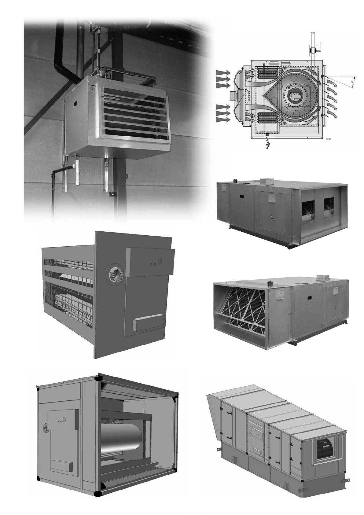
GASFIRED (MODULATING) CONDENSING PREMIX HIGH EFFICIENCY UNIT AIR HEATER
GASBEFEUERTE (MODULIERENDE) BRENNWERTWARMLUFTERZEUGER
AÉROTHERME GAZ MODULANT À CONDENSATION (SUSPENDU)
GASGESTOOKTE CONDENSERENDE MODULERENDE (HANGENDE) LUCHTVERWARMER
0.0
0.0
0.0
0.0
GS+ / G+ MODULE
CE 0063BP3341
NOx BP005
07/06
TB0008.2
Page 2
2
T: Type/Typ
Modèle
Dimensions mm
Abmessungen mm
Dimensions mm
Maatvoering mm
ML
0
T ABCDEFGHIJKLMNOPQRSU
35 969 875 810 739 35 105 600 165 110 90 560 470 275 120 80 240 120 97 175 3/4”
40 969 875 810 739 35 105 600 165 110 90 560 470 275 120 80 240 120 97 175 3/4”
60 969 1120 810 739 35 105 600 165 110 90 560 715 275 120 100 230 140 97 175 3/4”
80 969 1305 810 739 35 105 600 165 110 90 560 890 275 120 100 230 140 97 175 1”
100 979 1595 810 739 35 105 600 165 110 90 560 1180 275 120 100 230 140 97 175 1”
150 1180 1890 1000 1000 35 105 790 190 175 75 850 1455 295 165 130 250 225 140 170 1”
S
M10 (4x)
U
R
*
K J
ø
N
D
ø
QP
C
G
F
Raccordement condensation ø 40mm
Condensation drain ø 40mm
Kondensatanschluss ø 40mm
H
D
A
E
I
B
Condensaataansluiting ø 40mm
* Gas connection / Gasanschluss / Raccordement gaz / Gasaansluiting
03-139
10 10 9 7 89
6 2 3 3.23.1 11 451
Page 3
3
GB
DE
FR NL
GS+
Technical data Technische Daten Donnees techniques Technische Informatie
Type Typ Modele Type 35 40 60 80 100 150
A Nominal input Gross cal. value Nennwärmebelastung Ho Puissance supérieur Nominale belasting (bw) A kW 38,8 44,4 66,7 88,8 114,4 166,7
B Nominal input Nett cal. value Nennwärmebelastung Hu Puissance inférieur Nominale belasting (ow) B kW 34,9 40,0 60,0 80,0 103,0 150
C Efficiency at 100% input Wirkungsgrad 100% Belastung Rendement 100% puissance Rendement vollast 100% C % 95,7 94,8 94,2 94,3 94,2 94,8
D Efficiency at 30% input Wirkungsgrad 30% Belastung Rendement 30% puissance Rendement deellast 30% D % 105,7 105,7 105,8 105,8 105,6 104,9
E G25 Gasconsumption (15°C) max/min G25 Anschlusswer t (15°C) max/min G25 Debit de gaz (15°C) max/min G25 Gasverbruik (15°) max/min E G25 M
3
/h 4,10-1,02 4,73-1,02 7,03-1,47 9,30-2,57 11,98-3,23 17.05-3.75
CO2: max input CO2: max. Wärmebelastung CO2: max puissance CO2: max belasting % 9,0 9,0 9,0 9,0 9,0 8,9
Offset setpoint min input Offset Einstellung min. Wärmebelastung Offset, point de consinge min. Puissance Offset instelling min. belasting Pa -2 -2 -6 -11 -16 -38
Gas inlet pressure Gaseingangsdruck Pression d’alimentation Gasvoordruk mBar 25 25 25 25 25 25
G20 Gasconsumption (15°C) max/min G20 Anschlusswert (15°C) max/min G20 Debit de gaz (15°C) min/max G20 Gasverbruik (15°) max/min G20 M
3
/h 3,65-,088 4,18-0,88 6,22-1,34 8,16-2,25 10,67-2,94 15.3-3.37
CO2: max input CO2: max. Wärmebelastung CO2: max puissance CO2: max belasting % 8,8 8,8 8,8 8,8 8,8 8,5
Offset setpoint min input Offset Einstellung min. Wärmebelastung Offset, point de consinge min. Puissance Offset instelling min. belasting Pa -1,2 -1,2 -5 -10 -11 -54
Gas inlet pressure Gaseingangsdruck Pression d’alimentation Gasvoordruk mBar 20 20 20 20 20 20
G30 Gasconsumption (15°C) max/min G30 Anschlusswert (15°C) max/min G30 Debit de gaz (15°C) min/max G30 Gasverbr uik (15°) max/min G30 kg/h 2,92-0,72 3,46-0,72 5,05-1,11 6,70-1,89 8,48-2,48 12.35-2.72
CO2: max input CO2: max. Wärmebelastung CO2: max puissance CO2: max belasting % 11,1 11,1 10,8 10,8 10,7 10,7
Offset setpoint min input Offset Einstellung min. Wärmebelastung Offset, point de consinge min. Puissance Offset instelling min. belasting Pa +4 +4 -6 -5 -7 -70
Gas inlet pressure Gaseingangsdruck Pression d’alimentation Gasvoordruk mBar 29 29 29 29 29 29
G31 Gasconsumption (15°C) max/min G31 Anschlusswert (15°C) max/min G31 Debit de gaz (15°C) min/max G31 Gasverbr uik (15°) max/min G31 kg/h 2,68-0,64 3,17-0,64 4,72-1,04 6,22-1,72 8,03-2,29 11.69-2.57
CO2: max input CO2: max. Wärmebelastung CO2: max puissance CO2: max belasting % 10,3 10,3 10,2 10,1 10,2 10,3
Offset setpoint min input Offset Einstellung min. Wärmebelastung Offset, point de consinge min. Puissance Offset instelling min. belasting Pa +3,5 +3,5 -5 -5 -8 -63
Gas inlet pressure Gaseingangsdruck Pression d’alimentation Gasvoordruk mbar 37/50 1) 37/50 1) 37/50 1) 37/50 1) 37/50 37/50
F Turndown burner Regelbereich Brenner Plage bruleur Regelbereik brander F _:_ 4:1 5:1 5:1 4:1 4:1 4:1
G Flue gas temperature Abgastemperatur Temp. Gaz fumée Rookgastemperatuur (+/- 10°C) G °C 105 124 134 131 133 121
H NOx emmissions 3% O2 NOx Werte 3% O2 Emmissions Nox bas 3% O2 NOx emissie 3% O2 H ppm 32/7 42/7 42/9 41/16 45/11 37/16
I Burner blower start-max-min Brennerventilator Star t-max-min Ventilateur bruleur démarrage-max-min Branderventilator start-max-min I min-1 3500/4450/1330 3500/5150/1330 2500/4960/1300 3500/5900/1840 3500/5800/1800 2250/5700/1400
J Available flue discharge pressure Zulässiger Abgaswiderstand Resistance fumée Toegestane rookgasweerstand J Pa 78 90 90 166 165 200
K Flue gas discharge/combustion air inlet diam. Abgas/ Ansaugöffnung Durchmesser Diam. Evacuation des gaz de combustion Diameter rookgasafvoer/luchttoevoer K Ø-Ø 80-80 80-80 100-100 100-100 100-100 130-130
L Power supply Elektrischer Anschluss Connection d’électrique Elektriciteit aansluiting L V/Hz 230/50 230/50 230/50 230/50 230/50 230/50
M1 Power consumption GS+ Elektrische Leistung GS+ Puissance électrique GS+ Elektrisch vermogen GS+ M1 kW 0,3 0,3 0,4 0,65 0,75 1,4
N Fuse Gerätesicherung Fusible Toestelzekering N A 6,3 6,3 6,3 6,3 6,3 10
O Protection class Schutzart Classification protection moteur Beschermklasse O IP 20 20 20 20 20 20
Q Air displacement (20°C) Luftleistung (20°C) Debit d’air (20°C) Luchtopbrengst (20°C) Q m
3
/h 5000 5000 6500 10000 12500 18500
R Delta T air Delta T Luft Delta T d’air Luchttemperatuur verhoging R T 20,0 22,8 26,3 22,8 23,5 23,1
S Throw Wurfweite Portee WorpS M 28-36 26-36 26-36 32-46 36-50 48-68
U Ambiant/ temperature min/max Umgebungstemperatur min/max Temp. Ambiante min./max. Omgevingstemperatuur min. /max U °C -15/+40 -15/+40 -15/+40 -15/+40 -15/+40 -15/+40
V Fan assembly Ventilator Ventilateur Ventilator(en) GS+ V Ø 500 500 560 (2x) 500 (2x) 560 (2x) 650
W Fan speed Ventilatordrehzahl Revolution de ventilateur Ventilator toerental W min-1 865 865 900 865 900 880
X Noise level 5m (side) Schallpegel 5m (seite) Niveau Sonore 5m côte Geluidsniveau 5m (zijde) X dB(A) 48 48 51 52 52 58
Y1 Weight GS+ Gewicht GS+ Poids GS+ Gewicht GS+ Y1 kg 95 95 111 136 155 230
Z Condens Kondensat Condensation Condensaat Z Ph 3,4 3,4 3,4 3,4 3,4 3,4
Z1 Lmax reset cable Lmax Kabel für Resettaste Lmax câble de réarmement Lmax reset kabel Z1 m/mm2 50,0/1,5 50,0/1,5 50,0/1,5 50,0/1,5 50,0/1,5 50.0/1.5
Max. condens flow Max. Kondendsat menge quantité maximale condensation Max. condensaat hoeveelheid ltr/h 2 2 3 4 5 6
1) NL, BE, DE 50 mbar
Information BE Information BE Donnees BE Informatie BE
Nominal input Nett cal. Value H gas / L gasNennwarmebelastung Hu H gas / L gas Puissance inférieur H gas / L gas Nominale belasti ng (ow) H gas / L gas kW 34,9 / 28,9 40 / 33,3 60 / 48,4 80 / 66,7 103 / 85,1 150 / 127.7
Output H gas / L gas Leistung H gas / L gas Puissance nominale H gas / L gas Vermogen H gas / L gas kW 33,4 / 27,6 37,9 / 31,4 56,6 / 45,7 75,8 / 63,1 97,1 / 80,2 141.8 / 121.3
Page 4
4
S
T B C D E F G H I Ø P Q R S U V1 V2 W1 W2 X Y Z
35 875 810 769 20 105 600 195 110 80 240 120 97 175 3/4” 810 - 875 760 608 101 57
40 875 810 769 20 105 600 195 110 80 240 120 97 175 3/4” 810 - 875 760 608 101 57
60 1120 810 769 20 105 600 195 110 100 230 140 97 175 3/4” 810 - 1120 1005 608 101 57
80 1305 810 769 20 105 600 195 110 100 230 140 97 175 1” 810 1110 1305 1190 608 101 57
100 1595 810 769 20 105 600 195 110 100 230 140 97 175 1” 810 1110 1595 1480 608 101 57
150 1890 1000 1030 20 105 790 210 175 130 235 225 140 170 1” - 1110 1890 1620 800 100 135
200
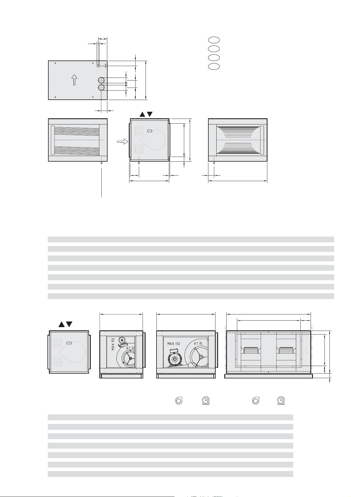
Type G+ m
3
/h m3/h m3/h m3/h
minimum nominal maximum typ max. max. typ max.
35 3760 5000 7200 12-12 112
40 3760 5000 7200 12-12 112
60 5640 6500 8640 12-12 112
80 7520 10000 - twin 12-19 112 13680 twin 15-11 132
100 9400 12500 - twin 12-12 112 16200 twin 15-11 132
150 14000 18500 - - - 20880 twin 15-15 132
200
T: Type/Typ
Modèle
Dimensions mm
Abmessungen mm
Dimensions mm
Maatvoering mm
Mark G+
*) Gas connection / Gasanschluss / Raccordement gaz / Gasaansluiting
Condensing unit
Kondensierende Ausführung
Modèle condensation
Condenserende uitvoering
*
Ventilator/
ventilateur:
0 - 500 Pa
Mark G+ Module
Indoor version
Innen Ausführung
Version interieur
Binnenopstelling
GB
DE
FR
NL
U
R
øø
N
D
PQ
C
GF
Condensation drain ø 40mm
Kondensat Anschluss ø 40mm
Connection pour condensation ø 40mm
Condensaataansluiting ø 40mm
H
D
V1 V2 W1
EI
B
W2 Z
XY
C80
Page 5

5
GB
DE
FR NL
G+
Technical data Technische Daten Donnees techniques Technische Informatie
Type Typ Modele Type 35 40 60 80 100 150
A Nominal input Gross cal. value Nennwärmebelastung Ho Puissance supérieur Nominale belasting (bw) A kW 38,8 44,4 66,7 88,8 114,4 166,7
B Nominal input Nett cal. value Nennwärmebelastung Hu Puissance inférieur Nominale belasting (ow) B kW 34,9 40,0 60,0 80,0 103,0 150
C Efficiency at 100% input Wir kungsgrad 100% Belastung Rendement 100% puissance Rendement vollast 100% C % 95,7 94,8 94,2 94,3 94,2 94,8
D Efficiency at 30% input Wirkungsgrad 30% Belastung Rendement 30% puissance Rendement deellast 30% D % 105,7 105,7 105,8 105,8 105,6 104,9
E G25 Gasconsumption (15°C) max/min G25 Anschlusswer t (15°C) max/min G25 Debit de gaz (15°C) max/min G25 Gasverbruik (15°) max/min E G25 m
3
/h 4,10-1,02 4,73-1,02 7,03-1,47 9,30-2,57 11,98-3,23 17.05-3.75
CO2: max input CO2: max. Wärmebelastung CO2: max puissance CO2: max belasting % 9,0 9,0 9,0 9,0 9,0 8,9
Offset setpoint min input Offset Einstellung min. Wärmebelastung Offset, point de consinge min. Puissance Offse t instelling min. belasting Pa -2 -2 -6 -11 -16 -38
Gas inlet pressure Gaseingangsdruck Pression d’alimentation Gasvoordruk mBar 25 25 25 25 25 25
G20 Gasconsumption (15°C) max/min G20 Anschlusswert (15°C) max/min G20 Debit de gaz (15°C) min/max G20 Gasverbr uik (15°) max/min G20 m
3
/h 3,65-,088 4,18-0,88 6,22-1,34 8,16-2,25 10,67-2,94 15.3-3.37
CO2: max input CO2: max. Wärmebelastung CO2: max puissance CO2: max belasting % 8,8 8,8 8,8 8,8 8,8 8,5
Offset setpoint min input Offset Einstellung min. Wärmebelastung Offset, point de consinge min. Puissance Offse t instelling min. belasting Pa -1,2 -1,2 -5 -10 -11 -54
Gas inlet pressure Gaseingangsdruck Pression d’alimentation Gasvoordruk mBar 20 20 20 20 20 20
G30 Gasconsumption (15°C) max/min G30 Anschlusswert (15°C) max/min G30 Debit de gaz (15°C) min/max G30 Gasverbr uik (15°) max/min G30 kg/h 2,92-0,72 3,46-0,72 5,05-1,11 6,70-1,89 8,48-2,48 12.35-2.72
CO2: max input CO2: max. Wärmebelastung CO2: max puissance CO2: max belasting % 11,1 11,1 10,8 10,8 10,7 10,7
Offset setpoint min input Offset Einstellung min. Wärmebelastung Offset, point de consinge min. Puissance Offse t instelling min. belasting Pa +4 +4 -6 -5 -7 -70
Gas inlet pressure Gaseingangsdruck Pression d’alimentation Gasvoordruk mBar 29 29 29 29 29 29
G31 Gasconsumption (15°C) max/min G31 Anschlusswert (15°C) max/min G31 Debit de gaz (15°C) min/max G31 Gasverbr uik (15°) max/min G31 kg/h 2,68-0,64 3,17-0,64 4,72-1,04 6,22-1,72 8,03-2,29 11.69-2.57
CO2: max input CO2: max. Wärmebelastung CO2: max puissance CO2: max belasting % 10,3 10,3 10,2 10,1 10,2 10,3
Offset setpoint min input Offset Einstellung min. Wärmebelastung Offset, point de consinge min. Puissance Offse t instelling min. belasting Pa +3,5 +3,5 -5 -5 -8 -63
Gas inlet pressure Gaseingangsdruck Pression d’alimentation Gasvoordruk mBar 37/50 1) 37/50 1) 37/50 1) 37/50 1) 37/50 1) 37/50
F Turndown burner Regelbereich Brenner Plage bruleur Regelbereik brander F _:_ 4:1 5:1 5:1 4:1 4:1 4:1
G Flue gas temperature Abgastemperatur Temp. Gaz fumée Rookgastemperatuur (+/- 10°C) G °C 105 124 134 131 133 121
H NOx emmissions 3% O2 NOx Werte 3% O2 Emmissions Nox bas 3% O2 NOx emissie 3% O2 H ppm 32/7 42/7 42/9 41/16 45/11 37/16
I Burner blower start-max-min Brennerventilator Star t-max-min Ventilateur bruleur démarrage-max-min Branderventilator start-max-min I min-1 3500/4450/1330 3500/5150/1330 2500/4960/1300 3500/5900/1840 3500/5800/1800 2250/5700/1400
J Available flue discharge pressure Zulässiger Abgaswiderstand Resistance fumée Toegestane rookgasweerstand J pa 78 90 90 166 165 200
K Flue gas discharge/ combustion air inlet diam. Abgas/ Ansaugöffnung Durchmesser Diam. Evacuation des gaz de combustion Diameter rookgasafvoer/luchttoevoer K Ø-Ø 80-80 80-80 100-100 100-100 100-100 130-130
L Power supply Elektrischer Anschluss Connection d’électrique Elektrische aansluiting L V/Hz 230/50 230/50 230/50 230/50 230/50 230/50
M2 Power consumption G+ module Elektrische Leistung G+ modul Puissance électrique G+ module Elektrisch vermogen G+ module M2 W 35 35 50 100 100 165
N Fuse Gerätesicherung Fusible Toestelzekering N A 6,3 6,3 6,3 6,3 6,3 6,3
O Protection class Schutzart Classification protection moteur Beschermklasse O IP 20 20 20 20 20 20
P Air pressure drop Geräteluftwiderstand Perte de charge Drukval unit luchtzijdig P pa 110 110 110 120 120 120
Q Air displacement (20°C) Luftleistung (20°C) Debit d’air (20°C) Luchtopbrengst (20°C) Q M
3
/h 3760-7200 3760-7200 5640-8640 7520-13680 9400-16200 14200-20880
R Delta T air Delta T Luft Delta T d’air Luchttemperatuur verhoging R ∆T 26,6-13,9 30-15,7 30-19,6 30-16,5 30-17,4 30-20,2
T Max duct pressure Max. Umgebungsdruck Pression externe Max. toelaatbare systeemdruk T Pa 600 600 600 600 600 600
U Ambiant/ temperature min/max Umgebungstemperatur min/max Temp. Ambiante min./max. Omgevingstemperatuur min. /max U °C -15/+40 -15/+40 -15/+40 -15/+40 -15/+40 -15/+40
Y2 Weight G+ module Gewicht G+ Modul Poids G+ module Gewicht G+ module Y2 kg 75 75 86 103 114 202
Z Condens Kondensat Condensation Condensaat Z Ph 3,4 3,4 3,4 3,4 3,4 3,4
Z1 Lmax reset cable Lmax Kabel für Resettaste Lmax câble de réarmement Lmax reset kabel Z1 m/mm2 50,0/1,5 50,0/1,5 50,0/1,5 50,0/1,5 50,0/1,5 50.0/1.5
Max. condens flow Max. Kondendsat menge quantité maximale condensation Max. condensaat hoeveelheid ltr/h 2 2 3 4 5 6
1) NL, BE, DE 50 mbar
Information BE Information BE Donnees BE Informatie BE
Nominal input Nett cal. Value H gas / L gas Nennwärmebelastung Hu H gas / L gas Puissance inférieur H gas / L gas Nominale belasting (ow) H gas / L gas kW 34,9 / 28,9 40 / 33,3 60 / 48,4 80 / 66,7 103 / 85,1 150 / 127.7
Output H gas / L gas Leistung H gas / L gas Puissance nominale H gas / L gas Vermogen H gas / L gas kW 33,4 / 27,6 37,9 / 31,4 56,6 / 45,7 75,8 / 63,1 97,1 / 80,2 141.8 / 121.3
Page 6
6
Page 7
7
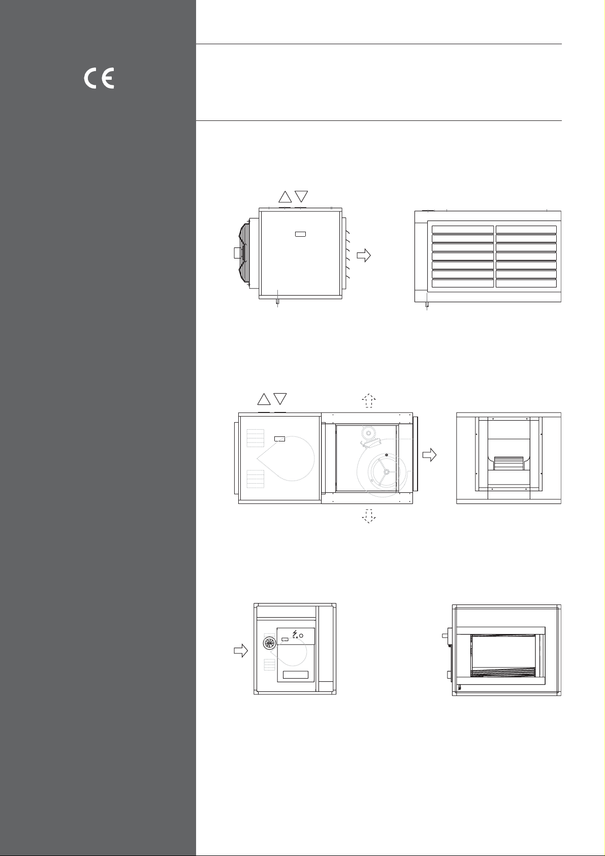
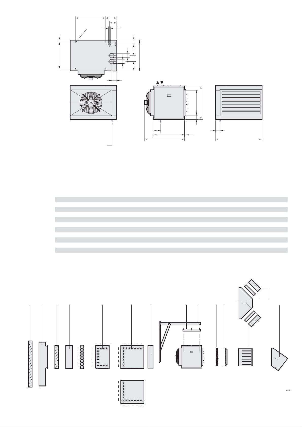
Dimensional drawings and diagrams for the G + Module standard condensing unit.
Refer to page 2 and 4 for information about the set-up, technical data, centrifugal
fans and related cabinet size.
The choice of fan will be based on the specified specifications. The following can
be the determining factors: amount of air,inter nal and external pressure in the
system, filters to be fitted, most economical motor capacity, noise calculations
and any methods to restrict noise levels.
The external static air pressure stated on the tecnical plate must reflect actual
site conditions. Where these differ it can lead to potential problems with motors
and the heater’s safety cut out sensors and /or combustion chamber and heat
exchanger.
Built-in examples in relation to the G + Module in an expanded air-handling unit.
Skizzen mit Maßangaben für GS+ und das Basisgerät des G+ Moduls in kondensierender Ausführung, siehe Seite 2 und 4.
Für Aufbau, technische Daten, zu verwendende Radialventilator und entsprechende
Kastengröße siehe Seite 4.
Die Auswahl des Ventilators wird anhand der angegebenen Spezifikationen
getroffen.
Entscheidend sind u. A.: Luftmenge, in- und externer Druck im System, ggf. zu
verwendende Filter,die effizienteste Motorleistung und die Berechnung der
Lärmbelastigung für ggf. zu verwendende lärmhemmende Maßnahmen.
Ein Radialventilator kann, im Gegensatz zum Axilalventilator,Widerstand von
Filtertaschen und/ oder Luftkänalen überwinden.
Der Widerstand eines Kanalsystem ist eine externe Pressung.
Die zulässige externe Pressung steht auf dem Typenschild des
Ventilatorgehäuses. Die externe Pressung auf dem Typenschild muß eingehalten
werden!
Bei Abweichungen dieser Werte kann der Motor überlastet werden und / oder der
Wärmetauscher zu warm werden so das der Sicherheitstemperaturbegrenzer
abschaltet
Einbaubeispiele für die Verwendung des G+ Moduls in einem Lüftungsgerät.
Croquis sur mesure de l’appareil GS+ et de base du module G+ dans une présentation condensée, voyez page 2 et 4. Pour plus de détails sur l’installation, les
spécifications techniques, la mise en marche des ventilateurs centrifuges et les
dimensions des armoires correspondantes, reportez-vous à la page 4
La sélection des ventilateurs dépend des spécifications données, notamment de
la quantité d’air, de la pression interne et externe du système, de la mise en
place de filtres (le cas échéant), de la puissance moteur la plus économique et
du calcul sonore pour la mise en application de mesures permettant de limiter les
bruits.
Contrairement à un ventilateur axial, un ventilateur centrifuge peut vaincre les
pertes de charges de filtres et/ou gaines de distribution d’air. La pression d’un
réseau de gainage est une pression externe. Cette pression externe est indiquée
sur la plaquette signalétique du caisson ventilateur.
Il y à lieu de garder la pression indiquée sur la plaquette signaltique!
Des anomalies de pression externe peuvent causer la surcharge de moteurs et/
ou la surchauffe de l’échangeur de chaleur / thermostat maximal.
Exemples d’installation pour la mise en marche du module G+ dans un système de
traitement de l’air étendu.
Maatschetsen GS+ en voor het basistoestel van de G+ Module in condenserende
uitvoering, zie pagina 2 en 4.
Voor opstelling, technische gegevens, toe te passen centrifugaal ventilatoren en
bijbehorende kastgrootte zie pagina 4.
De ventilatorselectie wordt bepaald aan de hand van de opgegeven specificaties.
Bepalend zijn o.a.: Luchthoeveelheid, in- en externe druk in het systeem,
eventueel toe te passen filters, het meest economische motorvermogen en de
geluidsberekening voor eventueel toe te passen geluidremmende maatregelen.
Een centrifugaal ventilator kan in tegenstelling tot een axiaal ventilator een luchtweerstand van filters en / of luchtkanalen overwinnen. De weerstand van een
kanalensysteem is een externe weerstand. De externe weerstand is op de
typeplaat van de ventilatoromkasting vermeld.
De op de typeplaat vermelde externe weerstand moet worden aangehouden!
Afwijkingen van de externe druk kan aanleiding zijn van overbelaste motoren en/of
het oververhit raken van de warmtewisselaar/maximaal thermostaat.
Inbouwvoorbeelden voor toepassing van de G + Module in een uitgebreide
luchtbehandelingskast.
Appareil de base du module G+
FR
G+ module basistoestel
NL
G+ module standard unit
GB
G+ Modul Basisgerät
DE
Page 8
8
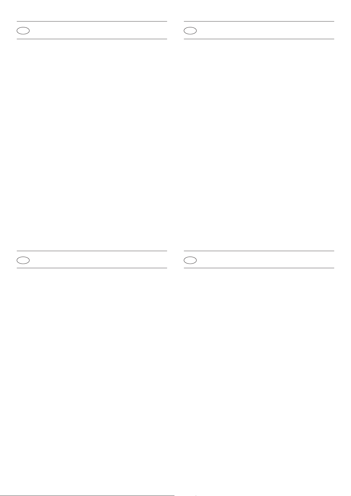
35 40 60 80 100 150 200*
C 430 430 450 450 450 600 600
D 780 780 780 780 780 1100 E 130 130 200 200 200 300 300
E’ 350 350 450 450 450 600 600
F
x
[min] 400 400 400 400 400 400 400
F
2
[adv] 4000 4000 4500 5000 5000 7000 x
G 600 600 600 600 700 750 750
J [min] 1400 1400 1600 1800 2200 2600 x
Page 9

9
Technical manual - information
Installation
After unpacking the unit check it for damage. Check that the type/model, the
power supply (230 V/50 Hz) and the gas category are correct.
General Information
Keep the technical manual in or near the unit.
The fitter and the user must follow the instructions in relation to the installation
and use of the unit. Incorrect installation or use may lead to the unit being damaged.
Any manufacturers liability under contract provisions or otherwise, for damage to
persons or machinery is rendered null and void resulting from wrong installation or
misuse of the unit.
Manufacturers liability is also rendered null and void through non- adherence with
the manufacturer’s instructions.
Qualified personnel only must perform service and maintenance wor k. Should this
condition not be followed, the manufacturers warranty will be null and void.
National and any regional and locally applicable regulations must be followed
when installing the unit. Refer, in par ticular, to the latest publication. The unit
must only be installed in areas suitable for these units.
Minimum Required Clearance
Ensure, especially,that the required clearance is available for maintenance work
on the burner and the gas control equipment. Ensure there is sufficient clearance
for the suction of the process air and that there is an unimpeded outlet for the
heated air to avoid the danger of scorching (refer to diagrams 03-1432 and the
table on page 8).
*) Not yet available
F2 Recommended suspension height.
Montage
Überprüfen Sie das Gerät nach dem Auspacken auf Beschädigungen. Überprüfen Sie
die Richtigkeit des Typs/Models, die elektrische Spannung (230 Volt / 50 Hz ) und
die richtige Gasart.
Allgemein
Bewahren Sie das technische Handbuch im oder in der Nähe des Gerätes auf.
Der Installateur und der Benutzer haben die Vorschriften hinsichtlich der
Installation und des Gebrauchs des Geräts einzuhalten. Unsachgemäße
Installation oder unsachgemäßer Gebrauch können Schäden am Gerät zur Folge
haben. Hierdurch verfällt die Werksgarantie.
Die Wartungs- und Instandhaltungsarbeiten dürfen ausschließlich von hierzu befugten Fachkräften durchgeführt werden; anderenfalls verfällt die Werksgarantie.
Bei der Montage des Gerätes sind die geltenden nationalen und ggf. regionalen
und lokalen Vorschriften zu beachten. Im Besonderen wird auf die neueste
Ausgabe der Gasinstallationsvorschriften verwiesen. Das Aufstellen des Gerätes
darf ausschließlich in hierfür geeigneten Räumen und auf hierfür geeigneten
Plätzen geschehen.
(BE)
Anweisung:
Für das Aufstellen und den Betrieb des Geräts müssen die technischen Vorschriften
sowie alle anwendbaren Bau- und gesetzlichen Bestimmungen beachtet werden. Der
Warmlufterzeuger ist gemäß der Belgischen Norm NBN D51-003 aufzustellen.
Erforderlicher freier Mindestraum
Achten Sie vor allem hinsichtlich der Wartung des Brenners und des Gassteuerblocks auf den erforderlichen freien Raum.
Achten Sie in Hinblick auf eine mögliche Brandgefahr auf ausreichend Raum für
das Ansaugen der Heizluft und das ungehinderte Ausblasen der Heizluft (siehe
Zeichnungen 03-1432 und Tabelle Seite 8).
*) Nog nicht Lieferbar
F2 Empfohlene Aufhängehöhe
GB
Technisches Handbuch - Informationen
DE
Manuel Technique - informations
Installation
Vérifiez après déballage que l’appareil ne présente pas de traces de détériorations. Vérifiez le type/modèle, la tension électrique
(230 V/50 Hz) et la catégorie du gaz.
Généralités
Conservez le manuel technique dans ou à proximité de l’appareil. Les personnes
chargées de l’installation et de l’utilisation doivent respecter les consignes relatives à l’installation et à l’utilisation de l’appareil.
Une installation ou une utilisation incorrecte peut entrainer des dommages au
niveau de l’appareil. La garantie du fabricant est alors annulée.
Les travaux d’entretien et de maintenance doivent uniquement être réalisés par
du personnel qualifié, faute de quoi la garantie du fabricant est annulée.
Lors de l’installation de l’appareil, vous devez respecter les consignes nationales
et locales en vigueur. Nous vous renvoyons notamment à la dernière publication
des consignes d’installation relatives au gaz.
L’installation de l’appareil doit uniquement être réalisée dans des espaces adaptés, à un emplacement adapté.
(BE)
Avertissement:
Lors de l’installation et de l’utilisation de l’appareil, veillez à respecter
les consignes techniques ainsi que les règlements de construction et la législation en vigueur. Le chauffage installé doit être conformé à la norme Belge NBN
D51-003.
Espace libre nécessaire
Veillez à laisser suffisamment d’espace autour du brûleur et de l’appareil de
réglage du gaz pour permettre les travaux d’entretien. Afin d’éviter tous risques de
brûleures, laissez suffisamment d’espace devant l’alimentation d’air du chauffage
et n’entravez pas la sortie de l’air chaud (reportez-vous aux illustrations 03-1432
et au tableau page 8).
*) N’est pas livrable
F2 Hauteur de suspension recommandée
Installatie
Controleer, na het uitpakken, het toestel op beschadiging. Controleer de juistheid
van het type /model , de elektrische spanning (230 Volt / 50 Hz) en de juiste
gascategorie.
Algemeen
Bewaar het technisch boek in - of in de nabijheid van het toestel.
De installateur en de gebruiker dienen de voorschriften ten aanzien van installatie
en gebruik van het toestel aan te houden.
Onjuiste installatie of onjuist gebruik kan schade aan het toestel tot gevolg
hebben. Hierdoor vervalt de fabrieksgarantie.
De servicewerkzaamheden en onderhoudswerkzaamheden mogen alleen
uitgevoerd worden door bevoegd personeel anders vervalt de fabrieksgarantie.
Bij installatie van het toestel dienen de geldende landelijke- en eventuele
regionale- en plaatselijke voorschriften te worden aangehouden. In het bijzonder
wordt verwezen naar de nieuwste uitgave van de gasinstallatievoorschriften.
Het installeren van het toestel mag slechts in een daartoe geschikte ruimte en op
een daartoe geschikte plaats geschieden.
(BE)
Aanwijzing:
Voor de installatie en de werking van het toestel moeten de regels van de
techniek gerespecteerd worden, evenals alle bouw- en wettelijke bepalingen die
van toepassing zijn. De luchtverwarmer dient conform de Belgische norm
NBN D51-003 te worden geïnstalleerd.
Minimaal benodigde vrije ruimte
Let vooral op de benodigde vrije ruimte voor onderhoud aan de brander en de
gasregelapparatuur.
Let, in verband met schroeigevaar, op voldoende ruimte voor de aanzuig van de
verwarmingslucht en een ongehinderde uitblaas van de verwarmde lucht
(zie tek. 03-1432 en tabel blz. 8).
*) Nog niet beschikbaar
F2 Geadviseerde ophanghoogte.
FR
Technisch boek - Info
NL
Page 10
10
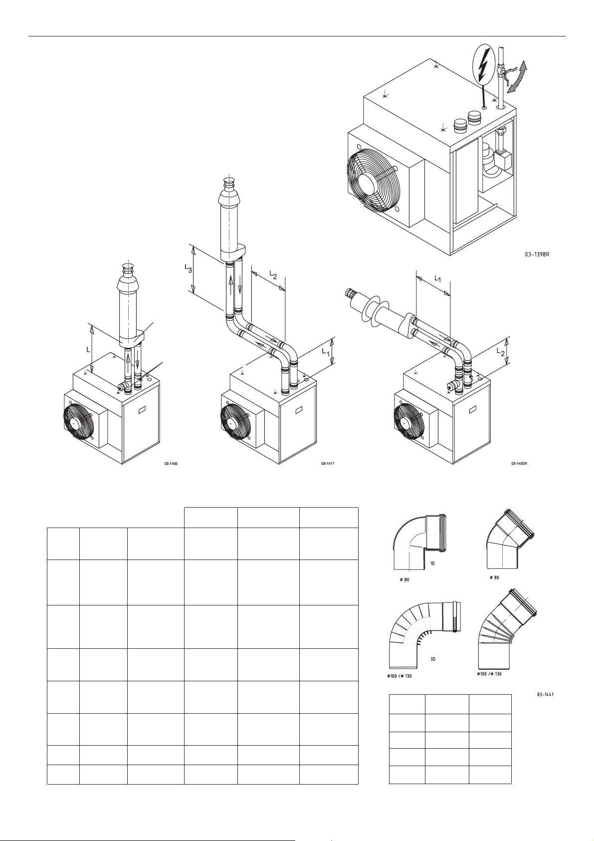
Pos. A Pos. B Pos. C
Type D.norm. du/di L MAX L1+L2+L3 L1+L2
ø mm ø mm m m m
35 80 80/80 2x13,0 2x9,6 2x11,3
80 100/100 2x38,0 2x34,2 2x36,1
100 100/100 2x52,0 2x48,2 2x50,1
40 80 80/80 2x10,5 2x71 2x8,8
80 100/100 2x31,5 2x27,7 2x29,6
100 100/100 2x45,5 2x41,7 2x43,6
60 100 100/100 2x15,0 2x11,2 2x13,1
100 130/130 2x52,5 2x48,5 2x50,5
80 100 100/100 2x17,0 2x13,2 2x15,1
100 130/130 2x60,5 2x56,9 2x58,5
100 100 100/100 2x5,0 2x1,2 2x3,1
100 130/130 2x19,0 2x15,0 2x17,0
150 130 130/130 2x26,5 2x22,5 2x24
200 130 130/130
1D 3D 3D
ø80 ø100 ø130
-m -m -m
1,0 1,2 1,3 45˚
1,7 1,9 2,0 90˚
pos. A
C33
pos. C
C33
du/di
Dnorm
pos. B
C33
Page 11
11
Gas supply and gas connection
An approved gas stopcock with the correct diameter must be installed
near the unit (refer to diagram 03-1398R).
Check whether the gas type agrees with the specification on the tecnical type
plate before putting the unit into service.
Also check whether the gas supply pressure agrees with the specifications on the
technical type plate.
Carefully clean the gas pipe before putting the unit into operation. This will
prevent damage to the gas control module of the unit. Next, bleed the gas pipe.
In der Nähe des Gerätes ist ein genehmigter Gasabsperrhahn mit dem richtigen
Durchmesser anzubringen (siehe Zeichnung 03-1398R). Überprüfen Sie vor
Inbetriebnahme des Gerätes, ob die Gasart mit der Angabe auf dem Typenschild
übereinstimmt.
Überprüfen Sie gleichzeitig, ob der Gasfliessdruck mit dem Typenschild übereinstimmt.
Vor Inbetriebnahme des Gerätes ist die Gasleitung sorgfaltig zu reinigen.
Hierdurch wird einer Beschädigung der gasführenden Teile des Gerätes vorgebeugt. Die Gasleitung anschließend entlüften
GB
Gaszufuhr und Gasanschluss
DE
Alimentation en gaz et raccordement du gaz
Il est nécessaire d’installer un robinet de gaz normalsé, de diamètre correct, à
proximité de l’appareil (reportez-vous à l’illustration 03-1398R). Lors du démarrage de l’appareil, assurez-vous que le type de gaz délivré est conforme avec les
indications de la plaque de désignation. Vérifiez également que la pression d’arrivée du gaz est conforme avec les indications de la plaque de désignation.
Nettoyez soigneusement la conduite de gaz avant de mettre l’appareil en fonctionnement. Cette opération permet d’éviter d’endommager l’alimentation en gaz de
l’appareil et de purger la conduite de gaz.
In de nabijheid van het toestel dient een goedgekeurde gasstopkraan, van de
juiste diameter te worden aangebracht (zie tek. 03-1398R). Controleer voor het
opstarten van het toestel of de gassoor t overeenkomt met de opgave op de
typeplaat.
Controleer tevens of de gasaanvoerdruk overeenkomt met de typeplaat.
Voor het in gebruik nemen van het toestel de gasleiding zorgvuldig reinigen.
Hierdoor wordt beschadiging van de gasvoerende delen van het toestel
voorkomen, daarna de gasleiding ontluchten.
FR
Gastoevoer en gasaansluiting
NL
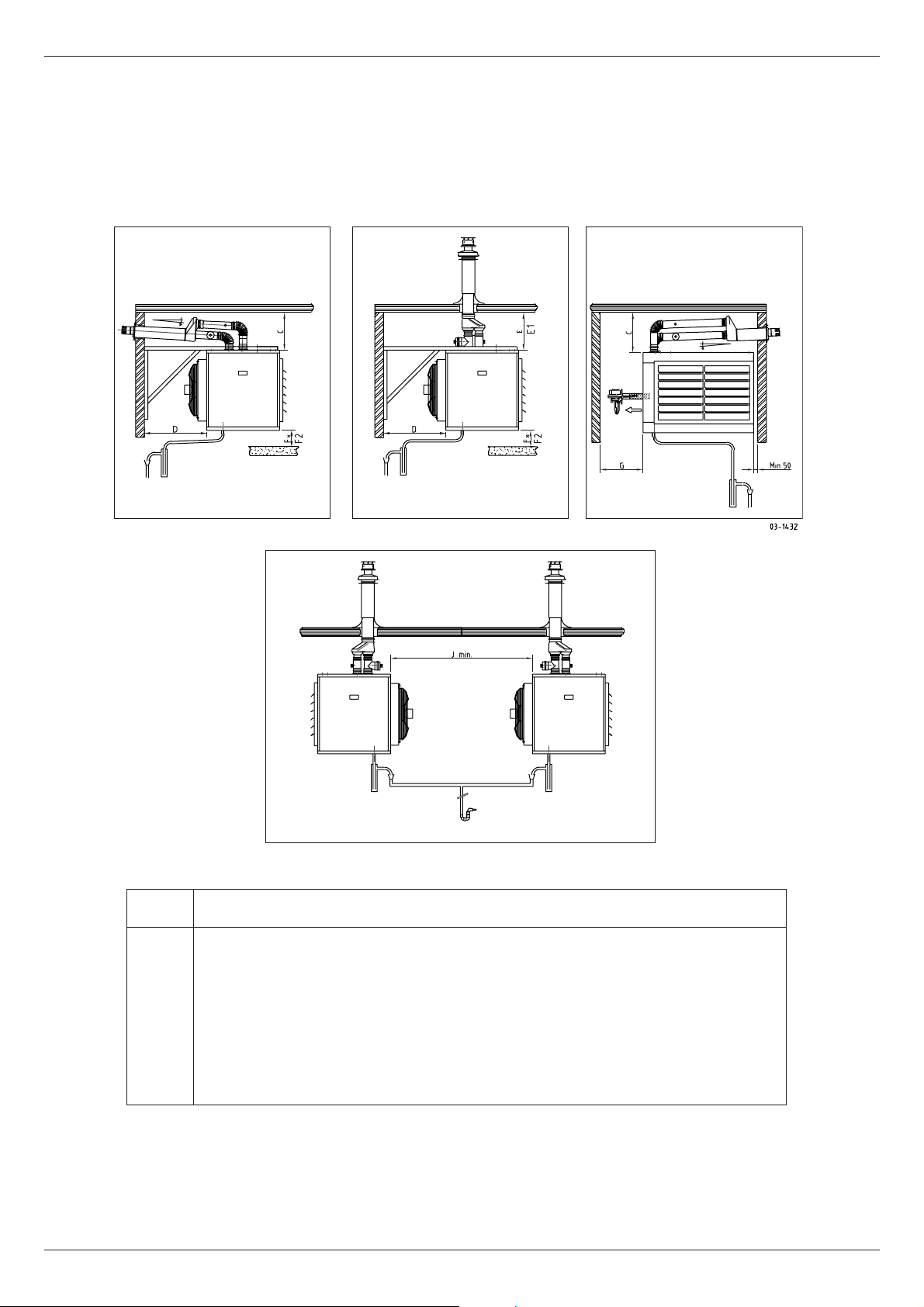
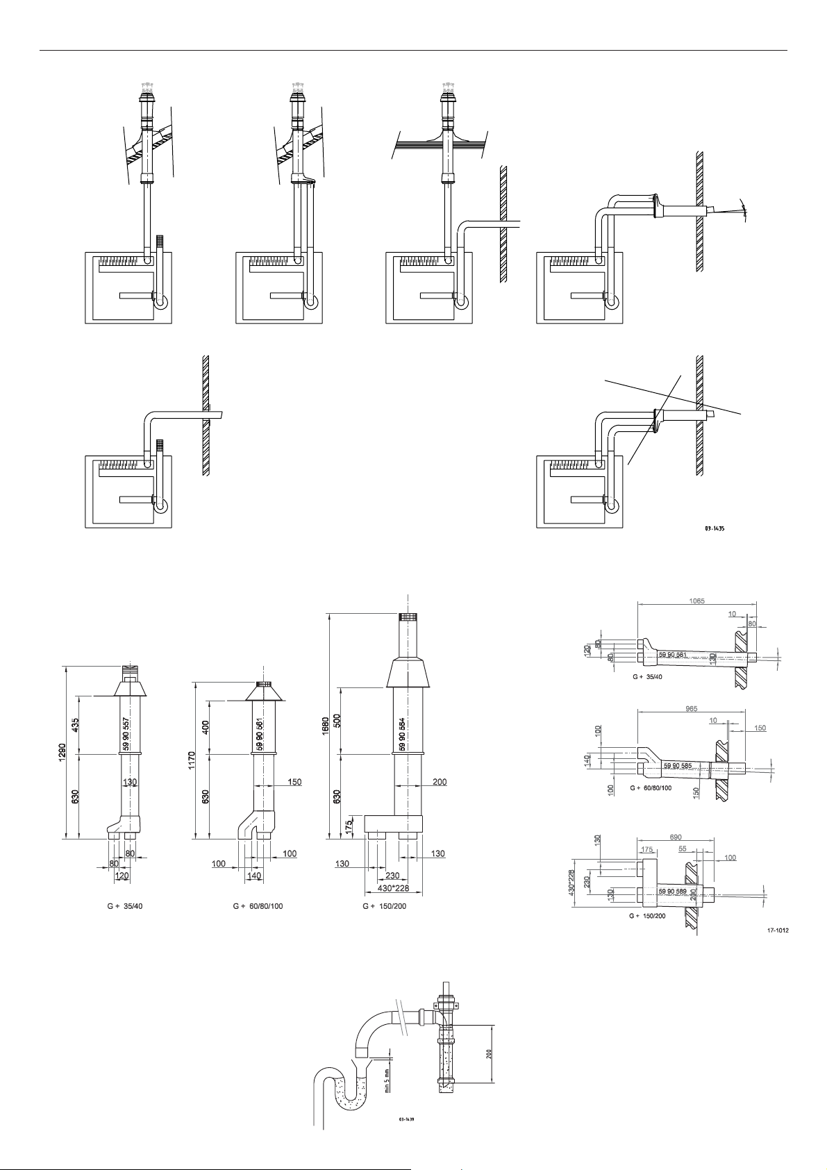
Combustion air supply and flue pipe
Combustion air supply and flue pipes must have as few bends as possible; resistance must, in general, be limited to a minimum.
A resistance that is too high in relation to the pipe system may reduce the gas
technical load (refer to diagrams 03-1417, 03-1420 R and 03-1405 and the table
on page 10).
The combustion air supply and the flue pipes must not be supported on the unit
but must be appropriately suspended.
Flue pipes must be fitted falling towards the unit for condensing units. The resistance table given on page 10 only applies to the flue material supplied and/or
recommended by the manufacturer.
Verbrennungsluftzufuhrleitungen und Rauchgasableitungen sollten möglichst wenig
Krümmungen haben; im Allgemeinen muss der Widerstand auf ein Minimum
beschränkt werden. Ein zu hoher Widerstand in der Trasse kann die gastechnische
Belastung mindern (siehe Zeichnungen 03-1417, 03-1420 R, 03-1405 und Tabelle
Seite 10).
Die Verbrennungsluftzufuhrleitungen und die Rauchgasableitungen dürfen nicht am
Gerät abgestützt, sondern zweckmäßig aufgehangen werden.
Die Rauchgasableitungen sind für kondensierende Einheiten zum Gerät hin
abschüssig zu legen.
Die Widerstandstabelle auf Seite 10 gilt ausschließlich für die von Hersteller.gelieferten bzw. empfohlenen Abgasmaterialien.
GB
Verbrennungsluftzufuhr und Rauchgasableitung
DE
Alimentation d’air du chauffage et
évacuation des gaz de fumée
Evitez, dans la mesure du possible, de recourber les conduites d’alimentation en
air du chauffage et les conduites d’évacuation des gaz de fumée. La perte de
charge doit généralement être limitée au minimum. Si la perte de charge des
conduites est trop élevée, la charge technique du gaz risque de diminuer (reportez-vous aux illustrations 03-1417, 03-1420 R et 03-1405 et au tableau page 10).
Les conduites d’alimentation en air du chauffage et les conduites d’évacuation
des gaz de fumée ne doivent pas être détachées de l’appareil. Elles doivent néanmoins être suspendues de manière efficace.
Les conduites d’évacuation des gaz de brûlés doivent respecter les permettant
l’évacuation des condensats vers l’appareil.
Le tableau des pertes de charge de la page 10 s’applique exclusivement aux
matériaux d’évacuation fournis ou recommandés par le fabrikant.
Verbrandingsluchttoevoerleidingen en rookgasafvoerleidingen dienen zo weinig
mogelijk bochten te hebben; in het algemeen moet de weerstand tot een minimum beperkt worden. Een te hoge weerstand in het tracé kan de gastechnische
belasting verlagen (zie tek. 03-1417, 03-1420 R, 03-1405 en tabel blz. 10).
De verbrandingsluchttoevoerleidingen en de rookgasafvoerleidingen mogen niet op
het toestel afgesteund worden, maar dienen doelmatig te worden opgehangen.
Rookgasafvoerleidingen dienen voor condenserende units op afschot naar het toestel toe te worden gelegd.
De weerstandtabel op pag. 10 geldt uitsluitend voor het door de fabrikant geleverd resp. geadviseerd afvoermateriaal.
FR
Verbrandingsluchttoevoer en rookgasafvoer
NL
Page 12
12
C33:
C13:
B23
B23 C13
C33/C63 C53 C13
Page 13
13
Possible flue pipe/combustion air supply
The GS+ and the G + Modules are suitable for the following flue systems:
B23; C13; C33; C53 and C63.
You can find the meaning of the above symbols in the drawings (page 12). The
extension pipes must only be installed in parallel.
Flue pipes must, by preference, be made of stainless steel. The air suction pipes
can be provided in thin-walled aluminium or in Poly- Propylene.
Attention! The flue tube construction C63 must meet the GASTEC QA mark for
condensing units with a continuously allowable flue gas temperature of 160
degrees Celsius.
Attention! The values specified in the resistance table only apply to the flue material supplied and recommended, by the manufacturer. Flue material with a different
resistance may influence the length of the total supply and exhaust layout.
Attention! The pH value of the condensed water is 3.4!
Condensate connection
The condensate produced in the air heater must be drained using a connection to
a drain. The piping must be made of plastic with an inside diameter that agrees
with the national standard and must have been provided with a collecting funnel
and a gully trap.
You are not permitted to drain condensate through a roof (gutter)
(freezing may occur).
Note: Ensure that the distance between the outlet of the condensation drain and
the drainage pipe is at least 5 mm and at most 10 mm.This will ensure that the
required open connection is obtained. Maintenance work on the unit will also be
easier.
Die GS+ und die G + Module sind geeignet für die Ableitungssysteme:
B23, C13, C33, C53 und C63.
Die Bedeutung der Symbole finden Sie in den Skizzen auf Seite 12. Die
Verlängerungsrohre sind ausschließlich parallel zu verlegen. Vorzugsweise werden
Rauchgasableitungsrohre aus Edelstahl verwendet.
Die Luftansaugrohre können aus dünnwändigem Aluminium oder aus
Polypropylen gefertigt sein.
Achtung: die Ableitungskonstruktion C63 muss dem Gastec QA-Prüfzeichen für
kondensierende Geräte mit einer kontinuierlichen zulässigen Rauchgastemperatur
von 160 Grad Celsius.
Achtung: Die in der Widerstandstabelle angegebenen Werte gelten ausschließlich für
die von Hersteller gelieferten bzw. empfohlenen Abgasmaterialien. Abgasmaterial mit
einem abweichenden Widerstand kann die Länge der gesamten Zufuhr- und
Abgastrasse beeinflussen.
Achtung: Der pH-Wert des Kondenswassers beträgt 3,4!
Kondensationsanschluss
Das im Warmlufterzeuger gebildete Kondensat muss mittels einer offenen
Verbindung zum Kanal abgeführt werden. Die Leitung muss aus Kunststoff gefertigt
und mit einem Auffangtrichter und einem Siphon versehen sein.
Das Abführen von Kondensat zu einem Dach bzw. einer Dachrinne ist aufgrund der
Gefriergefahr nicht erlaubt.
NB: Sorgen Sie dafür,dass der Abstand zwischen der Austrittsöffnung der Kondensatableitung und der Ableitung mindestens 5 mm und höchstens 10 mm beträgt.
Hierdurch entsteht die erforderliche offene Verbindung,die darüber hinaus die
Wartung des Gerätes einfacher macht.
BE: Abgas system C63 ist in Belgien nicht erlaubt.
GB
Mögliche Rauchgasableitung und
Verbrennungsluftzufuhr
DE
Alimentation d’air du chauffage et
évacuation des gaz de fumée possibles
Les modules GS+ et G+ sont adaptés aux systèmes d’évacuation suivants:
B23; C13; C33; C53 et C63.
La signification de ces symboles est détaillée dans les croquis (page 12).
Les conduites d’extension doivent uniquement être installées en parallèle.
Les conduites d’évacuation des gaz de fumée doivent de préférence être constituées d’ INOX. Les conduites d’alimentation en air doivent être constituées
d’aluminium fin ou de PP.
Attention: la structure d’évacuation C63 doit être conforme aux exigences Gastec
QA relatives aux appareils de condensation avec une température des gaz de
fumée maximale autorisée de 160º C . Attention: les valeurs données dans le
tableau des pertes de charge s’appliquent exclusivement aux matériaux d’évacuation des gaz de fumée fournis ou recommandés par le fabricant Les matériaux
d’évacuation dont la résistance ne correspond pas aux valeurs du tableau
peuvent influencer la longueur de l’ensemble du parcours d’alimentation et
d’évacuation.
Attention: la valeur du pH de l’eau condensée est égale à 3,4 !
Raccordement de condensation
La condensation générée dans le chauffage doit être évacuée à l’aide d’un
raccordement ouvert à l’égout. La conduite doit être constituée en matière
synthétique et être équipée d’un entonnoir de réception et d’un siphon.
L’évacuation de la condensation par le toit (gouttière) est interdite en raison des
risques de gel.
N.B.: veillez à ce que la distance entre la bouche d’évacuation de la condensation
et la conduite d’évacuation soit comprise entre 5 et 10 mm. Il est ainsi possible
d’obtenir le raccordement ouvert nécessaire. L’entretien de l’appareil est également
facilité.
Pour la Belgique: C63 structure d’évacuation est défendu.
De GS+ en de G + module zijn geschikt voor de afvoersystemen:
B23; C13; C33; C53 en C63.
De betekenis van deze symbolen zijn in de schetsen (pag. 12) weergegeven.
De verlengpijpen moeten uitsluitend parallel uitgevoerd worden.
Rookgasafvoerpijpen bij voorkeur in RVS uitvoeren.
De luchtaanzuigpijpen mogen in dunwandig aluminium of in PP uitge- voerd worden.
Let op: de afvoerconstructie C63 moet voldoen aan het Gastec QA keurmerk voor
condenserende toestellen met een continu toelaatbare rookgastemperatuur van
160 graden Celcius.
Let op: De in de weerstandtabel aangegeven waarden gelden uitsluitend voor de
door de fabrikant geleverde resp. geadviseerde rookgasafvoermaterialen.
Afvoermateriaal met een afwijkende weerstand kan de lengte van het totale toeen afvoertracé beïnvloeden.
Let op: ph-waarde condenswater bedraagt 3,4 !
*C63 afvoerconstructie is in België niet toegestaan.
Condensaansluiting
Het in de luchtverwarmer gevormde condensaat moet d.m.v. een open verbinding
op het riool worden afgevoerd. De leiding moet zijn vervaardigd van kunststof, met
een binnendiam. overeenkomstig de geldende voorschriften en zijn voorzien van
een opvangtrechter en een stankafsluiter. Tevens is van toepassing de
NEN 3287 (NL).
Het afvoeren van condensaat op een dak(goot) is i.v.m. bevriezingsgevaar, niet
toegestaan.
N.B.: Zorg er voor dat de afstand tussen de uitmonding van de condensafvoer en de
afvoerleiding minimaal 5 mm en maximaal 10 mm bedraagt. Hierdoor ontstaat de
vereiste open verbinding en is onderhoud aan het toestel eenvoudiger.
FR
Mogelijke rookgasafvoer/verbrandingsluchttoevoer
NL
Page 14
14
GS+ 35-100
G+ module 35-200
GS+ 150
Page 15

15
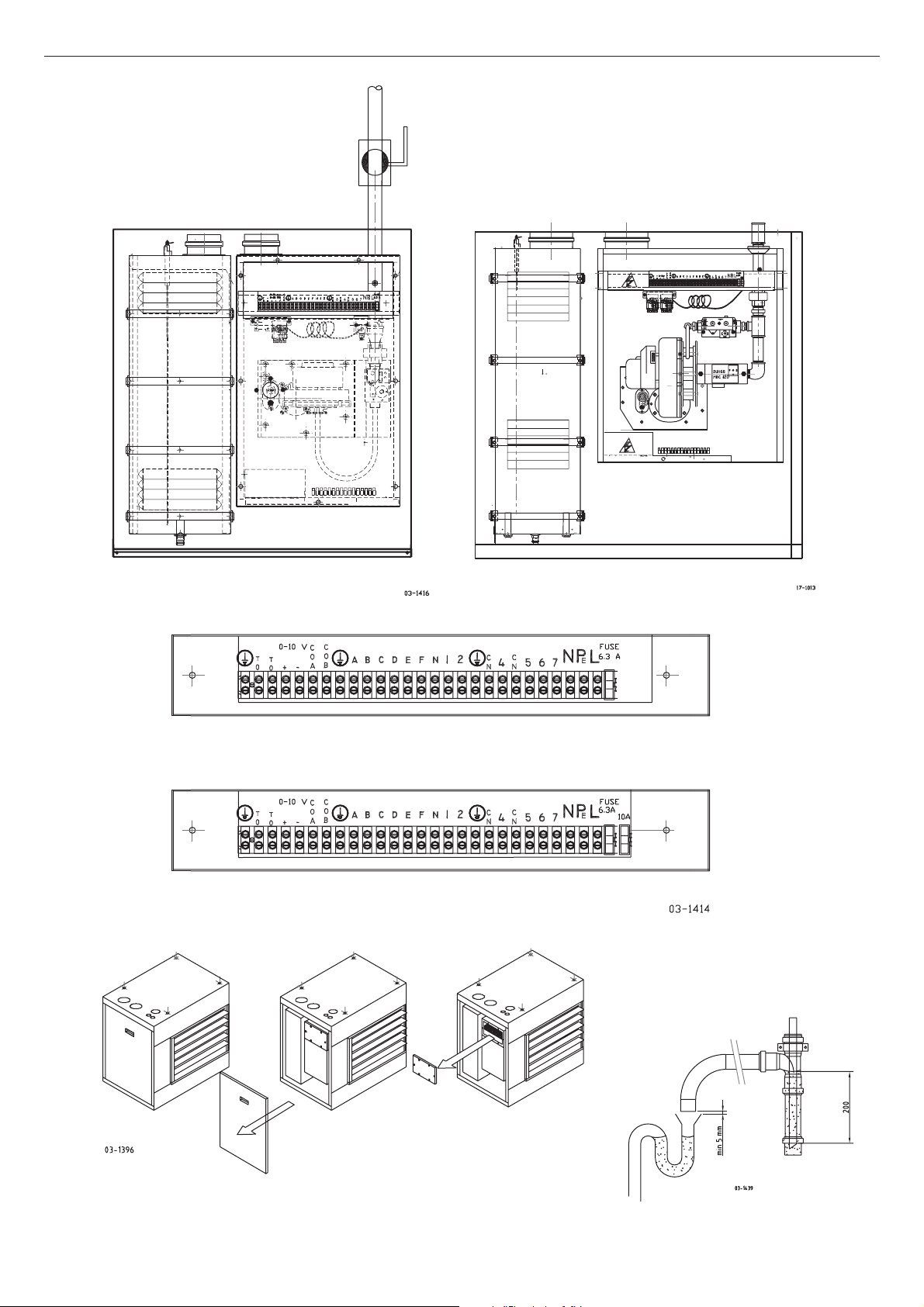
Electric connection
Check the electric current supply to ensure the voltage is correct and sufficient.
Check whether the unit has been provided with a reliable earth. Although the
microprocessor is not phase sensitive, we recommend that the phase and neutral
be connected to the terminals that have been earmarked for this purpose (refer to
diagrams 03-1416, 03-1414 and 17-1013).
The electrical diagram can be found on the inside of the cover of the electrical
console (refer to diagram 03-1396).
Operation
Operational Checks
- Switch off the electrical isolator switch.
- Set the room thermostat or signal from the building management system to the
minimum position.
- Disconnect the gas supply by closing the gas stopcock. Carefully open the gas
stopcock and bleed the gas pipes meticulously.
- Check the gas pipes for leaks after the gas pipes have again been connected
to the unit.
- Do not use naked flames under any circumstances!
- Next, again close the gas stopcock.
- Always install the siphon deliverd loose by Mark. Install the condensation from
the unit into the drain system. Remove the red cap.
- Check if the siphon has been installed correctly at a frost-free location and fill
it with water before putting the unit into operation (refer to diagram 03-1439).
- Check by GS+ if the air-outlet louvers have been opened min. 45º; refer to
diagram(see page 18).
- Units provided with a centrifugal fan, measure the external static pressure in
the system and check if it matches typ plate.
- Check rotation of the ventilator, see rotation sticker.
- Check motor amps and set ther mal overload.
Überprüfen Sie die elektrische Stromversorgung auf richtige und ausreichende
Spannung.
Überprüfen Sie, ob das Gerät mit einer geeigneten Erdung versehen ist. Obgleich der
Mikroprozessor nicht phasenempfindlich ist, ist es besser, wenn die Phase und die
Null an den hierfür bestimmten Klemmen befestigt werden (siehe Zeichnungen
03-1416, 03-1414 und 17-1013).
Das elektrische Schema befindet sich an der Innenseite der Abdeckung des
Gassteuerblocks (siehe Zeichnung 03-1396).
BE: Umstellen der Gasart ist in Begien nicht erlaubt.
Inbetriebnahme
Kontrollarbeiten für die Inbetriebnahme
- Schalten Sie den Reparaturschalter aus.
- Stellen Sie den Raumthermostat bzw. das Raumsignal aus dem
Gebäudeleitsystem auf die niedrigste Stufe ein.
- Koppeln Sie die Gasleitung nach Schließen des Gasabsperrhahns ab.
Öffnen Sie den Gasabsperrhahn vorsichtig und entlüften Sie die Gasleitung
sorgfältig.
- Überprüfen Sie die Gasleitung auf Leckagen, nachdem Sie die Gasleitung wieder
mit dem Gerät verbunden haben.
- Machen Sie auf keinen Fall ein offenes Feuer!
- Drehen Sie den Gasabsperrhahn anschließend wieder zu.
- Es ist notwendig den vom Hersteller gelieferten Syphon zu installieren.
Der kleine rote Deckel muß dazu entfernt werden.
- Überprüfen Sie, ob der Siphon korrekt und frostfrei montiert ist und befüllen sie
ihn vor Inbetriebnahme des Geräts mit Wasser (siehe Zeichnung 03-1439).
- Überprüfen Sie, beim GS+ ob die Lamellen der Ausblashaube auf Spaltbreite
gestellt sind (min. 45º offen, siehe Seite 18).
Warmlufterzeuger mit Radialgebläse: Externen statischern Systemdruck messen und
mit den Angaben auf dem Typenschild vergleichen. Die Drehrichtung des Ventilators
mit dem Drehrichtungskleber am Ventilator prüfen und anschließend die
Stromaufnahme (Ampere) prüfen.
GB
Elektrischer Anschluss
DE
Raccordement électrique
Assurezvous que la tension d’alimentation électrique est correcte.
Assurezvous que l’appareil dispose d’une mise à la terre fiable. Le microprocesseur est utilisé indépendamment des phases. Veuilliz vérifier que le neutre soit
bien raccordé (reportezvous aux illustrations 03-1416, 03-1414 et 17-1013).
Le schéma électrique est situé sur la partie intérieure du couvercle de l’appareil
(reportezvous à l’illustration 03-1396).
BE: Pour la Belgique: conversion des types de gaz n’est pas permis.
Mise en marche
Vérifications à effectuer avant la mise en marche
- Désactivez l’inter r upteur électrique.
- Réglez le ther mostat/signal de la pièce au minimum depuis le système de
gestion du b‚timent.
- Nettoyer la canalisation d’arrivée de gaz et vérifier l’absence de fuites.
- N’utilisez en aucun cas une flamme nue!
- Refer mez ensuite le robinet de gaz.
- Installez toujour s le siphon founi par le fabrikant Raccordez le siphon à
l’évacuation des condensas de l’aérotherme et à l’égout (enlevez bouchon
rouge).
- Vérifiez que le siphon est cor rectement installé et qu’il ne présente pas de
traces de gel. Remplissez-le ensuite d’eau.
- Vous pouvez ensuite mettre l’appareil en marche (reportez-vous à l’illustration
03-1439).
- Assurez-vous pour GS+ que les ailettes du chassis d’évacuation de l’air sont
installées dans l’ouverture (angle minimal d’ouver ture de 4º, reportez-vous
page 18).
- Vérifiez la pression statique exter ne du système pour aérotherme avec
ventilateur centrifuge.
- Vérifiez si les valeur s correspondent aux valeur s mentionnées sur la plaquette
technique.
- Vérifiez la direction de rotation du ventilateur (voir direction flèche).
- Vérifiez le courant absorbé du moteur du ventilateur.
Controleer de elektrische stroomvoorziening op juiste en voldoende spanning.
Controleer of het toestel voorzien is van een deugdelijke aarding.
Hoewel de microprocessor niet fasegevoelig is verdient het de voorkeur de fase
en de nul aan te sluiten op de hiertoe bestemde klemmen (zie tek.03-1416,
03-1414 en 17-1013).
Het elektrisch schema bevindt zich aan de binnenzijde van het deksel van de
apparatuurkast (zie tek.03-1396).
BE: Het omzetten van de gassoort is in België niet toegestaan
Inbedrijfstelling
Controlewerkzaamheden voor de inbedrijfstelling
- Elektrische werkschakelaar uitschakelen.
- Ruimtether mostaat / signaal vanuit het gebouwbeheerssysteem op minimum
niveau instellen.
- Koppel de gasleiding af nadat de gasstopkraan gesloten is. Open de
gasstopkraan voorzichtig en ontlucht de gasleiding zorgvuldig.
- Controleer de gasleiding op lekkage nadat de gasleiding weer aan het toestel
gekoppeld is.
- In geen geval open vuur gebruiken!
- Sluit de gasstopkraan vervolgens weer af.
- Installeer altijd de door de fabrikant meegeleverde sifon. Sluit deze aan op de
condensafvoer van het toestel en op de riolering (rood dopje verwijderen).
- Controleer of de sifon cor rect en vorstvrij gemonteerd is en vul deze met water
alvorens het toestel in bedrijf te stellen (zie tek. 03-1439).
- Controleer bij GS+ of de schoepen in het luchtuitblaasraam in de openstand
zijn geplaatst (min. 45º openen zie blz. 18).
- Controleer bij toestellen met een centrifugaal ventilator de exter ne statische
systeemdruk.
- Controleer of deze overeenkomt met de op de typeplaat vermelde waarde.
- Controleer de draairichting van de ventilator (zie draairichtingpijl)
- Controleer het opgenomen stroomverbr uik van de ventilator motor.
FR
Elektrische aansluiting
NL
Page 16

16
Page 17

17
Initial start-up
• Switch on the electric isolator switch.
• Set the room thermostat or signal from the building management system to the
maximum position.
• An electric arc will be generated on the burner after a pre-purge period via the
units microprocessor. The gas valve will open and unit will perform a star t up
cycle with no gas or flame. A maximum of 3 start-up cycles can take place
before the microprocessor reports a failure.
• The unit can be reset remotely (manually).
• The reset button should, preferably, not be placed outside the field of vision of
the unit.
Post Initial Start Up
• Set the room thermostat or signal from the building management system to the
maximum position.
• Open the gas stopcock.
• Switch on the electric isolator switch.
• The unit will become operational once the microprocessor has gone through all
its’ starting sequence.
• Check if the burner flame is uniform.
• Check if the gas pressure agrees with the data on the technical type plate.
Unit Commissioning
• The unit begins operation when it receives a signal from a thermostat or a
building management system.
• The microprocessor will send a signal to the combustion air fan when heat is
demanded.
• Maximum RPM of the combustion fan reduces to a lower level before ignition
sequence starts. After a stable flame is established the burner will come on in
about 10 seconds. The system fan comes on after 40 seconds (approx.)
Take into account that the 40-second duty cycle of the system fan must be
included in the switching conditions of the total system for the G+ module!
Always check the maximum permitted system airpressure and the required delta T
(refer to the table on page 5) for a G+ module that has been built into an
air-handling unit. A delta P switch to control the requered air amount is nessesary
for G+ modules, built into an AHU.
• Schalten Sie den elektrischen Reparaturschalter ein.
• Stellen Sie den Raumthermostat bzw. das Raumsignal aus dem
Gebäudeleitsystem auf die höchste Stufe ein.
• Über den im Gerät eingebauten Mikroprozessor wird nach einer kurzen
Aufwärmzeit ein elektrischer Lichtbogen an den Brenner gegeben. Das Gasventil
wird geöffnet: Da das Gasabsperrventil geschlossen ist, wird keine Flamme
entstehen. Es können maximal 3 Startwiederholungen vorgenommen werden,
bevor der Mikroprozessor eine Störung meldet.
• Das Gerät ist fernbedient zurückzusetzen (manuell).
• Die Rückstelltaste ist vorzugsweise nicht außerhalb des Sichtfelds des Gerätes
anzubringen.
Hiermit sind die Kontrollarbeiten ausgeführt.
• Stellen Sie den Raumthermostat bzw. das Raumsignal aus dem
• Gebäudeleitsystem auf die höchste Stufe ein. Öffnen Sie den Gasabsperrhahn.
• Schalten Sie den elektrischen Reparaturschalter ein.
• Nachdem der Mikroprozessor alle Star tbedingungen durchlaufen hat, ist das
Gerät in Betrieb.
• Überprüfen Sie, ob das Flammenbild des Brenners gleichmäßig ist. Über prüfen
Sie, ob der Gasfließdruck mit den Daten auf dem Typenschild übereinstimmt.
Inbetriebnahme des Gerätes
• Das Gerät wird mithilfe eines Thermostats bzw. Signals aus einem
Gebäudeleitsystem in Betrieb genommen.
• Bei Wärmebedarf wird der Mikroprozessor ein Signal an den
Verbrennungsluftventilator geben.
• Nach einer kurzen Verbrennungsluftvorspülung von ungefähr 30 Sekunden sinkt
die Drehzahl des Verbrennungsluftventilators auf eine Drehzahl, bei der die
Zündung des Gas/Luftgemischs stattfindet. Nachdem die Flamme entstanden
und das Flammenwächtersignal ausreichend stabil ist, folgt nach ungefähr 10
Sekunden eine “Auslösesteuerung”. Der Brenner ist in Betrieb genommen und
brennt. Der Systemventilator ist nach ungefähr 40 Sekunden in Betrieb.
Beim G+ Modul ist die 40 sekündige Einschaltzeit des Systemventilators zu berück-
sichtigen, um es in die Schaltungsbedingungen des gesamten Systems aufzunehmen! Überprüfen Sie bei einem in einen Lüftungsgerät eingebauten G+ Modul stets
den maximal erlaubten Systemdruck und die vorgeschriebenen Delta T (siehe
Tabelle Seite 5). G+Module für Einbau im Klimakasten ist ein Druckdose zum überwachung der Luftmenge verpflichtet.
GB
Der erste Star t
DE
Premier démarrage
• Activez l’interrupteur électrique.
• Réglez le thermostat/signal de la pièce au maximum depuis le système de
gestion du bâtiment.
• Après un temps de préchauffage, le microprocesseur présent dans l’appareil
doit générer une étincelle électrique au niveau du brûleur. Le clapet du gaz
s’ouvre: étant donné que le robinet du gaz est fermé, aucune flamme ne se
forme. Trois tentatives de démarrage ont lieu avant que le microprocesseur ne
signale une erreur.
• L’appareil doit être réinitialisé à distance (manuellement).
• Placez de préférence la touche de réinitialisation dans un emplacement à partir
duquel vous pouvez observer l’appareil.
Une fois les vérifications effectuées
• Réglez le thermostat/signal de la pièce au maximum depuis le système de
gestion du bâtiment.
• Ouvrez le robinet de gaz.
• Activez l’interrupteur électrique.
• Une fois que le microprocesseur remplit toutes les conditions nécessaires au
démarrage, l’appareil se met en marche. Assurez-vous que la flamme du
brûleur est régulière.
• Assurez-vous que la pression du gaz est conforme aux données de la plaque
de désignation.
Mise en marche de l’appareil
• La mise en marche de l’appareil s’effectue à l’aide d’un thermostat/signal
situé dans le système de gestion du bâtiment.
• Si de la chaleur est requise, le microprocesseur fait par venir un signal au
ventilateur du chauffage.
• Après un temps de préchauffage d’environ 30 secondes, le régime du
ventilateur de chauffage baisse de manière à permettre la mise à feu du
mélange gaz/air. Une fois la flamme formée et le signal de protection de la
flamme suffisamment stable, le << réglage du débit >> est effectué après
environ 10 secondes. Le brûleur est mis en marche et fonctionne. Le ventilateur du système se met en fonctionnement après environ 40 secondes.
Avec un module G+, il est nécessaire de tenir compte du temps de mise en
marche de 40 secondes du ventilateur du système dans les conditions de mise
en marche de l’ensemble du système! Si le module G+ est intégré à un système
de traitement de l’air, vérifiez toujours la pression maximale autorisée et le delta T
prescrit (reportez- vous au tableau de la feuille 5).
• Elektrische werkschakelaar inschakelen.
• Ruimtethermostaat / signaal vanuit het gebouwbeheersysteem op maximum
niveau instellen.
• Via de in het toestel aanwezige microprocessor zal na een voorspoeltijd een
elektrische vlamboog gegeven worden bij de brander. De gasklep wordt
geopend. Aangezien de gasstopkraan gesloten is zal er geen vlam worden
gevormd. Er kunnen maximaal 3 startherhalingen plaats- vinden alvorens de
microprocessor een storing meldt.
• Het toestel is op afstand te resetten (handmatig zie blz.28).
• De resetknop bij voorkeur niet buiten het gezichtsveld van het toestel plaatsen.
Nadat de controlewerkzaamheden zijn uitgevoerd.
• Ruimtethermostaat /signaal vanuit het gebouwbeheersysteem op maximum
niveau instellen.
• Gasstopkraan openen.
• Elektrische werkschakelaar inschakelen.
• Nadat de microprocessor alle startvoorwaarden heeft doorlopen zal het toestel
in bedrijf komen.
• Controleer of het vlambeeld van de brander gelijkmatig is.
• Controleer of de gasvoordruk overeenkomt met de gegevens op de typeplaat.
Het in gebruik nemen van het toestel
• Het toestel wordt met behulp van een thermostaat / signaal vanuit een
gebouwbeheersysteem in bedrijf gesteld.
• Bij warmtevraag zal de microprocessor een signaal geven aan de
verbrandingsluchtventilator.
• Na een voorspoeltijd van circa 30 seconden daalt het toerental van de
verbrandingsluchtventilator naar een toerental waarbij de ontsteking van het
gas / luchtmengsel plaatsvindt. Nadat de vlam gevormd is en het vlambeveiligingssignaal voldoende stabiel is, volgt na circa 10 seconden “vrijgave
regeling”. De brander is in werking gesteld en brandt. De systeemventilator
komt na circa 40 seconden in werking.
Voor G+ module dient men rekening te houden met de 40 sec. inschakeltijd van de
systeemventilator door deze op te nemen in de schakelvoorwaarden van het totale
systeem! Voor een G+ module,ingebouwd in een luchtbehandelingskast, altijd de
maximaal toegestane systeemdruk en de voorgeschreven delta T controleren (zie
tabel blad 5), tevens is een delta P flow-bewaking bij inbouw in een LBK verplicht.
FR
De eerste star t
NL
Page 18

18
Page 19

19
High efficiency
The microprocessor will regulate the supplied gas volume depending
on requirements and if a modulating burner control is fitted. The outlet
temperature will vary due to the above. Should the supplied capacity
be reduced, efficiency can increase to more than 106% in minimum loads.
Efficiency will be more than 94% when running at maximum load.
The condensing process starts once unit star ts consuming gas.
Important!
Never disconnect the unit by interrupting the power supply.
This would switch off the system fan(s) which would in turn mean that the heat
exchanger will not be given the opportunity to cool down (forcefully or in a
controlled manner). The unit has been provided with a safety thermostat for each
system fan and it may lock due to overheating when there is a power failure.
The safety thermostat must be reset manually (refer to diagram 03-1403).
The safety thermostat may be seriously damaged if extreme overheating occurs.
If this is the case, it must be replaced.
If the microprocessor is locked, it must be reset manually using the reset button
(see page 28).
Check the operation of the room thermostat and/or signal from the building
management system.
The burner will switch off if set to a lower value than the room temperature value.
The burner will fire up if set to a higher value than the room temperature value.
Finally, check if other units are not negatively influencing the unit’s operation.
Wenn eine modulierende Brennersteuerung verwendet wird, wird der Mikroprozessor
die zugeführte Gasmenge bedarfsabhängig regeln. Hierdurch variier t die Ausblastemperatur. Wird die erbrachte Leistung vermindert, kann sich der Wirkungsgrad auf
über 106% der Teillast belaufen. Der Wirkungsgrad bei maximale Belastung liegt
weit über 94%. Bereits bei einer geringen Abnahme der maximal eingestellten
Gasmenge beginnt der Kondensationsprozess.
Wichtig!
Schalten Sie das Gerät niemals durch Unterbrechen der Stromzufuhr aus.
Hierdurch wird der bzw. werden die Systemventilator(en) ausgeschaltet,wodurch der
Wärmeaustauscher nicht (ausgelöst bzw. gesteuert) abkühlen kann. Da das Gerät
mit einem Sicherheitsthermostat pro Systemventilator ausgestattet ist, kann es bei
Stromausfall aufgrund von Überhitzung automatisch verriegeln. Diese Verriegelung
ist am Sicherheitsthermostat manuell zurückzusetzen (siehe Zeichnung 03-1403).
Bei extremer Überhitzung kann der Sicherheitsthermostat ernsthaft beschädigt
werden, so dass er ausgetauscht werden muss.
Wenn der Mikroprozessor verriegelt ist, muss er über eine
Entstörungstaste manuell zurückgesetzt werden (seite 28).
Überprüfen Sie den Betrieb des Raumthermostats bzw. des Signals aus dem
Gebäudeleitsystem.
Bei einer Einstellung niedriger als die Raumtemperatur wird der
Brenner ausgeschaltet.
Bei einer Einstellung höher als die Raumtemperatur wird der Brenner gezündet.
Überprüfen Sie zum Schluss, ob der Betrieb des Geräts nicht durch andere Geräte
nachteilig beeinflusst wird.
GB
Leistungsstärke
DE
Haut rendement
Si un régulateur est utilisé pour le brûleur, le microprocesseur doit régler la
quantité de gaz en fonction des besoins. La température de la chaleur produite
varie donc en conséquence. Si la capacité produite diminue, le rendement en
matière de charge partielle peut alors augmenter de plus de 106%. Le rendement
en matière de charge complète est supérieur à 94%. Si la quantité de gaz
maximale définie diminue, le processus de condensation commence.
Important!
N’éteignez jamais l’appareil en coupant l’alimentation électrique.
Cette opération contribue en effet à déconnecter le ou les ventilateurs du
système. L’échangeur de chaleur n’a alors plus la possibilité de se refroidir (de
manière forcée/contrôlée). L’appareil est équipé d’un thermostat de protection
pour chaque ventilateur du système.
Un verrouillage contre les surchauffes peut donc être mis en place en cas de
coupure d’électricité. Ce verrouillage doit être réinitialisé manuellement au niveau
du thermostat de protection (reportez-vous à l’illustration 03-1403).
En cas de surchauffe excessive, le thermostat de protection peut être gravement
endommagé et nécessiter un remplacement.
Si le microprocesseur fait partie du verrouillage, il doit être réinitialisé manuellement à l’aide d’une touche antiparasitage (feuille 28).
Contrôlez le fonctionnement du thermostat/signal de la pièce depuis le système
de gestion du bâtiment.
Le point de consigne du thermostat d’ambiance est inférieure à la température
ambiante, le brûleur doit être désactivé.
Le point de consigne du thermostat d’ambiance est supérieure à la température
ambiante, le brûleur doit être activé.
Assurez-vous que le fonctionnement de l’appareil n’est pas influencé de manière
négative par d’autres appareils.
Indien gebruik gemaakt wordt van een modulerende branderregeling
zal de microprocessor al naar gelang de behoefte de toegevoerde gashoeveelheid
regelen. Hierdoor varieert de uitblaastemperatuur. Wordt het geleverde vermogen
verminderd dan kan het rendement oplopen tot boven 106% in deellast. Het rendement bij maximale belasting ligt ruim boven de 94%. Reeds bij een geringe
afname van de maximaal ingestelde gashoeveelheid begint het condensatieproces.
Belangrijk!
Schakel het toestel nooit uit door de stroomtoevoer te onderbreken.
Hierdoor wordt (worden) de systeemventilator(en) uitgeschakeld waardoor de
warmtewisselaar niet de mogelijkheid krijgt (geforceerd / gecontroleerd) af te
koelen. Daar het toestel is voorzien van een veiligheidsthermostaat per systeemventilator, kan deze bij stroomuitval wegens oververhitting vergrendelen. Deze
vergrendeling dient aan de veiligheidsthermostaat handmatig te worden gereset
(zie tek. 03-1403). Bij een extreme oververhitting kan de veiligheidsthermostaat
ernstig beschadigd worden, zodat deze moet worden vervangen.
Indien de microprocessor in vergrendeling is, moet deze handmatig via een
ontstoringsknop gereset worden (zie blz. 28).
Controleer de werking van de ruimtethermostaat / het signaal vanuit het
gebouwbeheersysteem.
Bij een instelling lager dan de omgevingstemperatuur zal de brander uitgeschakeld
worden.
Bij een instelling hoger dan de omgevingstemperatuur zal de brander ontstoken
worden.
Controleer tenslotte of de werking van het toestel niet nadelig beïnvloed wordt
door andere toestellen.
FR
Hoog rendement
NL
Page 20

20
Controls
General
The anti cycle time will set in once the heat demand has ended. You will not be
able to start the unit air heater (again) during this period (1 minute).
If the outlet temperature of the unit air heater measured by the outlet temperature
sensor is still too high, the blocking temperature will intervene. The burner will
modulate back step-by-step during this blocking period until the minimum flame
position is achieved. If the burner has to modulate back due to a temperature
that is still too high, the unit air heater will be switched off and the anti cycle time
will set in. Only when the air heater has cooled down sufficiently will a new
starting cycle be possible.
0-10 V dc
A 0 – 10 V dc regulator emits a signal to the unit air heater. If this signal is higher
than 2 V dc, the unit air heater will become operational. The unit air heater will
switch off when the signal is below 1 V dc.
The speed of the combustion air fan and, therefore, also the burner capacity is
regulated linearly between 2 and 10 V dc. The speed of the combustion air fan is
at its minimum position when the signal is between 1 and 2 V dc.
Terminals A and B (230 V ac) must be connected through for continuous
ventilation.
A 0-10 V dc signal must be connected to a shielded, two-core low-voltage cable.
Pay attention to polarity.
OpenTherm
An OpenTherm thermostat measures the prevailing room temperature, the
required room temperature and the current air outlet temperature. The required air
outlet temperature will be determined with this data. The microprocessor installed
in the unit air heater will adjust the burner capacity in such a way that the
required outlet temperature can be achieved.
An OpenTherm thermostat must be connected using a shielded twisted-pair,
two-core low-voltage cable.
Polarity is not important.
The OpenTherm thermostat offered by the manufacturer offers the option to
unlock the burner control to the thermostat. This thermostat will also provide an
operational and/or fault position indication.
You can activate continuous ventilation by using this thermostat.
230 V ac thermostat
The unit air heater can be switched on and off by using a 230 V ac thermostat.
The thermostat must be connected to terminals 1 and 2 and terminals A and C
must be connected through; see the electrical diagram.
The device will gradually attain the maximum load when there is a heat demand.
Allgemeines
Liegt kein Wärmeanforderung mehr vor,tritt die Anti-Pendelzeit ein. Während dieser
Zeit (1 Minute) ist es nicht möglich, den Warmlufterzeuger (erneut) zu starten.
Falls die vom Ausblastemperaturfühler gemessene Ausblastemperatur des
Warmlufterzeugers noch zu hoch ist, greift die Sperrtemperatur. Während dieser
Sperrung regelt der Brenner stufenweise ab, bis die Minimumstellung erreicht ist.
Wenn der Brenner wegen immer noch zu hoher Temperatur weiter abregeln muss,
wird der Warmlufterzeuger abgeschaltet und es beginnt die Antipendelzeit.
Erst wenn der Warmlufterzeuger entsprechend abgekühlt ist, ist ein neuer
Startzyklus möglich.
0-10 V DC
Ein 0 - 10 V-Gleichstromregler sendet ein Signal an den Warmlufterzeuger. Wenn
dieses Signal über 2 V DC liegt, ist der Warmlufterzeuger betriebsbereit. Bei einem
Signal unter 1 V DC schaltet der Warmlufterzeuger ab.
Die Drehzahl des Verbrennungsluftventilators und damit die Brennerlast wird linear
geregelt zwischen 2 und 10 V DC. Bei einem Signal zwischen 1 und 2 V DC ist die
Drehzahl des Verbrennungsluftventilators konstant in Minimumstellung.
Für Dauerlüftung müssen die Klemmen A und B (230 V AC) zusammengeschaltet
werden. Ein 0-10 V DC-Signal muss mit einer geschirmten zweiadrigen Litze
angeschlossen werden.
Polarität beachten
OpenTherm
Ein OpenTherm-Thermostat misst die aktuelle Raumtemperatur,die gewünschte
Raumtemperatur und die aktuelle Luftausblastemperatur. Mithilfe dieser Werte wird
die Soll-Luftausblastemperatur bestimmt. Der im Warmlufterzeuger angeordnete
Mikroprozessor regelt die Brennerleistung in der Weise, dass die gewünschte
Ausblastemperatur erreicht wird.
Ein OpenTherm-Thermostat muss mittels einer geschirmten verdrillten zweiadrigen
Twisted-Pair Litze angeschlossen werden.
Die Polarität spielt keine Rolle.
Der vom Hersteller gelieferte OpenTherm-Ther mostat bietet die Möglichkeit, die
Brennersteuerung thermostatseitig zu entsperren. Weiterhin hat dieser Thermostat
eine Betriebs-/Störungsanzeige.
Auch kann an diesem Thermostaten Dauerlüftung eingestellt werden.
230 V AC-Thermostat
Mittels eines 230 V AC-Thermostat kann der Warmlufterzeuger ein- und
ausgeschaltet werden.
Der Thermostat muss an die Klemmen 1 und 2 angeschlossen werden; die
Klemmen A und C müssen zusammengeschaltet werden; siehe Schaltplan.
Bei Wärmeanforderung erreicht das Gerät stufenweise die maximale Belastung.
GB
Regelungen
DE
Réglages
Généralités
Après la fin de la demande de châleur, la période anti-pendulaire commence.
Pendant cette période (1 minute), il est impossible de (re)démarrer l’aerotherme.
Lorsque la température de l’air sortant du aerotherme, mesurée par le senseur
approprié, est encore trop élevée, la température de blocage intervient. Pendant
ce blocage, le brûleur module de nouveau étape par étape jusqu’à ce que la position minimale soit atteinte. Si, suite à une température encore trop élevée, le brûleur doit continuer à moduler, l’aerotherme est déconnecté et la période anti-pendulaire commence. Ce n’est que lorsque l’aerotherme est suffisamment refroidi
qu’un nouveau cycle de démarrage est possible.
0-10 Volts dc
Un régulateur 0-10 Volts dc donne un signal au aerotherme. Lorsque ce signal est
supérieur à 2 Volts dc, l’aerotherme se met en marche. Lorsque le signal descend
en dessous de 1 Volt dc, l’aerotherme s’éteint.
Le nombre de tours du ventilateur d’air de combustion et donc la charge du brûleur se règle linéairement entre
2 et 10 Volts dc. Pour un signal entre 1 et 2 Volts dc, le nombre de tours du ventilateur d’air de combustion se trouve constamment dans la position minimale.
Pour une ventilation continue, les bornes A et B (230 Volts ac) doivent être interconnectées. Un signal 0-10 Volts dc doit être connecté avec un câble à faible
intensité à deux conducteurs protégé.
Faites attention à la polarité
OpenTherm
Un thermostat OpenTherm mesure la température qui règne dans la pièce, la température souhaitée dans la pièce et la température actuelle de l’air sortant. A l’aide de ces données, la température souhaitée de l’air sortant est déterminée. Le
microprocesseur installé dans l’aerotherme règlera la capacité du brûleur de
façon à ce que la température sortante souhaitée soit réalisée.
Un thermostat OpenTherm doit être connecté à l’aide d’un câble à faible intensité
à deux conducteurs protégé ‘twisted-pair’.
La polarité n’est pas importante. Le thermostat OpenTherm livré par le fabricant
offre la possibilité de déverrouiller la commande du brûleur au thermostat. Ce
thermostat donne aussi une indication de la position de fonctionnement ou de
panne. Ce thermostat permet d’actionner une ventilation continue.
Thermostat 230 Volts ac
A l’aide du thermostat 230 Volts ac, l’aerotherme peut être actionné et débranché.
Le thermostat doit être connecté aux bornes 1 et 2, les bornes A et C doivent
être interconnectées, voir schéma électrique.
En cas de demande de châleur, l’appareil atteindra la charge maximale par
échelons.
Algemeen
Na einde warmtevraag treedt de anti-pendeltijd in. Gedurende deze tijd (1 minuut)
is het niet mogelijk de luchtverwarmer (opnieuw) te starten. Indien de uitblaastemperatuur van de luchtverwarmer, gemeten door de uitblaastemperatuursensor, nog
te hoog is, dan grijpt de blokkeertemperatuur in. Gedurende deze blokkering moduleert de brander stap voor stap terug totdat de minimum stand bereikt wordt. Moet
tengevolge van een nog te hoge temperatuur de brander verder terug moduleren,
dan wordt de luchtverwarmer uitgeschakeld en treedt de anti-pendeltijd in.
Pas als de luchtverwarmer voldoende is afgekoeld wordt een nieuwe startcyclus
mogelijk.
0-10 Volt dc
Een 0-10 Volt dc regelaar geeft een signaal aan de luchtverwarmer. Is dit signaal
boven de 2 Volt dc dan komt de luchtverwamer in bedrijf. Bij een signaal onder
1 Volt dc gaat de luchtverwamer uit. Het toerental van de verbrandingsluchtventilator en daartmee de branderbelasting wordt lineair geregeld tussen 2 en 10
Volt dc. Bij een signaal tussen 1 en 2 Volt dc is het toerental van de verbrandingsluchtventilator constant in de minimum positie.
Voor continu ventileren moeten de klemmen A en B (230 Volt ac) doorverbonden
worden. Een 0-10 Volt dc signaal dient met een afgeschermde twee-aderige zwakstroomkabel te worden aangesloten. Let op de polariteit
OpenTherm
Een OpenTherm thermostaat meet de heersende ruimtetemperatuur, de gewenste
ruimtetemperatuur en de actuele luchtuitblaas- temperatuur. Met behulp van deze
gegevens wordt de gewenste luchtuitblaastemperatuur bepaald. De in de luchtverwarmer geplaatste micro-processor zal de brandercapaciteit zodanig bijregelen dat
de gewenste uitblaastemperatuur gerealiseerd wordt. Een OpenTherm thermostaat
dient met behulp van een afgeschermde ‘twisted-pair’ twee-aderige zwakstroomkabel te worden aangesloten. De polariteit is niet belangrijk.
De door de fabrikant geleverde OpenTherm thermostaat biedt de mogelijkheid de
branderbesturing aan de thermostaat te ontgrendelen. Tevens geeft deze thermostaat een indicatie van de bedrijfs- of storingspositie.
Het inschakelen van continu ventileren is bij deze thermostaat mogelijk.
230 Volt ac thermostaat
Met behulp van een 230 Volt ac thermostaat kan de luchtverwarmer in- en uitgeschakeld worden.
De thermostaat moet worden aangesloten op de klemmen 1 en 2, de klemmen A
en C moeten zijn doorverbonden, zie elektrisch schema.
Bij warmtevraag zal het toestel trapsgewijs de maximale belasting bereiken.
FR
Regelingen
NL
Page 21

21
Shutting the heater down
For a Short Period
- Set the room thermostat or signal from the building management system to the
minimum.
- Do not under any circumstances switch off the electrical isolator switch. This
may damage the safety thermostat and the locking of the safety thermostat,
respectively.
For a Long Period
- Set the room thermostat or signal from the building management system to the
minimum position.
- After approximately 5 minutes the unit can be isolated by the mains switch.
The latent heat of the heat exchanger will have dissipated in that time.
Summer Ventilation
You can also ventilate during the summer period.
Consult the electrical diagram.
Converting the Gas Type
You can convert gas types in the following ways.
- At the manufacturing plant
- Qualified ser vice engineer from the manufacturer at the customer’s site.
Kurzzeitig
- Stellen Sie den Raumthermostat bzw. das Raumsignal aus dem
Gebäudeleitsystem auf den niedrigsten Wert ein.
- Schalten Sie den elektrischen Reparaturschalter hinsichtlich einer möglichen
Beschädigung des Sicherheitsthermostats bzw. dem Verriegeln des
Sicherheitsthermostats auf keinen Fall aus.
Langzeitig
- Stellen Sie den Raumthermostat bzw. das Raumsignal aus dem
Gebäudeleitsystem auf den niedrigsten Wert ein.
- Nach ungefähr 5 Minuten Nachlaufzeit kann das Gerät vom Netzanschluss
getrennt werden. Die latente Wärme des Wärmeaustauschers ist in dieser Zeit
bereits abgeführt worden.
Sommerventilation
Das Ventilieren in der Sommerperiode ist möglich.
Schauen Sie sich hierfür das elektrische Schema an.
Umstellen der Gasart
Das Umstellen der Gasart ist möglich.
Diese Änderung kann folgendermaßen durchgeführt werden:
- während dem Einstellverfahren im Werk bei Hersteller.
- beim Kunden durch den Werkskundendienst von Hersteller.
BE: Umstellen Gasart ist in Belgien nicht erlaubt.
GB
Außerbetriebsetzen des Erhitzers
DE
Extinction du chauffage
Pendant une période de temps limitée
- Réglez le thermostat/signal de la pièce au minimum depuis le système de
gestion du bâtiment.
- Ne désactivez pas l’interr upteur électrique en raison des détériorations
possibles au niveau du thermostat de protection, et notamment du verrouillage
du thermostat de protection.
Pendant une période de temps prolongée
- Réglez le thermostat/signal de la pièce au minimum depuis le système de
gestion du bâtiment.
- Après environ 5 minutes, vous pouvez couper l’alimentation électrique de
l’appareil. La chaleur encore présente dans l’échangeur de chaleur est
expulsée de force.
Ventilation en été
La ventilation en période estivale est possible.
Reportez-vous au schéma électrique.
Conversion des types de gaz
La conversion des types de gaz est possible. De telles modifications peuvent être
réalisées:
- lors de la procédure de réglage à l’usine le fabricant,
- chez le client, par le technicien de maintenance de fabricant.
BE: Pour la Belgique: Conversion des types de gaz n’est pas permis.
Voor korte tijd
- Ruimtethermostaat / signaal vanuit het gebouwbeheersysteem op minimum
waarde instellen.
- Elektrische werkschakelaar beslist niet uitschakelen, in verband met mogelijk
beschadigen van de veiligheidsthermostaat, respectievelijk het vergrendelen
van de veiligheidsthermostaat.
Voor langere tijd
- Ruimtethermostaat /signaal vanuit het gebouwbeheersysteem op minimum
waarde instellen.
- Na circa 5 minuten kan het toestel van het elektrisch net afgesloten worden.
De latente warmte van de warmtewisselaar is in die tijd reeds geforceerd
afgevoerd.
Zomerventilatie
Ventileren in de zomerperiode is mogelijk.
Raadpleeg het elektrisch schema.
Omzetten gassoort
Het omzetten van gassoorten is mogelijk.
Deze wijziging kan als volgt uitgevoerd worden:
- tijdens de afstelprocedure in de fabriek bij de fabrikant
- door de servicemonteur van de fabrikant bij de gebruiker.
BE: Omzetten van gassoort is in België niet toegestaan.
FR
Buiten bedrijf stellen van de verwarmer
NL
Page 22

22
Page 23

23
Maintenance
Every gas fired unit should be ser viced periodically.
Qualified service engineers should perform this maintenance.
The engineer should have the service module from the manufacturer to aid
diagnosis.
All settings must be implemented through service module software. The engineer
also needs a laptop computer with set-up software and gas analysing equipment.
Before maintenance work begins, the gas supply and the electric isolator switch
must be disconnected.
The gas control module can be found in the electrical console on the side of the
unit.
The gas control module can be removed from the unit in one section. Six M6 nuts
and the electric cabling must be removed in relation to the above (refer to page
22). Access can be obtained to the burner and the ignition/ionisation electrode by
removing the gas control module (refer to page 22).
We recommend that any rust on the electrode pins be removed. Check the burner
cover for irregularities. Refer to diagram for information on adjustment data.
Never use a steel brush!
Clean the gas mixing venturi with a soft brush. Ensure that dust cannot end up in
the burner or in the gas suction pipe.
Again install the gas control module and connect the gas and power supply.
The flue gas collector can be found under the flue pipes. You can obtain access to
the heat exchanger by removing the terminal strip. Always replace the gasket after
inspection.
The flue connection for the condensate can be found on the bottom plate of the
flue gas collector. You must check this opening and the siphon regularly for
contamination.
A water level sensor can be found in the flue gas collector. The sensor will switch
the unit off if the condensation piping or the siphon becomes blocked and the
level of water in the flue gas collector has risen too high.
Troubleshooting
The unit will not start up.
- Check the setting of the room thermostat.
- Check if 230 V is available between terminals L and N.
- Check the connection of the room thermostat if necessary.
- Check the internal fuse (see electrical drawing).
- The burner control has been locked; reset the microprocessor.
- The maximum thermostat(s) has been locked; reset manually.
The unit (combustion air fan) purges but does not ignite.
- Check the gas supply.
- Check if the gas pipes have been bled sufficiently.
- Check the siphon to see if it is blocked.
- Check the setting of the room thermostat.
The unit has fired, however, the burner load modulates constantly back while the
maximum load is required.
- Check the system fan(s) to see if there is any damage.
- Check if both are working where two fans have been installed on one unit.
- Check the fan(s) and the heat exchanger to see if there is any conta mination.
G+ with a centrifugal fan
- The centrifugal fan and motor are connected by v-belt assembly.
- Check v-belt adjustment.
- Check the fan scroll for dust and other pollution.
Air filters
- If a G+ with a centrifugal fan is supplied with filters, the pressure drop will
increase over time. The pressure drop may not be larger the maximum on the
technical plate.
- The filter grade must be replaced with the same grade e.g. G4 will G4.
- More information about the filters can be found on the technical plate.
Jedes gasbefeuerte Gerät ist regelmäßig zu warten.
Diese Wartung ist von qualifizierten Wartungsmechanikern auszuführen. Für eine
korrekte Beurteilung hat der Mechaniker über das Reparaturmodul des Herstellers
zu verfügen.
Alle Einstellungen sind über die Software vorzunehmen.
Hierzu hat der Mechaniker auch von einem Notebook und einem Gasanalysegerät
Gebrauch zu machen.
Vor Beginn der Wartung ist die Gaszufuhr und der elektrische Anschluss zu
schließen.
Im elektrischen Teil, an der Geräteseite, befindet sich auch die gasführende
Regelstrecke.
Das gasführende Teil kann als eine Einheit aus dem Gerät genommen werden.
Hierzu müssen sechs Muttern M6 und die elektrische Verkabelung entfernt werden
(siehe Seite 22). Durch Herausnehmen des gasführenden Teil hat man Zugriff auf
den Brenner und die Zünd-/Ionisationselektrode (siehe Seite 22).
Es ist angeraten, die Oxidation an den Elektrodenstiften ggf. zu entfernen. Überprüfen Sie die Brennerdecke auf Unregelmäßigkeiten. Für die Einstelldaten siehe
Zeichnung 03-1434.
Niemals eine Stahlbürste verwenden!
Reinigen Sie die Gasmisch-Venturie stets mit einer weichen Bürste. Achten Sie
darauf, dass in den Brenner und das Gasansaugrohr kein Staub gelangt.
Montieren Sie das gasführende Element und öffnen Sie die Gaszufuhr und den
elektrischen Anschluss wieder.
Unter der Rauchgasableitung befindet sich der Rauchgassammelkasten. Durch
Entfernen der Laschenverbindung hat man Zugriff auf den Wärmeaustauscher. Nach
dem Überprüfen stets die Dichtungen austauschen.
In der Bodenplatte des Rauchgassammelkastens befindet sich der
Kondensatableitungsstutzen. Es ist notwendig, diese Öffnung und den Siphon
regelmäßig auf Verunreinigungen hin zu überprüfen.
Im Rauchgassammelkasten befindet sich ein Wasserstandssensor. Dieser schaltet
das Gerät aus, wenn die Kondensatleitung oder der Siphon verstopft sind und
dadurch unzulässig viel Wasser in den Rauchgassammelkasten gelangt.
Übersichtstabelle für Störungen
Gerät kann nicht in Betrieb genommen werden.
- Überprüfen Sie die Einstellung des Raumther mostats.
- Überprüfen Sie, ob zwischen den Klemmen L und N 230 Volt vorhanden ist.
- Überprüfen Sie ggf. die Einstellung des Raumther mostats.
- Überprüfen Sie die inter ne Sicher ung (sehe el. Schema).
- Da die Brennersteuer ung ver riegelt ist, müssen Sie zuer st den
Mikroprozessor zurücksetzen.
- Setzen Sie alle verriegelten Ther mostate manuell zurück.
Gerät (Verbrennungsluftventilator) dreht sich,zündet jedoch nicht.
- Überprüfen Sie die Gaszufuhr.
-- Überprüfen Sie, ob die Gasleitung vollständig entlüftet ist.
- Überprüfen Sie den Siphon auf Verstopfung.
- Überprüfen Sie die Einstellung der Zündelektrode.
Das Gerät brennt zwar,aber die Brennerbelastung modulier t immer zurück, obgleich
die maximale Belastung erzielt werden sollte.
- Überprüfen Sie den bzw. die Systemventilator(en) auf Beschädigung.
- Wenn mehrere Ventilatoren an einem Gerät angebracht sind, überprüfen Sie, ob
sich diese drehen.
- Überprüfen Sie den bzw. die Ventilator(en) und den Wärmetauscher auf
Verschmutzung.
G+ mit Radialventilator
- Der Radialventilator und der Motor sind mit Keilriemen verbunden.
- Kontrolliere die richtige Keilriemenspannung.
- Kontrolliere den Radialventilator und Schaufeln auf Verschmutzung, wenn
notwendig reinigen.
Luftfilter
- Wenn ein G+ mit Radialventilator mit einem Filter teil ausgestattet ist, erhöht sich
der interne Druck bei verschmutzen Filtern.
- Die maximal Werte am Typenschild nicht überschreiten.
- Beim Austausch der F ilter die Güteklasse gemaß Typenschild beachten.
GB
Wartung
DE
Page 24

24
Page 25

25
Entretien
Les appareils à gaz nécessitent un entretien régulier.
Les travaux d’entretien nécessaires doivent être réalisés par des techniciens de
maintenance qualifiés.
Pour une évaluation objective, le technicien doit disposer du module de
maintenance du fabricant.
Tous les réglages doivent être effectués par un technicien équipé d’un
ordinateur,du logiciel approprié et un appareil d’analyse des gaz.
Avant de commencer les travaux d’entretien, il est nécessaire de couper
l’alimentation en gaz et l’alimentation électrique.
L’alimentation en gaz est située dans le compartiment électrique, sur le côté de l’appareil.
L’alimentation en gaz peut être entièrement retirée de l’appareil. Il est nécessaire
pour cela de retirer six écrous M6 et le câblage électrique
(reportez-vous feuille 24). Une fois l’alimentation en gaz déposée, il est possible d’accéder au brûleur et à l’électrode d’ionisation/de mise à feu (reportez-vous feuille 24).
Le cas échéant, retirez absolument l’oxydation présente sur les
électrodes. Assurez-vous que le revêtement du brûleur ne présente pas de traces d’irrégularités. Pour plus de détails sur le réglage, reportez- vous aux illustrations 03-
1434. L’utilisation de brosses métalliques est formellement interdite!
Nettoyez le dispositif de mélange du gaz à l’aide d’une brosse douce. Veillez à ce
qu’aucune poussière ne pénètre dans le brûleur et dans le conduit d’alimentation en
gaz.
Réinstallez l’alimentation en gaz et rebranchez le gaz et l’électricité. Le système de
collecte des gaz de fumée est situé sous la conduite d’évacuation des gaz de fumée.
Il est possible d’accéder à l’échangeur de chaleur en déposant la bande d’arrêt.
Remplacez toujours les joints après vérification.
L’extrémité de l’évacuation de la condensation est située dans la partie inférieure du
système de collecte des gaz de fumée. Cette ouverture et le siphon doivent impérativement être contrôlés afin de vérifier qu’ils ne présentent pas de traces de saleté.
Le système de collecte des gaz de fumée dispose d’un capteur de niveau de l’eau.
Ce capteur désactive l’appareil si la conduite de condensation ou le siphon est obstrué et qu’une quantité d’eau supérieure à la limite autorisée est présente dans le
système de collecte des gaz de fumée.
Tableau de dépannage
L’appareil ne se met pas en marche.
- Vérifiez le réglage du thermostat de la pièce.
- Vérifiez que la tension entre les pinces L et N est égale à 230 V.
- Vérifiez si nécessaire le raccordement du thermostat de la pièce.
- Contrôlez le fusible interne .
- Si les commandes du brûleur sont verrouillées, réinitialisez le microprocesseur.
- Le ou les thermostats maximaux sont verrouillés, procédez à la réinitialisation
manuellement.
L’appareil (ventilateur du chauffage) tourne mais ne s’enflamme pas.
- Contrôlez l’alimentation en gaz.
- Assurez-vous que la conduite de gaz est suffisamment purgée.
- Vérifiez que le siphon n’est pas obstrué.
- Vérifiez le réglage de l’électrode de mise à feu.
L’appareil s’enflamme,la charge du brûleur est régulée lorsque la charge maximale
est réglée.
- Vérifiez que le ou les ventilateurs du système ne présentent pas de traces de
détériorations.
- Si l’appareil dispose de plusieurs ventilateurs, assurez-vous que les deux
ventilateurs tournent.
- Vérifiez que le ou les ventilateurs et l’échangeur de chaleur ne présentent pas
de traces de saletés.
G+ avec ventilateur centrifuge
- Le ventilateur centrifuge et le moteur sont raccordés par une transmission par
courroie.
- Vérifiez régulièrement la tension et usure des courroies.
- Vérifiez l’encrassement des aubes du ventilateur et nettoyez si nécessaire.
Filtres
- Si un G+ avec ventilateur centrifuge est équipé de filtres, la resistance par les
filtres augmente à cause de l’encrassement. Cette résistance d’air ne peut pas
dépasser la valeur mentionnée sur la plaquette technique.
- Remplacez les filtres uniquement par des filtres de la même classe. Plus
d’information sur le(s) set(s) de filtre: voir l’adhésive au capot de filtre.
Elk gasgestookt toestel verdient periodiek onderhoud.
Dit onderhoud dient uitgevoerd te worden door gekwalificeerde onderhoudsmonteurs.
Voor een juiste beoordeling dient de monteur te beschikken over de servicemodule van de fabrikant.
Alle instellingen dienen softwarematig ingebracht te worden.
Hiertoe dient de monteur mede gebruik te maken van een note-book en
gasanalyseapparatuur.
Alvorens met onderhoud te beginnen dient men de gastoevoer en de elektrische
aansluiting af te sluiten.
In het elektrisch compartiment, aan de zijkant van het toestel, bevindt zich tevens
het gasvoerend deel.
Het gasvoerend deel kan als één geheel uit het toestel genomen worden.
Hiertoe moeten zes moeren M6 en de electrische bekabeling worden verwijderd
(zie blz.24). Door het uitnemen van het gasvoerend deel krijgt men toegang tot de
brander en de ontstekings / ionisatie-elektrode.
Het is aan te bevelen de eventuele oxidatie aan de elektrode pennen te
verwijderen. Controleer het branderdek op onregelmatigheden. Voor afstelgegevens zie blz.24.
Nooit een staalborstel gebruiken!
De gasmengventurie reinigen met een zachte borstel. Let er op dat er geen stof in
de brander en in de gasaanzuigbuis terecht komt.
Monteer het gasvoerend deel en sluit gas en elektra weer aan.
Onder de rookgasafvoerleiding bevindt zich de rookgasverzamelkast. Door de
klemstrip te verwijderen krijgt men toegang tot de warmtewisselaar. Na controle
altijd de pakkingen vervangen.
In de bodemplaat van de rookgasverzamelkast bevindt zich de condensafvoerstomp. Het is noodzakelijk deze opening en de sifon regelmatig te controleren op
verontreiniging.
In de rookgasverzamelkast bevindt zich een waterniveausensor. Deze schakelt het
toestel uit indien de condensleiding of de sifon verstopt raakt en er zodoende
ontoelaatbaar veel water in de rookgasverzamelkast komt te staan.
Storing zoektabel
Toestel komt niet inbedrijf.
- Controleer de instelling van de ruimtether mostaat
- Controleer of tussen de klemmen L en N 230 Volt aanwezig is.
- Controleer zonodig de aansluiting van de ruimtether mostaat.
- Controleer de interne zekering (zie el.schema).
- De branderbesturing staat in vergrendeling, reset de micro- processor.
- Maximaal thermosta(a)t(en) staan in vergrendeling , handmatig resetten.
Toestel (verbrandingsluchtver tilator) spoelt, maar ontsteekt niet.
- Controleer de gastoevoer
- Controleer of de gasleiding voldoende is ontlucht.
- Controleer het sifon op verstopping
- Controleer de afstelling van de ontsteekelektrode
Toestel brandt,de branderbelasting moduleer t echter steeds terug terwijl de
maximale belasting gewenst is.
- Controleer de systeemventilator(en) op beschadiging.
- Als er meerdere ventilatoren op één toestel zitten of deze beide draaien.
- Controleer de ventilator(en) en de warmtewisselaar op ver vuiling.
G+ met centrifugaal ventilator
- De centrifugaal ventilator en de motor zijn met elkaar verbonden door middel
van een v-snaaroverbrenging.
- Controleer de v-sna(a)r(en) regelmatig op slijtage en de juiste snaarspanning.
Controleer de schoepen van de ventilator op vervuiling en zonodig reinigen.
Filters
- Indien een G+ met centrifugaal ventilator is voorzien van filters, dan neemt ten
gevolge van vervuiling de weerstand over de filters toe.
- Deze weerstand mag de op de typeplaat vermelde waarde niet overschrijden.
De filters mogen alleen vervangen worden door filters met dezelfde klasse.
Meer informatie over de filterset(s) zie de sticker aan de filterbehuizing.
FR
Onderhoud
NL
Page 26

26
Leak safe thermostat lock out
Burner fault
During one heat demand more as
4 start attemps
Flame fault - in stand-by, pre-purge or
inter-purg
Combustion fan speed error
Parameters programmed - to recheck
with computer
Too many soft starts
See thermostat discription
Possible Cause
Air temp too high over the limit due to
reduced air volume
Gas valve closed or condensation drain
is blocked
Bad ionisation signal.
During stand-by or pre purge an
ionisation signal
The actual speed of the combustion
fan differs more than 10% from the
required speed.
Incorrect parameters programmed
Internal problem in the microprocessor
Consequence
Burner switched off - fan is running to
cool heat exchanger. Leak safe and
microprocessor in lock position
Microprocessor tries to start heater 4
times and is tripped thereafter
Locked out
Locked out
Locked out
Locked out
Locked out
Solution
Check if this is real fault.
Reset the leak safe thermostat and the
microprocessor
Check gas supply - check function of
siphon - reset the microprocessor
Reset the microprocessor
Check ionisation electrode - reset
microprocessor
Check wiring of combustion air fan reset microrocessor
Reset microprocessor
Disconnect electricity,reset and
reconnect power
OpenTherm thermostat (Code 06 29 072)
GB
The OpenTherm thermostat including week programme
This themostat shows the user a fault code which indicates a possible cause of failure
By pushing the OK button on the OpenTherm thermostat, any microprocessor fault
can be reset
The main fan from the unit air heater can be switched to continuous run by pushing
the OK button on the thermostat for longer than 5 seconds.
To switch to normal run - push the button again for 5 sceonds
Fault
Code
2
4
5
6
8
9
10
11
Maximalthermostat (STB) hat
ausgelöst.
Brennerstörung
Während der Wärmeanforderung muss
der Lufterhitzer mehr als 4 mal starten.
Unsauberes Flammenbild während des
Vorspühlen oder im Stand-by-status.
Drehzahl vom Verbrennungsluftventilator nicht korrekt.
Es wurden neue Parameter vom
externen PC eingespielt.
Der Microprozessor macht zuviel
interne Neustarts.
Siehe Beschreibung des Thermostats.
Mögliche Ursache
Durch zu wenig Luft wurde der
Wärmetauscher überhitzt.
Geschlossener Gashahn oder
Kondensatablauf verstopft.
Ionisationsstrom zu schwach.
Ionisationssignal zu schwach
oder nicht vorhanden.
Die aktuelle Drehzahl weicht mehr als
10% vom geforderten Wert ab.
Programmierung der Parameter.
Interne Probleme des Microprozessor.
Folgen
Brenner wird ausgeschaltet, die
Systemventilatoren kühlen den
Wärmetauscher.
Maximalthermostat (STB) und
Microprozessor haben verriegelt.
Der Microprozessor versucht noch
4 mal zu starten, dann verriegelt er.
Microprozessor verriegelt.
Microprozessor verriegelt.
Microprozessor verriegelt.
Microprozessor verriegelt.
Microprozessor verriegelt.
Lösung
Maximalthermostat (STB) und
Microprozessor entriegeln.
Kontrolieren Sie die Gaszufuhr.
Kontrolieren Sie den Sifon.
Reseten vom Microprozessor.
Reseten vom Microprozessor.
Überprüfe die Ionisationselektrode
auf Verschmutzung ggf austauschen.
Reseten vom Microprozessor.
Kontrolle der Verdrahtung
des Verbrennungsluftventilators.
Reseten vom Microprozessor.
Reseten vom Microprozessor.
Gerät spannungsfrei machen, Reseten
und dann neu starten.
Fehlercode
2
4
5
6
8
9
10
11
OpenTherm thermostat (Ar tikel code 06 29 072)
DE
OpenTherm thermostat mit Tag - Nachtregelung und Anzeige der Fehlercode für den Endverbraucher
und dem Installateur
Zum Endstören (Reset) des Microprozessor bitte den OK Knopf drücken
Der Umluftventilator kann durch drücken auf den OK Knopf, von mehr als 5 sec.,in Dauerbetrieb
geschaltet werden. (Die Rückstellung erfolgt auf dem gleichen Weg)
Page 27

27
Le thermostat maximal a été
surchauffé
Panne du brûleur
Pendant une demande de chaleur, le
réchauffeur d’air doit redémarrer plus
de quatre fois
Erreur de flamme pendant le prérinçage ou en mode veille
Le nombre de tours du ventilateur de
l’air chauffant n’est pas correct
Les paramètres dans le microprocesseur sont programmés à partir d’un
ordinateur externe
Le microprocesseur exécute trop de
redémarrages internes
Voir description du thermostat
Cause possible
Trop peu d’air chauffant, ce qui fait que
la chaudière et l’échangeur thermique
sont surchauffés
Le robinet à gaz fermé ou l’évacuation
du condensat est bloqué.
mauvais signal d’ionisation
En mode veille ou pendant le pré-rinçage, on constate un signal d’ionisation.
Le nombre de tours actuel du ventilateur de l’air chauffant s’écarte de plus
de 10% du nombre de tours exigé
Programmation des paramètres
Des problèmes internes dans le
microprocesseur
Conséquence
Le brûleur est débranché, le(s) ventilateur(s) du système refroidit(ssent)
l’échangeur thermique Le(s) thermostat(s) maximal (aux) et le microprocesseur se verrouillent.
Le microprocesseur entreprend quatre
essais de démarrage et ensuite, se
verrouille
Le microprocesseur se verrouille
Le microprocesseur se verrouille
Le microprocesseur se verrouille
Le microprocesseur se verrouille
Le microprocesseur se verrouille
Solution
Contrôlez si la cause est correcte
Déverrouillez le thermostat maximal et
le microprocesseur
Contrôlez l’alimentation gaz
Contrôlez le fonctionnement du siphon
Déverrouillez le microprocesseur
Déverrouillez le microprocesseur.
Contrôlez si l’électrode d’ionisation est
sale Déverrouillez le microprocesseur
Contrôlez le câblage du ventilateur
de l’air chauffant Déverrouillez le
microprocesseur
Déverrouillez le microprocesseur
Mettre l’appareil momentanément hors
tension et ensuite réamorcer
Thermostat OpenTherm (Référence 06 29 072)
FR
Le thermostat OpenTherm est équipé d'un programme hebdomadaire.
Ce thermostat offre aussi au consommateur la possibilité, en cas de panne, de le
commander, au moyen d'un code, suivant la nature de la panne et de la solution
possible.
Une panne dans le microprocesseur se débloque en appuyant sur le bouton OK du
thermostat OpenTherm.
Les ventilateurs du système du réchauffeur d'air peuvent être actionnés en continu
en appuyant plus de cinq secondes sur le bouton OK sur le thermostat.
Faire de même pour désactionner les ventilateurs du système.
Code
d’erreur
2
4
5
6
7
8
10
11
Maximaal thermostaat is oververhit
geweest
Branderstoring
Tijdens één warmtevraag moet de
luchtverwarmer vaker dan vier keer
herstarten.
Vlamfout tijdens het voorspoelen of
tijdens stand-by status
Toerental verbrandingsluchtventilator
incorrect
Parameters in de microprocessor
geprogrammeerd vanuit een externe
computer
Microprocessor maakt teveel interne
herstarts
Zie beschrijving van de thermostaat
Mogelijke oorzaak
Te weinig verwarmingslucht waardoor de
ketel en warmtewisselaar overhit zijn
Gesloten gaskraan of condensaatafvoer is geblokkeerd.
slecht ionisatie signaal
Tijdens stand-by of voorspoelperiode
wordt een ionisatie signaal geconstateerd.
Het actuele toerental van de verbrandingsluchtventilator wijkt meer dan 10%
af van het vereiste
Programmeren van parameters
Interne problemen in de
microprocessor
Gevolg
Brander wordt uitgeschakeld, systeemventilator(en) koel(t)(en) de warmtewisselaar Maximaal thermosta(a)t(en) en
microprocesssor vergrendelen.
Microprocessor onderneemt vier
startpogingen en gaat daarna in
vergrendeling
Microprocessor vergrendelt
Microprocessor vergrendelt
Microprocessor vergrendelt
Microprocessor vergrendelt
Microprocessor vergrendelt
Oplossing
Controleer of de oorzaak juist is.
Ontgrendel de maximaal thermostaat
en de microprocessor
Controleer de gastoevoer
Controleer de werking van het sifon
Ontgrendel de microprocessor
Ontgrendel de microprocessor.
Controleer de ionisatie electrode op
vervuiling
Ontgrendel de microprocessor
Controleer bedrading verbrandingsluchtventilator
Ontgrendel de microprocessor
Ontgrendel de microprocessor
Toestel tijdelijk spanningsloos maken
en daarna resetten.
Foutcode
2
4
5
6
8
9
10
11
OpenTherm thermostaat (ar tikel code 06 29 072)
NL
De OpenTherm thermostaat is voorzien van een weekprogramma.
Tevens biedt deze thermostaat de eindgebruiker de mogelijkheid ingeval van een storing deze door
een code richting te geven naar de aard en de mogelijke oplossing van de storing.
Een storing in de microprocessor is te ontgrendelen door op de OK knop van de OpenTherm
thermostaat te drukken.
De systeemventilatoren van de luchtverwamer kunnen continu worden worden ingeschakeld door de
OK knop op de thermostaat langer als vijf seconden in te drukken.
Om de systeemventilatoren weer uit te schakelen dezelfde handeling uitvoeren.
Page 28

28
Page 29

29
Room temperature control
Modulating Control
The modulating air heater can use simple bus technology as the communication
method between the high efficiency air heater and the room thermostat.
This simple bus technology is called “OpenTherm”.
OpenTherm has developed into a standard for heating technology. The G+ Module
and the GS+ have been provided with a microprocessor as standard which has
been set up for an “OpenTherm” connection.
The heat regulator and the air heater communicate bi-directionally with an Open
Therm two-cable bus. This means that information exchange is in two directions.
On the one hand, the OpenTherm interface is responsible for the communication
with the room thermostat in the air heater and, on the other hand, it is responsible for the communication with the microprocessor in the air heater. The interface
supplies, therefore, all data required to the bus for heat regulation.
Simple Operation and Comfort
The room thermostat is fed through the bus with a 24-volt supply voltage. The
room regulator acts as the master that controls the data communication in the
bus system. The interface in the air heater is the slave that will respond. The control of an OpenTherm regulation is just as easy as that of an on/off thermostat.
The bi-directional bus communication, however, offers significantly more functionality in relation to comfort regulation and yet the air heater operation does not
become more complicated.
On/Off Control
The room thermostat will operate independently when a conventional on/off
control is being used. The thermostat will measure the room temperature using its
integrated feeler and will compare the value obtained with the set temperature.
Communication will only be one-way with this type of on/off control: that is, from
the thermostat to the air heater. Data will not be sent back. The communication
will be limited to the ON or the OFF switching contact.
Modulierende Regelung
Der modulierende Warmlufterzeuger kann von einer einfachen Bustechnologie als
Kommunikationsmittel zwischen dem Warmlufterzeuger und dem Raumthermostat.
Diese einfache Bustechnologie nennt man “OpenTherm”.
“Open Therm” hat sich zu einem Standard in der Heizungstechnik entwickelt.
Die G+ Module und GS+ sind standardmäßig mit einem Mikroprozessor ausgestattet, der auf einen so genannten “OpenTherm”-Anschluss ausgelegt ist.
Bei OpenTherm Zweidrahtbus kommunizieren der Wärmeregler und der
Warmlufterzeuger bidirektional. Dies beinhaltet ebenfalls, dass ein Informationsaustausch in zwei Richtungen stattfindet. Im Warmlufterzeuger versorgt die
OpenTherm-Schnittstelle einerseits die Kommunikation mit dem Raumthermostat
und andererseits mit dem Mikroprozessor im Warmlufterzeuger. Die Schnittstelle liefert dem Bus alle für die Wärmeregelung erforderlichen Daten.
Einfache und komfortable Bedienung
Das Raumthermostat wird über den Bus mit einer 24-Volt-Versorgungs- spannung
gespeist. Im Bussystem kommt dem Raumregler die Rolle des Masters, der die
Datenkommunikation steuert, zu. Die Schnittstelle im Warmlufterzeuger ist der
Slave, der antwortet. Die Bedienung einer OpenTherm-Regelung ist nicht so einfach
wie die eines An/Aus-Thermostats. Die bidirektionale Buskommunikation bietet
jedoch erheblich mehr Funktionalität in der Komfortregelung, ohne dass die
Bedienung des Warmlufterzeugers komplizierter wird.
An/Aus-Regelung
Im Fall einer konventionellen An/Aus-Regelung arbeitet der Raumthermostat
selbstständig. Der Thermostat misst die Raumtemperatur mit dem integrierten
Fühler und vergleicht diese Werte mit der eingestellten Temperatur.
Bei dieser An/Aus-Regelung findet die Kommunikation nur in einer Richtung statt:
namentlich vom Thermostat zum Warmlufterzeuger. Es erfolgt keine Rückmeldung.
Die Kommunikation beschränkt sich auf den Schaltkontakt AN oder den
Schaltkontakt AUS.
GB
Regeln der Raumtemperatur
DE
Réglage de la température de la pièce
Réglage par modulation
Le chauffage à modulation utilise une technologie bus simple comme mode de
communication entre le chauffage HR et le thermostat de la pièce.
Cette technologie est appelée “OpenTherm”.
Il s’agit désormais d’une technologie standard dans le domaine des techniques
de chauffage.
Les modules G+ Module et GS+ sont tous équipés d’un microprocesseur conçu
pour permettre un raccordement “OpenTherm” adapté.
Lors de l’utilisation d’un bus “OpenTherm” double, la communication entre le
régulateur de chaleur et le chauffage s’effectue de manière bidirectionnelle. Cela
signifie que l’échange des informations a lieu dans les deux sens à la fois.
L’interface “OpenTherm”, située dans le chauffage, assure la communication avec
le thermostat de la pièce et avec le microprocesseur du chauffage. L’interface
transmet ensuite au bus toutes les données nécessaires au réglage de la
chaleur.
Utilisation simple et confort
L’alimentation du thermostat de la pièce (24 V) est réalisée à l’aide du bus.
Le régulateur de la pièce gère l’envoi des données dans le système du bus.
L’interface du chauffage est chargée de transmettre la réponse. L’utilisation d’un
régulateur “OpenTherm” est toute aussi simple que celle d’un thermostat avec
interrupteur.
La différence est que la communication bus bidirectionnelle offre plus de
fonctionnalités en matière de réglages sans pour autant compliquer l’utilisation
du chauffage.
Réglage avec interrupteur
Dans le cas d’un réglage traditionnel avec interrupteur,le thermostat de la pièce
fonctionne de manière autonome. Le thermostat calcule la température de la
pièce à l’aide de son capteur intégré et compare la valeur obtenue avec la
température définie.
Lors du réglage avec interrupteur,la communication se déroule dans un seul lieu:
le thermostat du chauffage. La communication ne s’effectue pas de manière
bidirectionnelle. Elle se limite au contact MARCHE ou ARRÊT.
Modulerende regeling
De modulerende luchtverwarmer kan gebruik maken van een eenvoudige bustechnologie als communicatiemiddel tussen de HR luchtverwarmer en de
ruimtethermostaat.
Deze eenvoudige bustechnologie noemt men “OpenTherm”.
OpenTherm heeft zich ontwikkeld tot een standaard in de verwarmingstechniek.
De G+ Module en de GS+ zijn standaard voorzien van een microprocessor die is
ingericht voor een zg. “OpenTherm” aansluiting.
Bij OpenTherm tweedraadsbus communiceren de warmteregelaar en de luchtverwarmer bidirectioneel. Dit houdt in dat de informatie- uitwisseling in twee
richtingen plaatsvindt. In de luchtverwarmer verzorgt de OpenTherm-interface
enerzijds de communicatie met de ruimtethermostaat en anderzijds met de
microprocessor in de luchtverwarmer.
De interface levert de bus alle data die nodig is voor de warmteregeling.
Eenvoudige bediening en comfortabel
De ruimtethermostaat wordt via de bus gevoed met een 24 volts voedingsspanning. In het bus-systeem fungeert de ruimteregelaar als master die de
datacommunicatie stuurt. De interface in de luchtverwarmer is de slave die
antwoordt. De bediening van een OpenTherm-regeling is net zo eenvoudig als die
van een aan/uit thermostaat.
De bidirectionele buscommunicatie biedt echter aanmerkelijk meer functionaliteit
in de comfortregeling zonder dat de bediening van de luchtverwarmer ingewikkelder wordt.
Aan-uit regeling
In het geval van een conventionele aan-uit regeling werkt de ruimtethermostaat
zelfstandig. De thermostaat meet de ruimtetemperatuur met zijn geïntigreerde
voeler en vergelijkt deze waarde met de ingestelde temperatuur.
Bij deze aan-uit regeling vindt de communicatie slechts in een richting plaats:
namelijk van de thermostaat naar de luchtverwarmer. Er vindt geen terugmelding
plaats. De communicatie beperkt zich tot het schakelcontact AAN of het
schakelcontact UIT.
FR
Regeling van de ruimtetemperatuur
NL
Page 30

30
GS+ 35; 40; 80 : 06 21 665
GS+ 60; 100 : 06 21 663
GS+ 150 : 06 21 664
GS+ 35; 40 : 06 08 094
GS+ 60; 80; 100 : 06 08 076
GS+ 150; 200 (by-pass) : 06 08 082
GS+ 150 : 06 08 220
GS+ 200 :
GS+ 35 : 30 03 102
GS+ 40 : 30 03 103
GS+ 60 : 30 03 104
GS+ 80 : 30 03 105
GS+ 100 : 30 03 106
GS+ 150 : 30 03 107
GS+ 200 : 30 03 108
GS+ 35; 40; 60 : 06 00 840
GS+ 80; 100 : 06 00 842
GS+ 150; 200 : 06 00 844
GS+ 35; 40 : 04 01 604
GS+ 60; 80 : 04 01 606
GS+ 100 : 04 01 608
GS+ 150 : 04 01 612
GS+ 200
GS+ 35; 40; 60; 80 : 06 03 410
GS+ 100; 150 : 06 03 415
GS+ 200 : 06 03 420
GS+ 35; 40; 60; 80; 100 : 06 25 360
GS+ 150 : 12 90 847
GS+ 200 :
GS+ 35; 40; 60; 80; 100; 150; 200 : 06 29 033
GS+ 35; 40; 60; 80; 100; 150; 200 : 06 29 055
GS+ 35; 40; 60; 80; 100 : 30 22 403
GS+ 150; 200 : 30 22 404
GS+ 35; 40; 60; 80; 100; 150; 200 : 31 00 599
GS+ 35; 40; 60; 80; 100 : 19 99 075
GS+ 150; 200 : 19 99 076
Page 31

31
List of spare parts
Unit 35 40 60 80 100 150 200
06 21 665 Axial fan 1 1 - 2 06 21 663 Axial fan - - 1 - 2 - 06 21 664 Axial fan -----206 00 840 Combustion air fan 111---06 00 842 Combustion air fan ---11-06 00 844 Combustion air fan -----11
06 25 360 Ignition set 11111- 12 90 847 Ignition set -----130 22 403 Water level sensor 11111- 30 22 404 Water level sensor -----11
06 03 410Burner 1111- - 06 03 415Burner ----1106 03 420Burner ------1
06 08 076 Gas block - - 111- 06 08 082 Gas block (by-pass) -----11
06 08 094 Gas block 1 1 ----06 08 220 Gas block/mixer -----104 01 604 Gas mixer 1 1 ----04 01 606 Gas mixer - - 1 1 - - 04 01 608 Gas mixer ----1-06 29 055 Sensor 1111111
06 29 033 Safety thermostat 1112221
19 99 075 Gasket set 11111- 19 99 076 Gasket set -----11
30 03 102 Micro processor 1 -----30 03 103 Micro processor - 1 ----30 03 104 Micro processor - - 1 ---30 03 106 Micro processor ---1--30 03 106 Micro processor ----1-30 03 107 Micro processor -----130 03 108 Micro processor ------1
31 00 599 Siphon 1111111
Gerättyp 35 40 60 80 100 150 200
06 21 665 Axialer Ventilator 1 1 - 2 06 21 663 Axialer Ventilator - - 1 - 2 - 06 21 664 Axialer Ventilator - ----206 00 840 Verbrennungsluftventilator 1 1 1 ---06 00 842 Verbrennungsluftventilator - - - 1 1 - 06 00 844 Verbrennungsluftventilator - ----11
06 25 360 Zündsatz 1 1111- 12 90 847 Zündsatz - ----130 22 403 Wasserstandssensor 1 1111- 30 22 404 Wasserstandssensor - ----11
06 03 410 Brenner 1 111- - 06 03 415 Brenner - ---1106 03 420 Brenner - -----1
06 08 076 Gasblock - - 111- 06 08 082 Gasblock (bypass) - ----11
06 08 094 Gasblock 1 1 ----06 08 220 Gasblock/mischer - ----104 01 604 Gasmischer 1 1 ----04 01 606 Gasmischer - - 1 1 - - 04 01 608 Gasmischer - ---1-06 29 055 Sensor 1 111111
06 29 033 Sicherheitsthermostat 1 112221
19 99 075Dichtungssatz 11111- 19 99 076Dichtungssatz -----11
30 03 102 Microprozessor 1 -----30 03 103 Microprozessor - 1 ----30 03 104 Microprozessor - - 1 ---30 03 106 Microprozessor - - - 1 - - 30 03 106 Microprozessor - ---1-30 03 107 Microprozessor - ----130 03 108 Microprozessor - -----1
31 00 599 Siphon 1 111111
Type d’appareil 35 40 60 80 100 150 200
06 21 665 Ventilateur axial 1 1 - 2 06 21 663 Ventilateur axial - - 1 - 2 - 06 21 664 Ventilateur axial -----206 00 840 Ventilateur de chauffage 111---06 00 842 Ventilateur de chauffage ---11-06 00 844 Ventilateur de chauffage -----11
06 25 360 Ensemble de mise à feu 11111- 12 90 847 Ensemble de mise à feu -----130 22 403 Capteur de niveau de l’eau 11111- 30 22 404 Capteur de niveau de l’eau -----11
06 03 410 Brûleur 1111- - 06 03 415 Brûleur ----1106 03 420 Brûleur ------1
06 08 076 Bloc de gaz - - 111- 06 08 082 Bloc de gaz (bypass) -----11
06 08 094 Bloc de gaz 1 1 ----06 08 220 Bloc de gaz/Mélangeur -----104 01 604 Mélangeur de gaz 1 1 ----04 01 606 Mélangeur de gaz - - 1 1 - - 04 01 608 Mélangeur de gaz ----1-06 29 055 Capteur 1111111
06 29 033 Thermostat de protection 1112221
19 99 075 Lot de joints 11111- 19 99 076 Lot de joints -----11
30 03 102 Microprocesseur 1 -----30 03 103 Microprocesseur - 1 ----30 03 104 Microprocesseur - - 1 ---30 03 106 Microprocesseur ---1--30 03 106 Microprocesseur ----1-30 03 107 Microprocesseur -----130 03 108 Microprocesseur ------1
31 00 599 Siphon 1111111
Toestel type 35 40 60 80 100 150 200
06 21 665 Axiaal ventilator 1 1 - 2 06 21 663 Axiaal ventilator - - 1 - 2 - 06 21 664 Axiaal ventilator - ----206 00 840 Verbrandingslucht vent. 1 1 1 ---06 00 842 Verbrandingslucht vent. - - - 1 1 - 06 00 844 Verbrandingslucht vent. - ----11
06 25 360 Ontsteekset 1 1111- 12 90 847 Ontsteekset - ----130 22 403 Waterniveausensor 1 1111- 30 22 404 Waterniveausensor - ----11
06 03 410 Brander 1 111- - 06 03 415 Brander - ---1106 03 420 Brander - -----1
06 08 076 Gasblok - - 111- 06 08 082 Gasblok (by-pass) - ----11
06 08 094 Gasblok 1 1 ----06 08 220Gasblok/mixer -----104 01 604 Gasmixer 1 1 ----04 01 606 Gasmixer - - 1 1 - - 04 01 608 Gasmixer - ---1-06 29 055 Sensor 1 111111
06 29 033 Veiligheidsthermostaat 1 112221
19 99 075 Pakkingset 1 1111- 19 99 076 Pakkingset - ----11
30 03 102 Microprocessor 1 -----30 03 103 Microprocessor - 1 ----30 03 104 Microprocessor - - 1 ---30 03 106 Microprocessor - - - 1 - - 30 03 106 Microprocessor - ---1-30 03 107 Microprocessor - ----130 03 108 Microprocessor - -----1
31 00 599 Sifon 1 111111
GB
Liste der verwendeten Bestandteile
DE
Liste des pièces adaptées
FR
Lijst van toegepaste onderdelen
NL
Page 32

32
Page 33

33
Wiring diagram (GS+ 35–100)
F/F1/F2 Sicherung
GV Gasmagnetventil
H1 Störleuchte Brenner
H2 Betriebsleuchte
H3 Signalleuchte für STB
H4 Signalleuchte Filter verschmutzt
PF Filterdruckdose
R1 Außentemperaturfühler
R2 Systementemperatursensor
RT Raumthermostaat
SI Wählschalter
S2 Resettaste
STB1 Sicherheitstemperaturbegrenzer
STB2 Sicherheitstemperaturbegrenzer
VLV Verbrennungsluftventilator
VM1 Ventilatormotor
VM2 Ventilatormotor
W-sensor Kondensatwassersensor
WS Reparaturschalter
COa/COB Abgeschirmtes “twisted pair” Kabel für Anschluss
OpenTherm therm.
K1 Relais (Radialgebläse extern)
K2 Relais
MK Bypass Gasmagnetventil
purple violet
white weiß
grey grau
yellow gelb
Cool Lüften
Off Aus
Heat Heizen
Connector Klemmleisten
F/F1/F2
GV
H1
H2
H3
H4
PF
R1
R2
RT
SI
S2
STB1
STB2
VLV
VM1
VM2
W-sensor
WS
COa/COB
K1
K2
MK
purple
white
grey
yellow
Cool
Off
Heat
Connector
Fuse
Gasvalve
Signal light burner failure
Signal light burner on
Signal light maximum temperature
Signal light dirty filter
Filter pressure switch
Outdoor temperature sensor
System air temperature sensor
Room thermostat
Selector switch
Reset button
Safety thermostat
Safety thermostat
Combustion air fan
Fan motor
Fan motor
Condensation water sensor
Isolator switch
Screened “twisted pair” cable for connection
to OpenTherm therm.
Relais (external fan)
Relais (external fan)
Bypass gasvalve
purple
white
grey
yellow
Cool
Off
Heat
Connector strip
F/F1/F2
GV
H1
H2
H3
H4
PF
R1
R2
RT
SI
S2
STB1
STB2
VLV
VM1
VM2
W-sensor
WS
COa/COB
K1
K2
MK
purple
white
grey
yellow
Cool
Off
Heat
Connector
Fusible
Electrovanne
Lampe défaut brûleur
Lampe brûleur marche
Lampe temperature maximale
Lampe encrassement filtre
Pressostat de filtre
Sonde de température extérieur
Sonde de température de la système
Thermostat d’ambiance
Commutateur
Réarmement á distance
Thermostat de securité
Thermostat de securité
Ventilateur de l’air de combustion
Moteur ventilateur
Moteur ventilateur
Sonde d’eau de condensation
L’interrupteur de proximité
Cable blinder “twisted pair” pour le
connection thermostat OpenTherm.
Relais (ventilateur exterieur)
Relais
Electrovanne by-pass
violet
blanc
gris
jaune
Été
Stop
Hiver
Raccordement électrique
F/F1/F2
GV
H1
H2
H3
H4
PF
R1
R2
RT
SI
S2
STB1
STB2
VLV
VM1
VM2
W-sensor
WS
COa/COB
K1
K2
MK
purple
white
grey
yellow
Cool
Off
Heat
Connector
Smeltveiligheid
Gasklep
Signaallamp branderstoring
Signaallamp brander in bedrijf
Signaallamp maximaal temp.
Signaallamp vuil filter
Filter drukverschilschakelaar
Buitenluchttemperatuuropnemer
Systeemtemperatuuropnemer
Ruimtethermostaat
Keuzeschakelaar
Resetknop
Veiligheidsthermostaat
Veiligheidsthermostaat
Verbrandingsluchtventilator
ventilatormotor
ventilatormotor
Condenswatersensor
Werkschakelaar
Afgeschermde “twisted pair” kabel voor
aansluiten OpenTherm therm.
Relais (extreme ventilator)
Relais
By-pass gasklep
paars
wit
grijs
geel
Ventileren
Uit
Verwarmen
Klemmenstrook
GB
Schaltplan (GS+ 35–100)
DE
SCHEMA ÉLECTRIQUE (GS+ 35–100)
FR
ELEKTRISCH SCHEMA (GS+ 35–100)
NL
Page 34

34
Page 35

35
Wiring diagram (GS+ 150)
F/F1/F2 Sicherung
GV Gasmagnetventil
H1 Störleuchte Brenner
H2 Betriebsleuchte
H3 Signalleuchte für STB
H4 Signalleuchte Filter verschmutzt
PF Filterdruckdose
R1 Außentemperaturfühler
R2 Systementemperatursensor
RT Raumthermostaat
SI Wählschalter
S2 Resettaste
STB1 Sicherheitstemperaturbegrenzer
STB2 Sicherheitstemperaturbegrenzer
VLV Verbrennungsluftventilator
VM1 Ventilatormotor
VM2 Ventilatormotor
W-sensor Kondensatwassersensor
WS Reparaturschalter
COa/COB Abgeschirmtes “twisted pair” Kabel für Anschluss
OpenTherm therm.
K1 Relais (Radialgebläse extern)
K2 Relais
MK Bypass Gasmagnetventil
purple violet
white weiß
grey grau
yellow gelb
Cool Lüften
Off Aus
Heat Heizen
Connector Klemmleisten
F/F1/F2
GV
H1
H2
H3
H4
PF
R1
R2
RT
SI
S2
STB1
STB2
VLV
VM1
VM2
W-sensor
WS
COa/COB
K1
K2
MK
purple
white
grey
yellow
Cool
Off
Heat
Connector
Fuse
Gasvalve
Signal light burner failure
Signal light burner on
Signal light maximum temperature
Signal light dirty filter
Filter pressure switch
Outdoor temperature sensor
System air temperature sensor
Room thermostat
Selector switch
Reset button
Safety thermostat
Safety thermostat
Combustion air fan
Fan motor
Fan motor
Condensation water sensor
Isolator switch
Screened “twisted pair” cable for connection
to OpenTherm therm.
Relais (external fan)
Relais (external fan)
Bypass gasvalve
purple
white
grey
yellow
Cool
Off
Heat
Connector strip
F/F1/F2
GV
H1
H2
H3
H4
PF
R1
R2
RT
SI
S2
STB1
STB2
VLV
VM1
VM2
W-sensor
WS
COa/COB
K1
K2
MK
purple
white
grey
yellow
Cool
Off
Heat
Connector
Fusible
Electrovanne
Lampe défaut brûleur
Lampe brûleur marche
Lampe temperature maximale
Lampe encrassement filtre
Pressostat de filtre
Sonde de température extérieur
Sonde de température de la système
Thermostat d’ambiance
Commutateur
Réarmement á distance
Thermostat de securité
Thermostat de securité
Ventilateur de l’air de combustion
Moteur ventilateur
Moteur ventilateur
Sonde d’eau de condensation
L’interrupteur de proximité
Cable blinder “twisted pair” pour le
connection thermostat OpenTherm.
Relais (ventilateur exterieur)
Relais
Electrovanne by-pass
violet
blanc
gris
jaune
Été
Stop
Hiver
Raccordement électrique
F/F1/F2
GV
H1
H2
H3
H4
PF
R1
R2
RT
SI
S2
STB1
STB2
VLV
VM1
VM2
W-sensor
WS
COa/COB
K1
K2
MK
purple
white
grey
yellow
Cool
Off
Heat
Connector
Smeltveiligheid
Gasklep
Signaallamp branderstoring
Signaallamp brander in bedrijf
Signaallamp maximaal temp.
Signaallamp vuil filter
Filter drukverschilschakelaar
Buitenluchttemperatuuropnemer
Systeemtemperatuuropnemer
Ruimtethermostaat
Keuzeschakelaar
Resetknop
Veiligheidsthermostaat
Veiligheidsthermostaat
Verbrandingsluchtventilator
ventilatormotor
ventilatormotor
Condenswatersensor
Werkschakelaar
Afgeschermde “twisted pair” kabel voor
aansluiten OpenTherm therm.
Relais (extreme ventilator)
Relais
By-pass gasklep
paars
wit
grijs
geel
Ventileren
Uit
Verwarmen
Klemmenstrook
GB
Schaltplan (GS+ 150)
DE
SCHEMA ÉLECTRIQUE (GS+ 150)
FR
ELEKTRISCH SCHEMA (GS+ 150)
NL
Page 36

36
Page 37

37
Wiring diagram (GS+ 35–100)
F/F1/F2 Sicherung
GV Gasmagnetventil
H1 Störleuchte Brenner
H2 Betriebsleuchte
H3 Signalleuchte für STB
H4 Signalleuchte Filter verschmutzt
PF Filterdruckdose
R1 Außentemperaturfühler
R2 Systementemperatursensor
RT Raumthermostaat
SI Wählschalter
S2 Resettaste
STB1 Sicherheitstemperaturbegrenzer
STB2 Sicherheitstemperaturbegrenzer
VLV Verbrennungsluftventilator
VM1 Ventilatormotor
VM2 Ventilatormotor
W-sensor Kondensatwassersensor
WS Reparaturschalter
COa/COB Abgeschirmtes “twisted pair” Kabel für Anschluss
OpenTherm therm.
K1 Relais (Radialgebläse extern)
K2 Relais
MK Bypass Gasmagnetventil
purple violet
white weiß
grey grau
yellow gelb
Cool Lüften
Off Aus
Heat Heizen
Connector Klemmleisten
F/F1/F2
GV
H1
H2
H3
H4
PF
R1
R2
RT
SI
S2
STB1
STB2
VLV
VM1
VM2
W-sensor
WS
COa/COB
K1
K2
MK
purple
white
grey
yellow
Cool
Off
Heat
Connector
Fuse
Gasvalve
Signal light burner failure
Signal light burner on
Signal light maximum temperature
Signal light dirty filter
Filter pressure switch
Outdoor temperature sensor
System air temperature sensor
Room thermostat
Selector switch
Reset button
Safety thermostat
Safety thermostat
Combustion air fan
Fan motor
Fan motor
Condensation water sensor
Isolator switch
Screened “twisted pair” cable for connection
to OpenTherm therm.
Relais (external fan)
Relais (external fan)
Bypass gasvalve
purple
white
grey
yellow
Cool
Off
Heat
Connector strip
F/F1/F2
GV
H1
H2
H3
H4
PF
R1
R2
RT
SI
S2
STB1
STB2
VLV
VM1
VM2
W-sensor
WS
COa/COB
K1
K2
MK
purple
white
grey
yellow
Cool
Off
Heat
Connector
Fusible
Electrovanne
Lampe défaut brûleur
Lampe brûleur marche
Lampe temperature maximale
Lampe encrassement filtre
Pressostat de filtre
Sonde de température extérieur
Sonde de température de la système
Thermostat d’ambiance
Commutateur
Réarmement á distance
Thermostat de securité
Thermostat de securité
Ventilateur de l’air de combustion
Moteur ventilateur
Moteur ventilateur
Sonde d’eau de condensation
L’interrupteur de proximité
Cable blinder “twisted pair” pour le
connection thermostat OpenTherm.
Relais (ventilateur exterieur)
Relais
Electrovanne by-pass
violet
blanc
gris
jaune
Été
Stop
Hiver
Raccordement électrique
F/F1/F2
GV
H1
H2
H3
H4
PF
R1
R2
RT
SI
S2
STB1
STB2
VLV
VM1
VM2
W-sensor
WS
COa/COB
K1
K2
MK
purple
white
grey
yellow
Cool
Off
Heat
Connector
Smeltveiligheid
Gasklep
Signaallamp branderstoring
Signaallamp brander in bedrijf
Signaallamp maximaal temp.
Signaallamp vuil filter
Filter drukverschilschakelaar
Buitenluchttemperatuuropnemer
Systeemtemperatuuropnemer
Ruimtethermostaat
Keuzeschakelaar
Resetknop
Veiligheidsthermostaat
Veiligheidsthermostaat
Verbrandingsluchtventilator
ventilatormotor
ventilatormotor
Condenswatersensor
Werkschakelaar
Afgeschermde “twisted pair” kabel voor
aansluiten OpenTherm therm.
Relais (extreme ventilator)
Relais
By-pass gasklep
paars
wit
grijs
geel
Ventileren
Uit
Verwarmen
Klemmenstrook
GB
Schaltplan (GS+ 35–100)
DE
SCHEMA ÉLECTRIQUE (GS+ 35–100)
FR
ELEKTRISCH SCHEMA (GS+ 35–100)
NL
Page 38

38
Page 39

39
Wiring diagram (GS+ 150)
F/F1/F2 Sicherung
GV Gasmagnetventil
H1 Störleuchte Brenner
H2 Betriebsleuchte
H3 Signalleuchte für STB
H4 Signalleuchte Filter verschmutzt
PF Filterdruckdose
R1 Außentemperaturfühler
R2 Systementemperatursensor
RT Raumthermostaat
SI Wählschalter
S2 Resettaste
STB1 Sicherheitstemperaturbegrenzer
STB2 Sicherheitstemperaturbegrenzer
VLV Verbrennungsluftventilator
VM1 Ventilatormotor
VM2 Ventilatormotor
W-sensor Kondensatwassersensor
WS Reparaturschalter
COa/COB Abgeschirmtes “twisted pair” Kabel für Anschluss
OpenTherm therm.
K1 Relais (Radialgebläse extern)
K2 Relais
MK Bypass Gasmagnetventil
purple violet
white weiß
grey grau
yellow gelb
Cool Lüften
Off Aus
Heat Heizen
Connector Klemmleisten
F/F1/F2
GV
H1
H2
H3
H4
PF
R1
R2
RT
SI
S2
STB1
STB2
VLV
VM1
VM2
W-sensor
WS
COa/COB
K1
K2
MK
purple
white
grey
yellow
Cool
Off
Heat
Connector
Fuse
Gasvalve
Signal light burner failure
Signal light burner on
Signal light maximum temperature
Signal light dirty filter
Filter pressure switch
Outdoor temperature sensor
System air temperature sensor
Room thermostat
Selector switch
Reset button
Safety thermostat
Safety thermostat
Combustion air fan
Fan motor
Fan motor
Condensation water sensor
Isolator switch
Screened “twisted pair” cable for connection
to OpenTherm therm.
Relais (external fan)
Relais (external fan)
Bypass gasvalve
purple
white
grey
yellow
Cool
Off
Heat
Connector strip
F/F1/F2
GV
H1
H2
H3
H4
PF
R1
R2
RT
SI
S2
STB1
STB2
VLV
VM1
VM2
W-sensor
WS
COa/COB
K1
K2
MK
purple
white
grey
yellow
Cool
Off
Heat
Connector
Fusible
Electrovanne
Lampe défaut brûleur
Lampe brûleur marche
Lampe temperature maximale
Lampe encrassement filtre
Pressostat de filtre
Sonde de température extérieur
Sonde de température de la système
Thermostat d’ambiance
Commutateur
Réarmement á distance
Thermostat de securité
Thermostat de securité
Ventilateur de l’air de combustion
Moteur ventilateur
Moteur ventilateur
Sonde d’eau de condensation
L’interrupteur de proximité
Cable blinder “twisted pair” pour le
connection thermostat OpenTherm.
Relais (ventilateur exterieur)
Relais
Electrovanne by-pass
violet
blanc
gris
jaune
Été
Stop
Hiver
Raccordement électrique
F/F1/F2
GV
H1
H2
H3
H4
PF
R1
R2
RT
SI
S2
STB1
STB2
VLV
VM1
VM2
W-sensor
WS
COa/COB
K1
K2
MK
purple
white
grey
yellow
Cool
Off
Heat
Connector
Smeltveiligheid
Gasklep
Signaallamp branderstoring
Signaallamp brander in bedrijf
Signaallamp maximaal temp.
Signaallamp vuil filter
Filter drukverschilschakelaar
Buitenluchttemperatuuropnemer
Systeemtemperatuuropnemer
Ruimtethermostaat
Keuzeschakelaar
Resetknop
Veiligheidsthermostaat
Veiligheidsthermostaat
Verbrandingsluchtventilator
ventilatormotor
ventilatormotor
Condenswatersensor
Werkschakelaar
Afgeschermde “twisted pair” kabel voor
aansluiten OpenTherm therm.
Relais (extreme ventilator)
Relais
By-pass gasklep
paars
wit
grijs
geel
Ventileren
Uit
Verwarmen
Klemmenstrook
GB
Schaltplan (GS+ 150)
DE
SCHEMA ÉLECTRIQUE (GS+ 150)
FR
ELEKTRISCH SCHEMA (GS+ 150)
NL
Page 40

40
User instructions
You are now the user of a high efficiency modulating unit air heater.
You will be saving approximately 15% on your gas bill by using this heater.
Always observe the rules and regulations given below when using this unit.
Switching the air heater on
- Ensure that the gas cock for the unit has been opened.
- Ensure the voltage (230 V) has been connected.
- If heat is being demanded, set the sensor (usually the room thermostat) to the
required room temperature.
- The unit air heater will automatically operate after a shor t period.
- The outlet temperature sensor and the OpenTherm thermostat present in the
air heater (or a building management system), will ensure that the most
economical outlet temperature is supplied.
- Turning off: set the room thermostat to a lower setting.
- Never disconnect the electrical supply. Damage may occur to the safety
thermostat(s) in the unit.
You should take the modulating operation of the unit air heater into account.
Condensate will be produced in the unit and in the flue system because additional
heat is being absorbed from the flue gas. All condensate is returned to the unit.
Condensate should be drained to the drain in a responsible manner.
The manufacturer has also supplied a suitable siphon with your unit air heater.
This siphon must make an open connection with the siphon in the drainage
system. Ensure that the siphon has been installed at a frost-free location (freezing
danger!)
Ensure that the combustion air and the flue air are not blocked in any way.
Obstacles in front or behind the unit air heater must be avoided (refer to the
technical manual).
Check the adjustment of the louvre blades (adjust to a max. of 45), refer to the
technical manual).
Disconnecting for a long period
- Set the room thermostat at a value below the room temperature.
- Wait until the fan stops.
- Close the gas cock (near) the unit.
- Next, disconnect the electrical supply.
Sie sind der Nutzer eines leistungsstarken modellierenden Warmlufterzeugers.
Durch dessen Verwenden sparen Sie ungefähr 15% Ihrer Gasrechnung ein.
Für den Betrieb dieses Geräts müssen Sie die unten stehenden Regeln zu
berücksichtigen.
Einschalten des Lufterhitzers
- Sorgen Sie dafür, dass der Gashahn für das Gerät geöffnet ist.
- Die elektrische Spannung (230 Volt) ist eingeschaltet.
- Besteht Wärmebedarf, stellen Sie den Wär meregler (meist der
Raumthermostat) auf die gewünschte Raumtemperatur ein.
- Der Warmlufterzeuger wird nach einer kurzen Periode automatisch in Betrieb
genommen.
- Der im Warmlufterzeuger integrierte Ausblastemperatursensor und der
OpenTherm Thermostat oder ggf. ein Gebäudeleitsystem sorgen für die
effizienteste Ausblastemperatur.
- Ausschalten: Stellen Sie den Raumthermostat niedriger ein.
- Schalten Sie niemals die elektrische Spannung aus. Hierdurch kann bei einem
sich in Betrieb befindlichen Warmlufterzeuger Schaden an dem bzw. den im
Gerät integrierten Sicherheitsthermostat(en) entstehen.
Die modulierende Arbeitsweise des Warmlufterzeuger ist zu berücksichtigen.
Durch die Abgabe von zusätzlicher Wärme an die Rauchgase entsteht im Gerät
und im Rauchgasableitungssystem Kondensat. Das gesamte Kondenswasser wird
zum Gerät zurückgeführt.
Das Kondenswasser ist auf eine vertretbare Art und Weise zum Kanal abzuführen.
Der Hersteller hat bei Lieferung des Warmlufterzeugers einen geeigneten Siphon
mitgeliefert. Dieser Siphon muss eine offene Verbindung mit dem Siphon im
Ableitungssystem zum Kanal bilden.
Achten Sie darauf, dass die Siphons frostfrei montiert werden (Gefriergefahr!).
Sorgen Sie dafür, dass die angesaugte Heizluft und die ausgeblasene Luft
ungehindert fließen.
Hindernisse vor oder hinter dem Warmlufterzeuger sind zu vermeiden (siehe
technisches Handbuch).
Achten Sie auf die Einstellung der Ausblasschaufeln (max. 45º verstellen, siehe
technisches Handbuch).
Langzeitig Ausschalten
- Stellen Sie den Raumthermostat unter die Raumtemperatur ein.
- Wenn das Gerät noch in Betrieb war, warten Sie bis sich der Ventilator nicht
mehr dreht.
- Schlieflen Sie den Gashahn (in der Nähe) des Geräts.
- Schalten Sie anschließend die elektrische Spannung aus.
Benutzervorschriften
DE
GB
Page 41

41
Consignes destinées à l’utilisateur
Vous êtes le propriétaire d’un chauffage à modulation haut rendement.
L’utilisation de ce chauffage peut vous permettre d’économiser environ 15% du
montant de vos dépenses de gaz. Avant d’utiliser cet appareil, vous devez prendre
connaissance des consignes applicables.
Mise en marche du chauffage
- Veillez à ce que le robinet de gaz soit ouvert.
- La tension électrique (230 V) doit ëtre appliquée.
- Si l’appareil doit produire de la chaleur, réglez le capteur de chaleur
(le thermostat de la pièce généralement) sur la température ambiante
souhaitée.
- Le chauffage se met automatiquement en marche au bout de quelques
instants.
- Le capteur de température de sor tie du chauffage et le ther mostat
“OpenTherm” ou, si nécessaire, le système de gestion du batiment permettent
de garantir des températures économiques.
- Extinction: réglez le thermostat de la pièce sur une température inférieure.
- Ne coupez jamais l’alimentation électrique. Si le chauffage fonctionne, cette
opération peut détériorer le ou les thermostats de protection de l’appareil.
Vous devez tenir compte du fonctionnement modulaire de votre chauffage.
Les gaz de fumée produisent de la chaleur supplémentaire. Il est donc possible
que de la condensation apparaisse dans l’appareil et dans le système d’évacuation des gaz de fumée. L’eau produite par la condensation est renvoyée vers l’appareil.
L’eau de condensation doit ëtre mise à l’égout de manière responsable.
La livraison du chauffage inclut un siphon adapté, fourni par le fabricant.
Ce siphon doit ëtre raccordé au siphon du système d’évacuation de manière à
former un raccordement ouvert vers l’égout.
Veillez à ce que les siphons ne présentent pas de traces de gel.
Veillez à ce que les conduites d’alimentation et d’évacuation du chauffage ne
soient pas obstruées.
Supprimez les obstructions situées à l’avant et à l’arrière du chauffage (reportez
vous au manuel technique).
Attention à l’installation des ailettes d’évacuation (angle maximal de 45), reportez
vous au manuel technique).
Extinction pendant une période de temps prolongée
- Réglez le thermostat de la pièce sur une température inférieure à la
température ambiante.
- Si l’appareil est encore en fonctionnement, patientez jusqu’à l’arrët complet du
ventilateur.
- Fermez le robinet de gaz situé à proximité de l’appareil.
- Coupez ensuite l’électricité.
U bent de gebruiker van een hoogrendement modulerende luchtverwarmer.
Door hiervan gebruik te maken bespaar t u circa 15% op uw gasrekening.
Voor het gebruik van dit toestel dient u rekening te houden met onderstaande
regels.
Inschakelen van de luchtverwarmer
- Zorg er voor dat de gaskraan voor het toestel geopend is.
- De elektrische spanning (230 Volt) is ingeschakeld.
- Indien er warmte gevraagd wordt, stel dan de warmtevrager (meestal de ruimte
thermostaat) in op de gewenste ruimtetemperatuur.
- De luchtverwarmer komt na een korte periode automatisch in bedrijf.
- De in de luchtverwarmer aanwezige uitblaastemperatuursensor en de Open
Therm thermostaat of indien toegepast een Gebouwbeheerssysteem zorgen
voor de meest economische uitblaastemperatuur.
- Uitschakelen: ruimtethermostaat lager instellen.
- Nooit de elektrische spanning uitschakelen. Hierdoor kan bij een in bedrijf
zijnde luchtverwarmer schade ontstaan aan de in het toestel aanwezige
veiligheids thermosta(a)t(en).
U dient rekening te houden met de modulerende werking van uw luchtverwarmer.
Doordat extra warmte wordt onttrokken aan de rookgassen zal er condens ontstaan in het toestel en in het rookgasafvoersysteem. Alle condenswater wordt
naar het toestel teruggevoerd.
Condenswater dient op een verantwoorde wijze te worden afgevoerd naar het riool
De fabrikant heeft bij aflevering van uw luchtverwarmer een passende sifon mee
geleverd.
Deze sifon moet een open verbinding vormen met de sifon in het afvoersysteem
naar het riool.
Let er op dat de sifon’s vorstvrij zijn opgesteld (bevriezingsgevaar!)
Zorg er voor dat de aangezogen verwarmingslucht en de uitgeblazen lucht ongehinderd plaatsvindt.
Opstakels voor of achter de luchtverwarmer moeten worden vermeden (zie tech
nisch boek).
Let op de instelling van de uitblaasschoepen (max. 45) verstellen, zie technisch
boek).
Uitschakelen voor langere tijd
- Ruimtethermostaat instellen beneden de r uimtetemperatuur.
- Wacht, indien het toestel nog in bedrijf was, totdat de ventilator niet meer
draait.
- Sluit de gaskraan (in de nabijheid) van het toestel.
- Schakel daarna de elektrische spanning af.
Gebruikersvoorschrift
NL
FR
Page 42

Page 43

Page 44

 Loading...