

Page 1
EN
1
Technical manual
TANNER CLA
0662560
Page 2

2
Index
Warnings 2
Product description and Dimensions 3
Operating limits 3
Installation 4
Fresh air system and remote air distribution 5
Hydraulic connections 6
Condensate drain connections 6
Valves condensate tray mounting 7
Electrical connections 7
Cleaning and maintenance 8
Malfunction and corrective actions 9
Electrical diagram 10
Warnings
THE MANUFACTURER DOES NOT RESPOND TO CHANGES AND ERRORS
OF HYDRAULIC AND ELECTRICAL CONNECTIONS.
- The unit must be installed following the National safety rules, turning to the seller or to
qualied specialists.
- The inobservance of the instructions below or improper use of the device causes the
immediate decay of the guarantee.
- The maintenance must be performed by qualied specialists only.
- Unplug the power supply before maintenance operations or when accessing internal
parts of the unit.
- Do not install or use damaged devices.
- In case of malfunction, switch off the unit, unplug the power supply and turn to the seller
or qualied specialists.
- Eliminate packaging material following the environmental regulations.
UNIT ACCEPTANCE, HANDLING AND STORAGE
- At the time of the delivery, verify the correspondence between the order and the
indication of the delivery note;
- Verify the packaging integrity and, if inconsistencies with the order, damages or
malfunctions are found, they must be reported on the delivery date and prompty signaled
to the manufacturing company;
- The unit must be stored in spaces protected from bad weather with a temperature
between -10ºC and 55ºC;
- The handling and installation of the unit must be performed with the highest attention to
prevent the damage of fragile parts; these operations can be facilitated with the help of a
lifter.
- The cassette must be grabbed at the 4 corners, do not lift or move the unit from the
hydraulic connections or the condensate drain.
Page 3
EN
3
- Maximum temperature of ow: 70ºC
- Minimum temperature of ow: 4ºC
- Maximum working pressure: 10bar
- Minimum room temperature: 4ºC
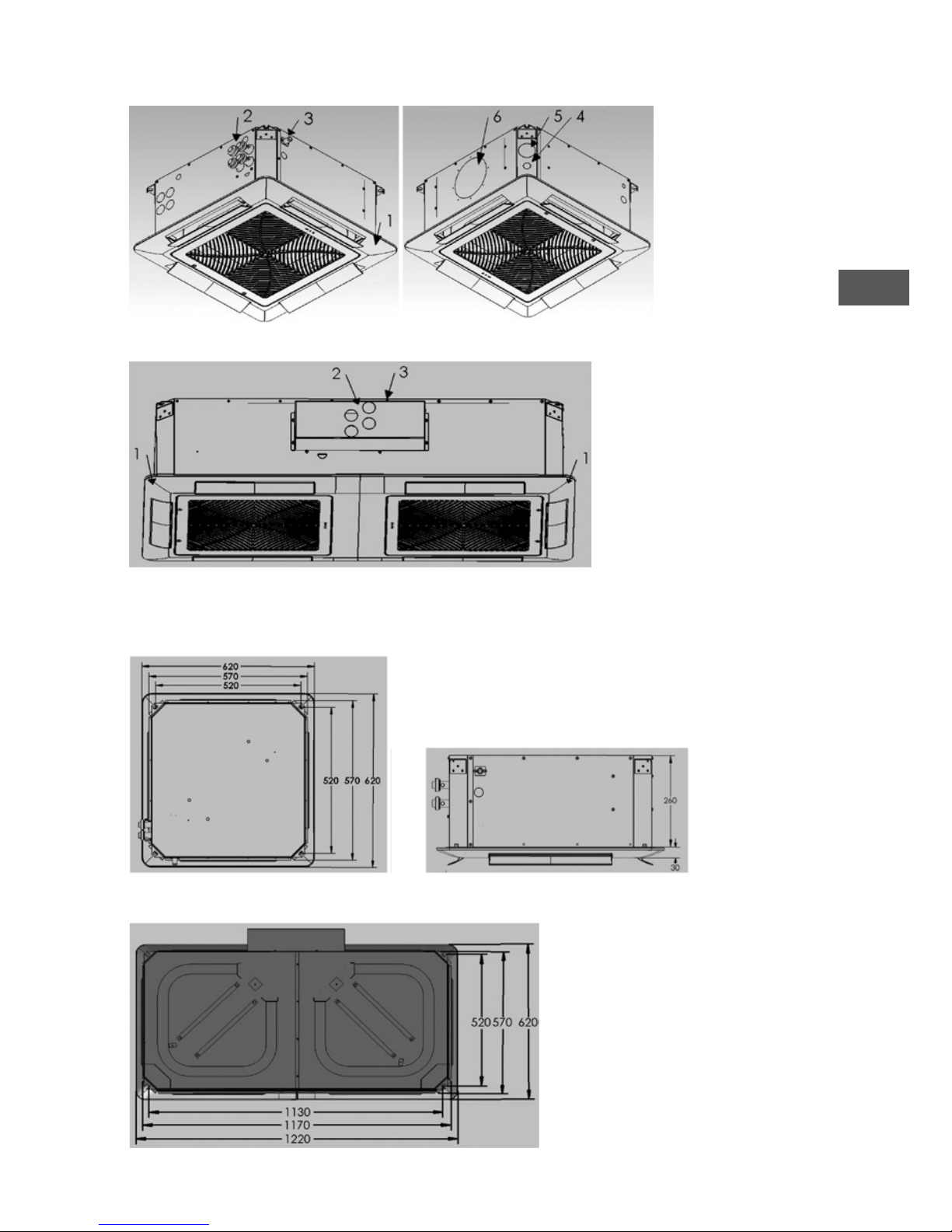
UNIT DESCRIPTION AND DIMENSION
OPERATING LIMITS
1 Frontal panel
2 Hydraulic connections
3 Condensate drain Ø16
4 Power supply wires input
5 Fresh air Ø60 mm
6 Distribution air Ø150 mm
TYPE 150/154
TYPE 150/154
TYPE 070/090/094
TYPE 070/090/094
Page 4

4
WASHER
NUT
Installation
- Fix the unit on a ceiling or a solid support without vibrations.
- Do not install the appliance in a space exposed to sunlight or heat sources, vapor or
ammable gas.
- Install the cassette so that the inlet and outlet air ducts are not obstructed; the air must
circulate freely throughout the area that has to be air-conditioned.
- Install the unit in an easily accessible location, not to hinder the maintenance operations.
UNIT FIXING
The location of the cassette installation must be chosen so that all around the unit
perimeter there is a space of at least 100 cm existing system (electrical or hydraulic). The
machine must be xed to the ceiling by the means of threaded rods with anchors adjusted
according to the type of structure (to be provided by others) as described:
- the 4 hole positions in the structural ceiling must rst be marked and the holes for the
threaded rods must then be drilled (the dimensions are show by g. A );
- the threaded rods must be securely xed in the ceiling (their lenght depends on the
distance between the ceiling and the structural ceiling);
- the unit must be lifted inserting the threaded rods in correspondence with the xing
slots and then blocked, using adequate washers and nuts (the arrangement is shown in
g. B);
- verify, using a spirit level, that the machine is perfectly horizontal and then x the nuts
and locknuts.
WASHER
NUT
TYPE 150/154
TYPE 070/090/094
Fig. B
Fig. B
Fig. A
Fig. A
Page 5

EN
5
PANEL FIXING
Fixed tightly the unit, the plastic panel must be mounted using only and exclusively the
screws provided (holes position in Fig. C)
To prevent the deformation of the grid, be careful not to overtighten the screws.
RENEWAL SYSTEM AND REMOTE AIR DISTRIBUTION
The side openings allow the separate realization of an external air intake duct for the
renewal and of an air hose duct for an adjacent room.
FRESH AIR
Remove the lm on the sheet indicated with letter A in Fig. D.
Use the ange Ø60 mm (optional) and connect the pipe with anti-condensate insulation;
the use of a fan for the duct (optional) must be provided with non-return valve and lter to
prevent dust.
REMOTE AIR DISTRIBUTION
Remove the lm on the sheet indicated with letter B in Fig. D.
Use the ange Ø150 mm (optional) and connect the pipe for air distribution in the
adjacdent room.
It is recommended the closing of the air vent on the panel in correspondence of the duct
of remote air distribution.
Fig. C
Page 6

6
HYDRAULIC CONNECTIONS
A correct installation provides also the anti-condensate insulation of the water pipes.
Always use adequate keys to avoid the damage of the connections.
The disposition of the water connections for the 2-pipes cassette is reported in g. E,
while the one for the 4-pipes cassette is reported in g. F.
CONDENSATE DRAIN CONNECTIONS
For its proper functioning, it is recommended to x the condensate drain duct with a
minimum slope of 2 cm/m.
Remember also that the maximum head of the pump is of 100 cm from the bottom edge of
the unit. (Fig. G)
Any condensate loss because of an incorrect connection of the drain is not
attributable to the manufacturer.
TYPE 150
TYPE 070/090
Fig. E
Fig. E
Fig. F
Fig. F
TYPE 094
TYPE 154
Page 7

EN
7
ELECTRICAL CONNECTIONS
The electrical connections must be performed by specialists, according to the
National electrical standards in force.
Before making any connection the power must be turned off.
Use the appropriate wire gauge to the maximum drawn current as shown on the label of
the technical data on the unit.
Insert the wires from the grommet, placed in the corner of the structure, and lay them up
to the terminal as described in Fig. 1.
VALVES CONDENSATE TRAY MOUNTING (optional)
The auxiliary tray collects the condensate formed near the water connections and the
valves.
Fix the tray to the structure with the screws provided in the position shown in Fig. H.,
making sure pipes and insulation do not tilt it, hindering the drain.
TYPE 150/154
TYPE 150/154
TYPE 070/090/094
TYPE 070/090/094
Fig. H
Fig. H
Fig. I
Connect respecting the instructions given in the scheme attached, according to the unit
typology and accessoires.
After the wiring, the wires must be securely xed to the structure to prevent any snag
during the maintenance operations to adjacent devices.
The incorrect connection and/or the failure to respect the National regulations
void the guarantee and any other responsibility of the manufacturer.
Page 8

8
CLEANING AND MAINTENANCE
Before maintenance, make sure the power of the unit is turned off.
Only qualied specialists can intervene.
The only component of the cassette that needs cleaning and maintenance is the lter,
placed on the air intake (unless there is the breakage of other components).
The lter must be cleaned with every season change, using a vacuum-cleaner or brushing it.
To perform this operation, follow the steps below:
- With the help of a at-blade screwdriver rotate of 90º the locks placed on the intake grid
of the front panel as shown in Fig. L.;
- remove the lter from the inner rails, being careful not to break them as shown in Fig.
M.;
- Once cleaned, re-insert the lter into the guide and close the grid by turning the locks of
90º in the opposite way than the opening.
- always reassemble the lter after cleaning it before restarting the cassette.
Page 9

EN
9
MALFUNCTIONS AND CORRECTIVE ACTIONS
FAN DOES NOT RUN
CORRECTIVE ACTIONS
- make sure that the machine is powered;
- check if some switches or fuses are;
- check the correct wiring of the unit (qualied personnel only)
- check if the thermostat is set in the right way.
LOW AIR FLOW
CORRECTIVE ACTIONS
- select an higher fan speed;
- replace or clean the lter.
THE APPLIANCE LEAKS WATER
CORRECTIVE ACTIONS:
- monitor and improve the insulation of the water pipes;
- tighten the water attacks;
- x the unit perfectly horizontally;
- clean the dip tray;
- check and clean the pipe of the condensate drain;
- monitor the proper functioning of the condensate drain pump;
- check the slope of the condensate collection tray.
THE UNIT DOES NOT COOL/HEAT
CORRECTIVE ACTIONS:
- lower/raise the set temperature on the thermostat;
- check that the chiller/boiler and circulation pump are turned on;
- bleed the water pipes;
- check if the thermostat is not installed in a warmer/cooler area;
- clean the air lter
All technical data and dimensions shown are subject to change without prior notice from
the manufacturer.
Page 10

10
ELECTRICAL DIAGRAMS
Page 11

EN
11
Page 12

MARK BV
BENEDEN VERLAAT 87-89
VEENDAM (NEDERLAND)
POSTBUS 13, 9640 AA VEENDAM
TELEFOON +31(0)598 656600
FAX +31 (0)598 624584
info@mark.nl
www.mark.nl
MARK EIRE BV
COOLEA, MACROOM
CO. CORK
P12 W660 (IRELAND)
PHONE +353 (0)26 45334
FAX +353 (0)26 45383
sales@markeire.com
www.markeire.com
MARK BELGIUM b.v.b.a.
ENERGIELAAN 12
2950 KAPELLEN
(BELGIË/BELGIQUE)
TELEFOON +32 (0)3 6669254
info@markbelgium.be
www.markbelgium.be
MARK DEUTSCHLAND GmbH
MAX-PLANCK-STRASSE 16
46446 EMMERICH AM RHEIN
(DEUTSCHLAND)
TELEFON +49 (0)2822 97728-0
TELEFAX +49 (0)2822 97728-10
info@mark.de
www.mark.de
MARK POLSKA Sp. z o.o
UL. JASNOGÓRSKA 27
42-202 CZĘSTOCHOWA (POLSKA)
PHONE +48 34 3683443
FAX +48 34 3683553
info@markpolska.pl
www.markpolska.pl
S.C. MARK ROMANIA S.R.L.
STR. KOS KAROLY NR. 1 A
540297 TARGU MURES
(ROMANIA)
TEL/FAX +40 (0)265-266.332
ofce@markromania.ro
www.markromania.ro
CERTIFICATION N°: 17.07.011
AIRSTREAM
CERTIFICATION N°: 17.07.011
AIRSTREAM
CERTIFICATION N°: 17.07.011
AIRSTREAM
 Loading...