

1

Quick User Guide ENC v.2
© Copyright by Marine Tech SA
All rights reserved.
Disclaimer
This document is protected by international copyright laws.
The content is proprietary to Marine Tech SA (“Marine Tech”), and no ownership rights are hereby transferred. No part of
this document shall be used, reproduced, translated, converted, adapted, stored in a retrieval system, communicated
or transmitted by any means, for any commercial purpose, including without limitation, sale, resale, license, rental or
lease, without the prior express written consent of Marine Tech.
Marine Tech makes no representations, warranties or guarantees, express or implied, as to the accuracy or
completeness of the manual. Users must be aware that updates and amendments will be made from time to time to
the manual. It is the user‘s responsibility to determine whether there have been any such updates or amendments.
Marine Tech nor any of their directors, officers, employees or agents shall be liable in contract, tort or in any other
manner whatsoever to any person for any loss, damage, injury, liability, cost or expense of any nature, including without
limitation incidental, special, direct or consequential damages arising out of or in connection with the use of the
manual.
Marine Tech accepts no liability for damages and/or injuries caused by improper use of the Seacraft ENC2 as well as a
result of its use in a manner contrary to or deviating from principles set out in this manual.
Marine Tech accepts no liability for accidents and damage resulting from incorrect use of the ENC2 resulting from
failure to read the ENC2 manual or lack of knowledge on the content of labels and pictograms, warning and
information signs.
2

This manual is no substitute for a proper training in how to dive and navigate under water, with or without
Title:
Quick User Guide Seacraft ENC2
Document Version:
1. 2 .2
Software Version:
1. 5
Publication Date:
3.04.2019
use of ENC2.
Should you have any questions or comments regarding this manual, please contact:
Manufacturer:
MARINE TECH SA
ul. Żwirki i W igury 17
38-400 Krosno , Poland
Email: info@seacraft.eu
Web: www.seacraft.eu
Document Information:
3

Table of Contents
1. Technical specifications ......................................................................................................... 6
2. Precautions ................................................................................................................................ 7
3. Mechanical construction ........................................................................................................ 8
4. Control ..................................................................................................................................... 9
5. Main screen layout .................................................................................................................. 11
6. Additional information screen (next to main) ................................................................ 16
7. Destination parameters – setting and changing ........................................................... 20
8. MENU screen ........................................................................................................................ 24
9. Depth profile graph ............................................................................................................... 27
10 . Swim route graph ............................................................................................................... 28
11. TIMER / stopwatch .............................................................................................................. 29
12 . Device configuration (SETUP) ......................................................................................... 30
13 . Send data .............................................................................................................................. 30
14 . Pressure/salinity ................................................................................................................... 31
15 . Log/speed .............................................................................................................................. 32
16 . Log/speed calibration ........................................................................................................ 34
17 . GPS .......................................................................................................................................... 36
18 . Time/date .............................................................................................................................. 37
19 . Other settings ...................................................................................................................... 38
4

20. Units ....................................................................................................................................... 39
2 1. Compass ............................................................................................................................... 40
22. Clear data ............................................................................................................................. 44
23. Factory reset ....................................................................................................................... 44
24. Exit ......................................................................................................................................... 44
25. Guidelines for attaching the ENC to DPVs ................................................................... 45
26. Troubleshooting ..................................................................................................................47
27. Before each dive … ............................................................................................................. 49
5

1. Technical specifications
Model ENC II Power source Built-in Li-ion 3,7V battery
Type ENC v.2 Battery capacity 5Wh
Maximum depth 300 m Typical working time 20-35 h
Tested depth 350 m Average charge time < 2 h
Depth of start and stop of
immersion time counting
Accuracy of depth
measurement
Accuracy of compass 5 degrees* Temperature when charging +10 … +40 ⁰C
Accuracy of ext. log 2%* Mounting type Universal
Possibility of using above
the water level
Weight / displacement 290 g / -90g Length x height x width 95 x 71 x 30,6mm
* The accuracy of the measurement depends on the quality of the calibration and the absence of external interference.
Included sensors: 3D magnetometer, 3D gyroscope, 3D accelerometer, pressure sensor, temperature sensor.
Satellite positioning: GPS, Beidou, GLONASS
Optional: 0.5, 1 or 1. 6 m
(compatible with the norm
E N 13 3 19 )
0.3m in the whole depth
range, temp. range: 0…30°C
up to 5000m Internal storage capacity 50 routes
Working temperature +10 … +45 ⁰C
Storage temperature -20 … + 4 5 ⁰C
Data exchange: via Bluetooth 4.2. Temperature range: 0 … 40°C
Power source: Li-Ion battery cell 5 W h. Device can use any 5V DC power source as charger. When charging, it can
consume up to 1A current.
6
2. Precautions
WARNING !
This device may have some bugs in the software, which we did not find yet.
Waste disposal information:
This manual is suitable for the navigation device with software version 1.5.04 t o 1. 5. 0 9 . the Software version number is
shown under MENU, when the battery voltage is displayed (OFF option selected).
You should never risk your life using this device as sole advisor.
Electronic devices are designed for support and cannot substitute knowledge and
training.
This device contains Li-Ion cells and other materials, which must be recycled properly.
7
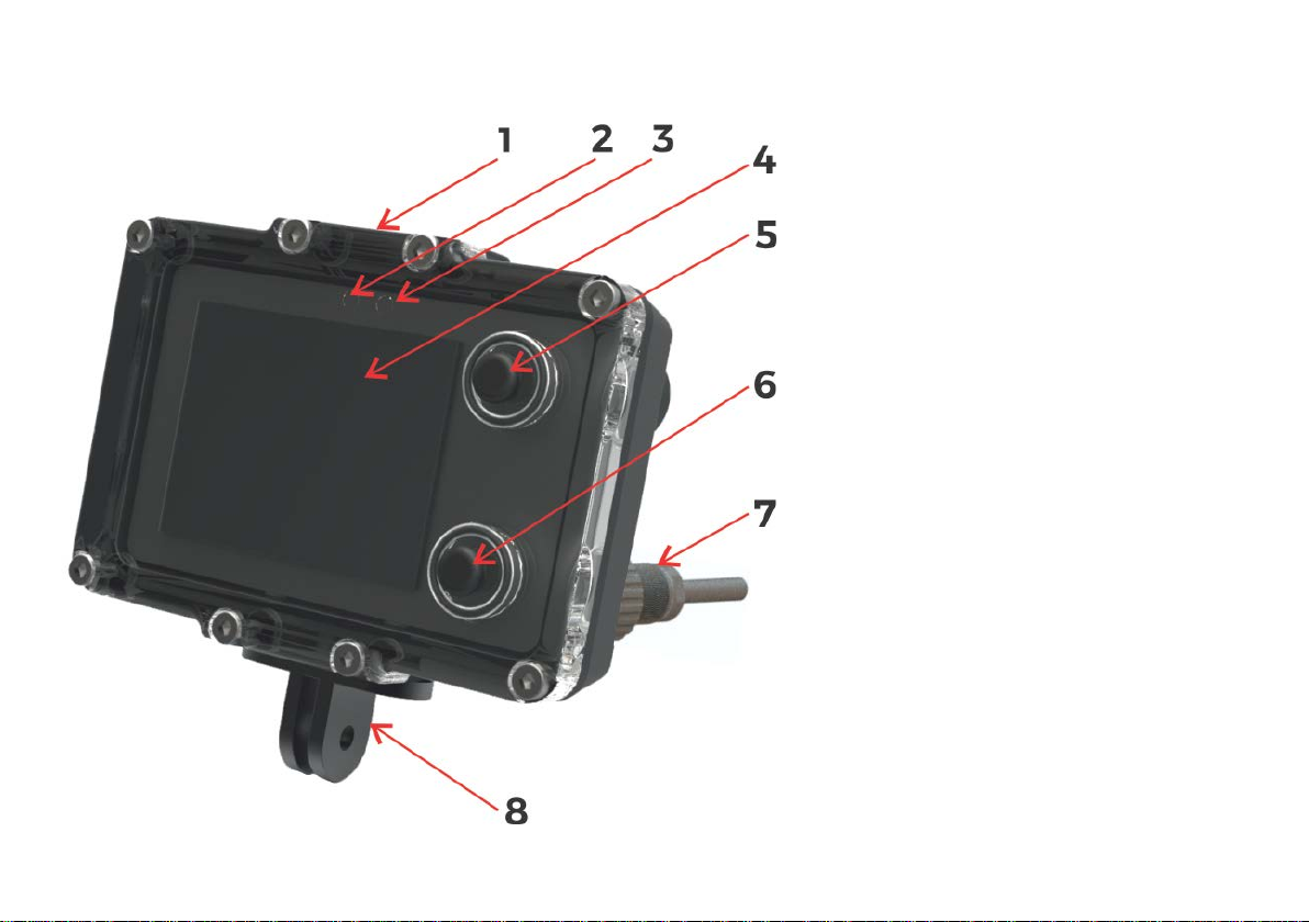
3. Mechanical construction
Fig . 1. Description of elements.
1. Universal mounting – top side
2. Ambient light sensor (do not cover)
3. Additional LED diode (red color)
4. Screen / display
5. Top button (NEXT)
6. Bottom button (SET, REC, HOLD)
7. External socket – for charging and
speed sensor
8. Universal mounting – bottom side
8

4. Control
- Move cursor/selection down to next item
- Go to next screen
- Go to previous screen
- Select current item
X
- Cancel or delete
>>
- Switch to next available value
+
- Increment current value by 1
Button functions (depending on actual screen content):
Top button (5) – NEXT screen, NEXT item, CANCEL change, BACK
Bottom button (6) – SET, change value, enter changing item, switch REC/HOLD
Note
On most screens, a small graphical hint is displayed in top and bottom right corner of the display.
This hint is connected with the actual button function. It may be one of the below:
9

First steps - switching on and off:
Switching on the device – press both buttons at the same time.
The device will also switch on when immersed in water min. 0.3 m ( 1 f t ) deep.
Switching off the device – You have to stop recording first. Then go to MENU (from main screen –press the top button 3
times, then press the bottom button once). When the OFF command is selected, press the lower button.
The device will switch off automatically when the diving depth is less than 0.5 m and recording is off (HOLD).
Modes of operation:
Normal operation mode – Default mode after power on. The user sees the current dive parameters, may switch
recording ON (REC) and OFF (HOLD), enter settings and view the contents of the device’s internal memory.
Charging mode – After connecting the device to a power source, the charging screen appears. The buttons are inactive
in this mode. This mode will be terminated, when the battery is fully charged or the power source is disconnected.
Service mode – When a software update was requested, the device switches to this mode. The screen is blank and the
LED above the display is blinking. This mode ends automatically after less than 3 minutes.
10
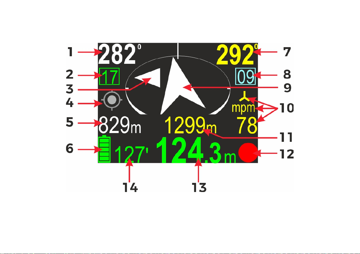
5. Main screen layout
After power on, the device display will show this content:
11
Screen elements:
1. Course to planned destination. If no destination is
These values alternate
Current compass heading (including programmed
8. Present marker number. For using markers, please see
planned destination. If no destination is
should be connected to get valid distance/speed
RECORD
programmed, this field is blank.
2. Present memory slot number. If you start recording,
the dive data will be saved in the device memory with
this number.
3. Small deviation marker (described below).
4. GPS state marker (described below).
5. Time/distancer to destination.
every 3 seconds. This field may be blank, if the
corresponding value cannot be calculated.
6. Battery icon, and to the right the total dive time in
minutes.
7.
deviation).
next chapter.
9. Destination direction arrow. The tip of the arrow is always
pointing to the
set, this arrow will not move.
10 . Present speed value and units. mpm means that the
speed is displayed in meters per minute, kts stands for
‘knots’. The symbol
means, that the external speed
sensor
readings.
11. Total distance travelled.
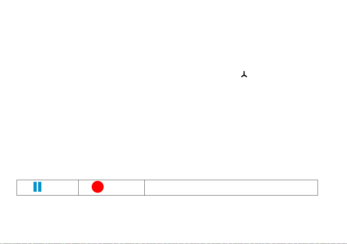
12 . REC/HOLD marker.
13 . Present dept.
14 . Total Dive time.
Buttons role:
Top button – Switch to next screen
Bottom button – Switch recording between ON (RECORD state) and OFF (HOLD state). The icon in the right bottom
corner shows the current recording state as described below.
HOLD
REC/HOLD marker
NO TE - When the device is in RECORD state, the red dot symbol is animated.
12
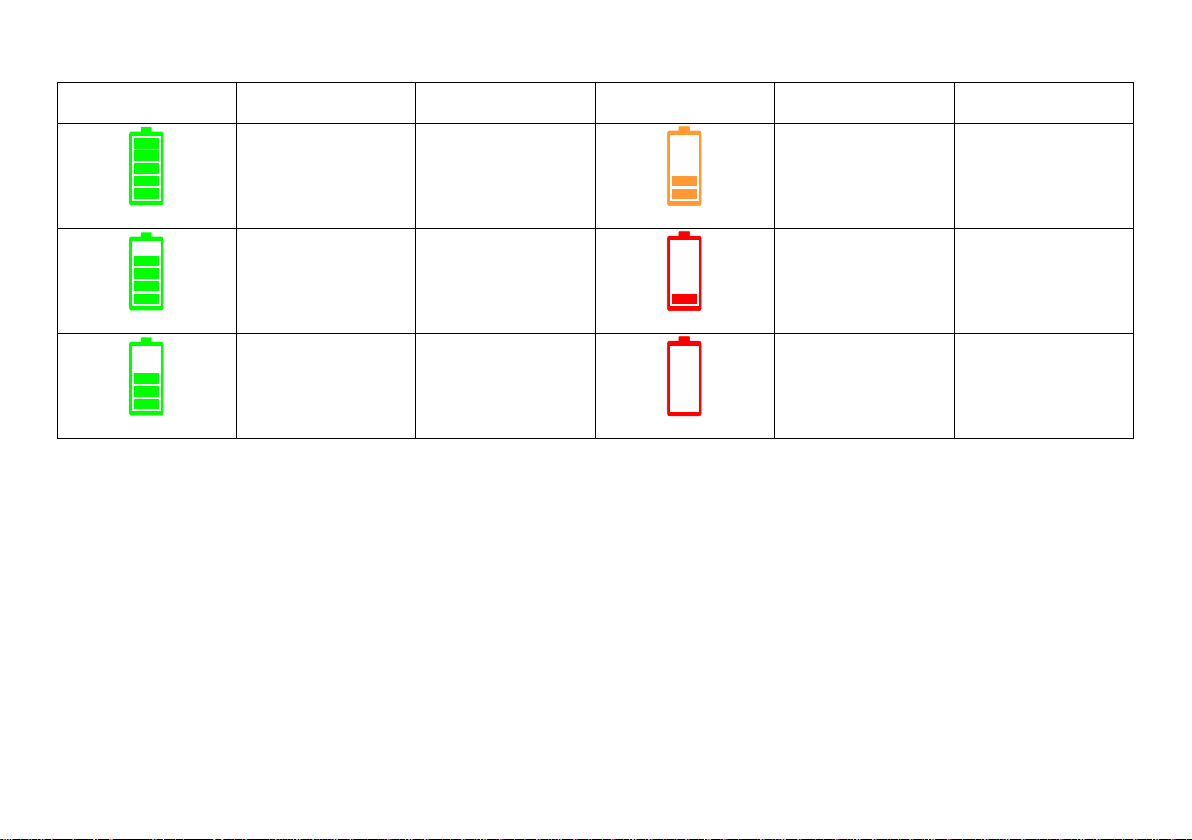
Battery indicator
Icon
Charge on %
Time left
Icon
Charge in %
Time left
85-10 0 20-25h
68-84 17 -20h
46-67 10-17 h
Caution: The value ‘Time left’ is approximate!
28-45 5-10h
12 -27 1-5h
1-11 <1h
13
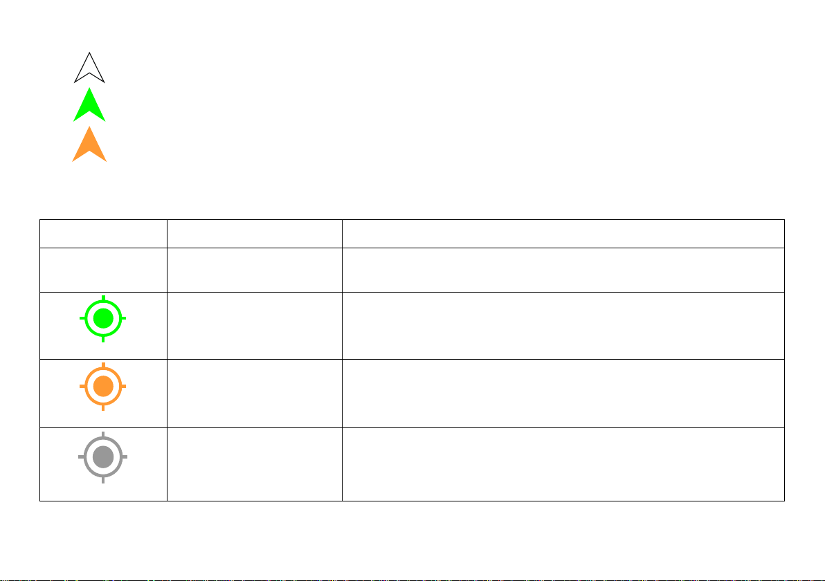
Navigation arrow colors:
Icon
Meaning
More info
The Navigation device does not include a GPS receiver or it has been
White – Normal operation with or without programmed destination
Green – Destination is set and distance to it is less than 10 meters
Orange – The diver is returning to the start point (distance >10 meters)
GPS indicator:
(no icon) No GPS available
GPS location fixed
GPS location fixed
GPS readings are available, but the accuracy may vary
No valid GP S location
available
The GPS receiver cannot obtain the current location,
but previous readings may be still available and valid.
14
permanently disabled.
Good GPS readings are available.
The GPS location is valid and accurate.
due low signal strength/quality.

Depth indicator colors:
Color
Meaning
More info
0.0
9.5
24.3
The user should be aware, that ascending or
Vertical speed (up or down) is less
than 9m/min (29.5 ft/min)
Vertical speed (up or down) is equal
or greater than 9m/min (29.5 ft/min)
Vertical speed (up or down) is equal
or greater than 19m/min (62.3 ft/min)
The vertical speed is calculated based on measurements taken in the last 3 seconds.
No special actions required from diver.
There is a noticeable depth change.
descending at this speed may have negative health
effects.
15

6. Additional information screen (next to main)
1 - Course to the programmed destination
parameters
7 - Top button role – go to the next (lower)
After pressing the top button on the main navigation screen, the display content changes like shown above.
On the left side of the screen, all present information are shown. On the right side there is a list with all available
options. The currently selected item is marked by inverting the background and foreground color (highlighting).
In the picture above, first item (DESTIN) is selected, so left part of the display is filled with information connected to
actual destination parameters:
2 - Time left to destination (approx.)
3 - Distance left to destination
4 - Current record number in memory / maximum available
records
5 - GPS information: available satellites count / horizontal
Note: If some of parameters cannot be evaluated, a ‘---‘ value will be shown instead.
precision
6 - Operation hint – when you press the lower button, you will
be redirected to the screen with DESTINATION
item
8 - Currently selected item
9 - Bottom button role – enter/choose the
selected item
16
Buttons role:
Top button – Select the NEXT item. After 3
rd
press, you will return to the main navigation screen.
Bottom button – ENTER to activate the selected item.
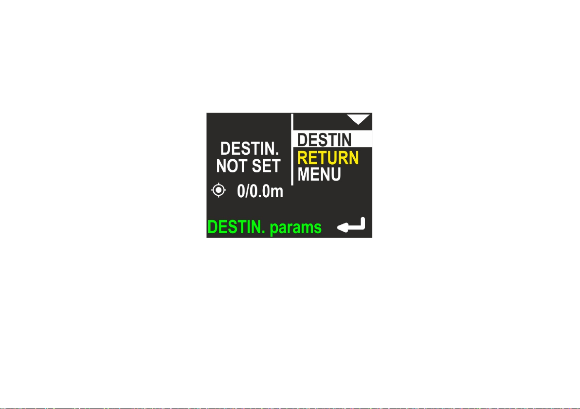
Note: If the destination parameters are cleared (not set), this screen looks like this:
17
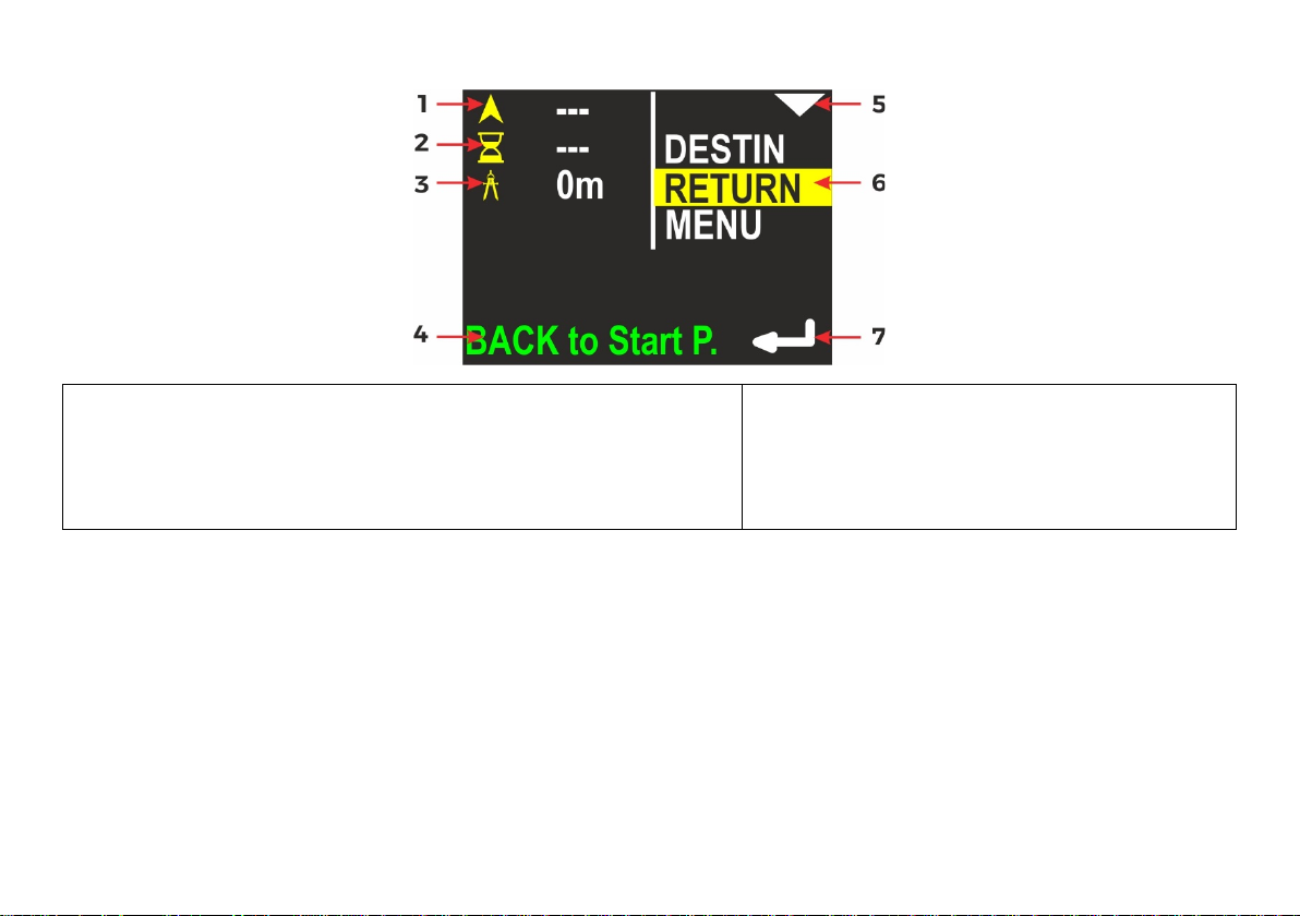
If the RETURN item is selected, the screen looks like this:
1 - The course you need to follow in order to return to the
device will guide you back to the start point
5 - Top button role – go to next (lower)
start point
2 - The time required to return to the start point (approx.)
3 - The distance from current location to the start point
4 - Operation hint – when you press the lower button, the
item
6 - Currently selected item
7 - Bottom button role – enter/activate the
selected item
Buttons role:
Top button – Select the NEXT item (MENU).
Bottom button – Switch the device from navigating to DESTINATION to navigating back to the START POINT.
18
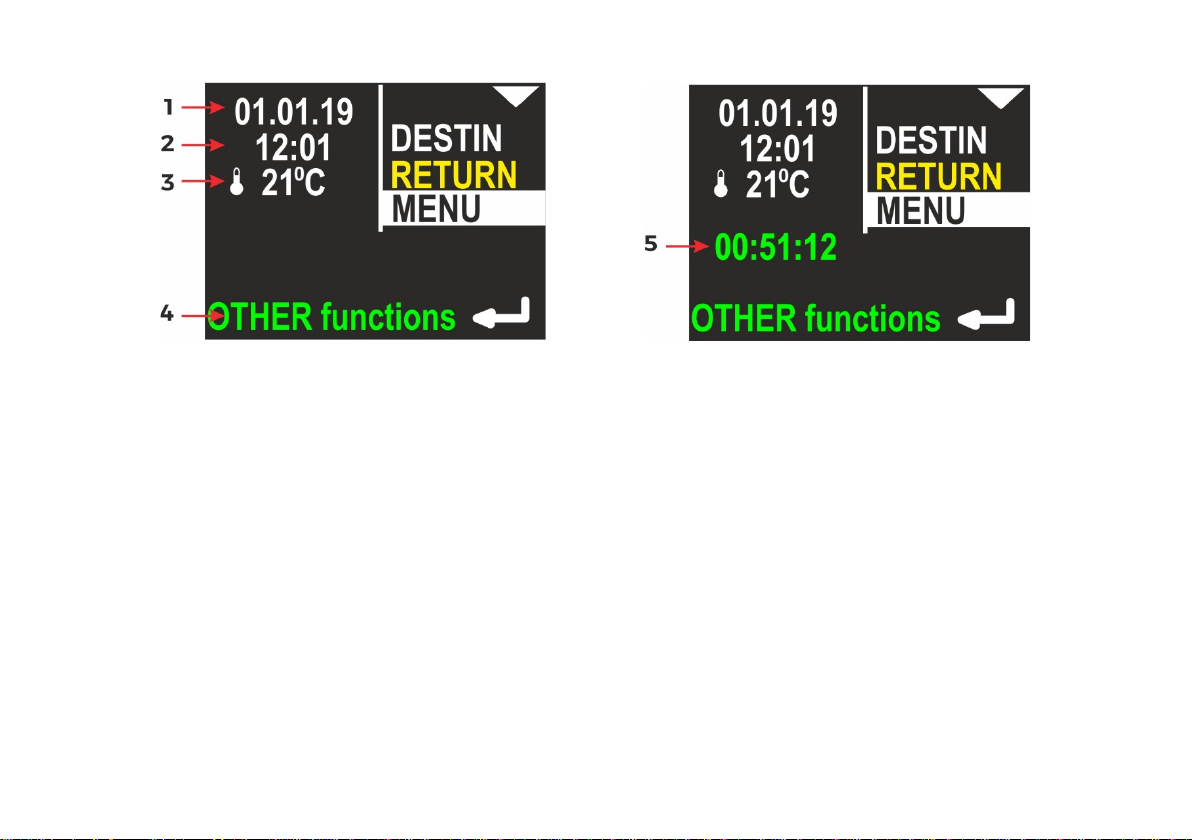
If the MENU item is selected, the screen looks like this:
1 - Internal date (DD.MM.YY)
2 - Internal time (hh:mm), in 24-hour system
3 - Water temperature
4 - Operation hint – when you press the lower button, other functions will be shown.
5 - Stopwatch
The description regarding the right display side is the same as on previous picture.
Note: If the STOPWATCH is running or was stopped with count > 0, the STOPWATCH value will also be shown in green
color on this screen (see below).
19
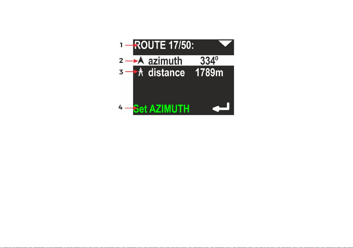
7. Destination parameters – setting and changing
When you activate the DESTIN(ation) option on the additional information screen (see f i g . 1 o n p. 6), the device will
show the current destination parameters (if set) or it will suggest new ones, as shown in the following picture:
1 - Current route number in memory / total routes in memory
2 - Azimuth – planned course (including deviation)
3 - Distance – The distance to the planned destination
4 - Operation hint – When you press the lower button, AZIMUTH can be modified.
20

If you press the lower button (ENTER) when azimuth is selected, the display will change like this:
You may now rotate the device, in order to set the desired heading. Then simply press the lower button (ENTER), if the
value is appropriate. You may also press the upper button now. This will allow you to set the desired azimuth manually
digit by digit (use the lower button to change the value).
21
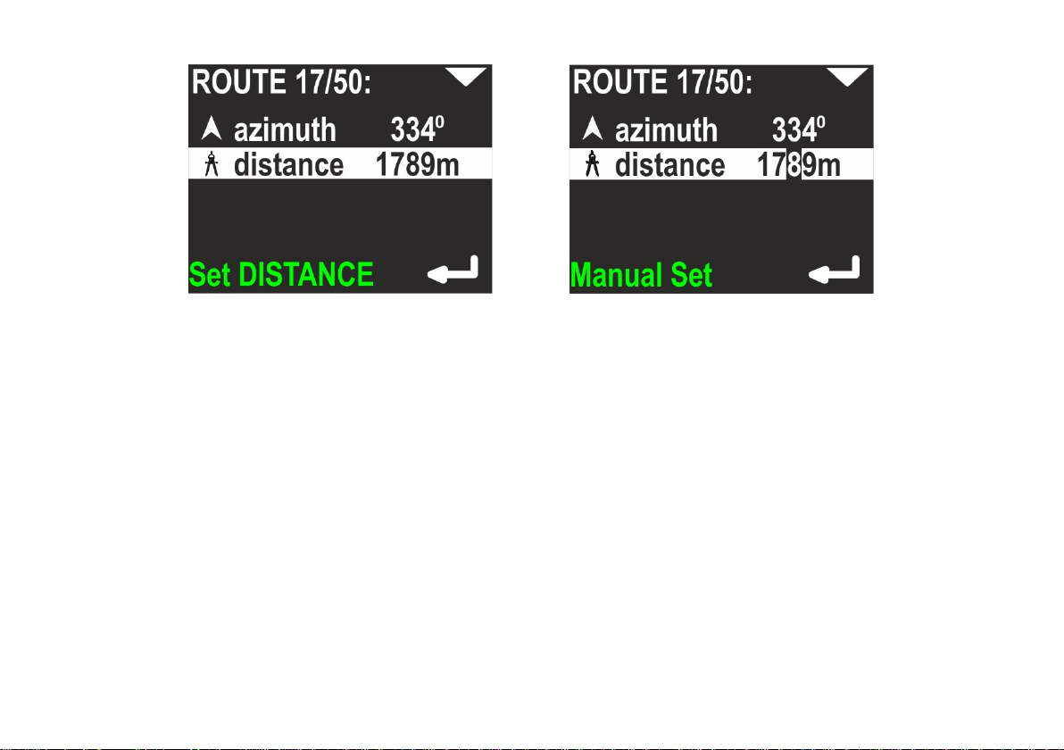
Next, set the distance – you may do it when the second line is highlighted:
Distance value is changed also digit by digit. Pressing the top button switches to the next position, the bottom button
changes the value
0 > 1 > 2 > … > 9 > 0.
Note: The minimal allowed distance is 10m (or 0.01 mile). The device will not allow to set a shorter distance.
22
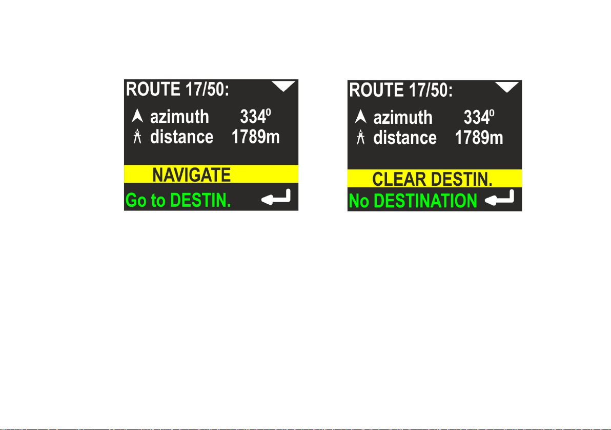
When both parameters (azimuth and distance) are set, pressing the top button will bring up the command line.
You may choose from two commands, using the top button:
NAVIGATE – Apply values and switch to main screen (with destination)
CLEAR DESTIN(ation) – Clear all values and switch to main screen (without destination)
Note:
- The DESTINATION, once set, is held in memory until cleared or changed (power off will not clear it).
- The DESTINATION is always set or changed relatively to the current position.
23
8. MENU screen
If you press the lower button (ENTER) when the MENU item is highlighted on the additional information screen (see fig.
1 on p. 6), you may choose between 4 commands:
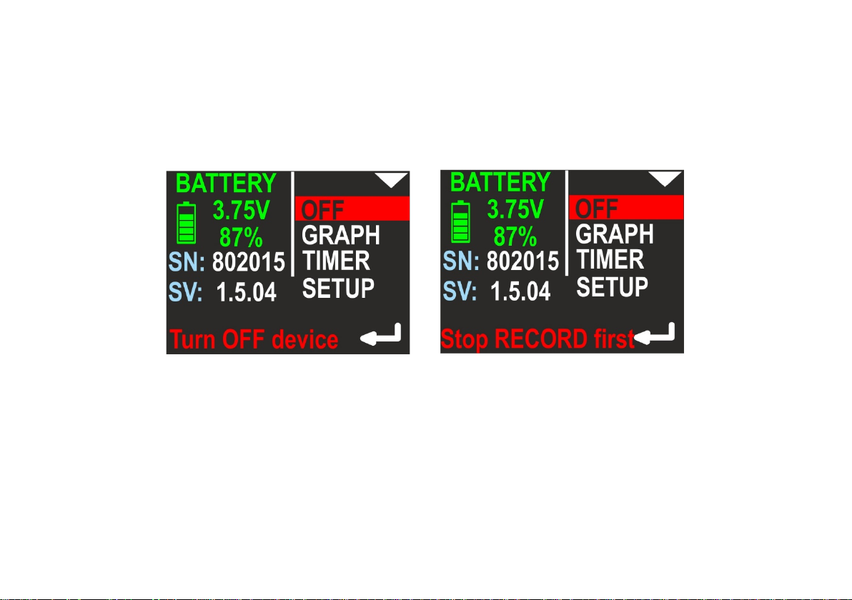
OFF – Allows you to switch off the device. The left part of the screen shows information about the present battery
charge. Below that you see the device serial number (SN) (unique device identifier) and the internal software version
(SV), as illustrated below:
Note: You cannot switch off the device in the recording state (Hint: Stop RECORD first in bottom line – right picture).
This prevents the user from accidentally switching-off the device.
24
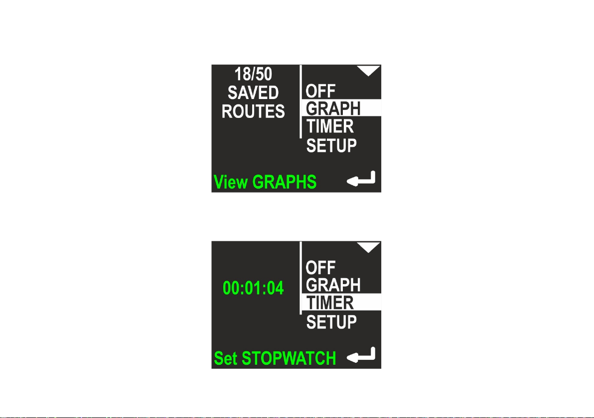
GRAP H – Allows you to show the position and depth graphs on the device screen. More info about graphs can be found
in chapter 9 and 10. On the left side of the screen, the device shows 2 numbers: Current routes in memory / maximum
routes in memory. More about memory organization can be found in chapters 9 and 10.
TIMER – Allows you to start, stop and clear the internal stopwatch. The stopwatch is described in chapter 11.
25

SETUP – This allows you to show and change all internal configuration parameters. More about this function can be
found in chapter 12. On the left side on the screen, the most important settings are shown in short form (to avoid
unnecessary activation of the configuration just to check it).
26

9. Depth profile graph
If you press the lower button (ENTER), when the GRAPH item on the MENU screen is highlighted, you will
be redirected to the simple graph browser. The first available graph is called ‘depth profile’ and contains a
representation of dive depth vs time, as shown below:
1 - Top button role (now – go to next graph: swim route graph)
2 - Time of first recorded data (hh:mm, 24-hour system)
3 - Date of first recorded data (DD.MM / YYYY)
4 - Average depth (if it can be evaluated)
5 - Maximum depth (if it can be evaluated)
6 - Route number in memory (blue) and lower button role (now – go to the next route number)
Note:
– The internal device memory stores all dive data identified by ‘route number’. When the device is
switched on, the least available (empty) route number is chosen for recording current data. If all
available route numbers (1-50) are used, the oldest one will be overwritten.
– Data recording can be paused (HOLD state). The graph above does not show these breaks.
– You may tilt device to left or right to change the button roles on this screen. When tilted left, the lower
button switches to the previous route number. When tilted right, the lower button will allow you to
delete the current route.
– If the recording time is less than 1 minute, the record will be deleted when the device is switched off.
27

10 . Swim route graph
This screen presents the changes in the diver location projected on a flat surface (like on a map). The route start point is
always positioned in the screen center. The route end point will be shown as a green dot, but only on the present route.
Near the right edge of the screen, you will find some information elements:
1 - Top button role (now – go to next screen: return to main menu)
2 - Time of first recorded data (hh:mm, 24-hour system)
3 - Date of first recorded data (DD.MM / YYYY)
4 - Total recording time, in minutes (above 2h, this value will be shown in hours), may be blank, if the value cannot
be calculated (empty record)
5 - Total distance in meters (above 2000m in kilometers), may be blank, if the value cannot be calculated (empty
record)
6 - Route number in memory (blue) and lower button role (now – go to the next route number)
Note: You may tilt the device to the left or to the right, in order to change the button roles on this screen. When tilted
left, the lower button brings you to previous route number. When tilted right, the lower button will allow you to delete
the current route. When tilted left, the upper button brings you to the previous graph (depth profile).
28

11. TIMER / stopwatch
If you press the lower button (ENTER) when the TIMER item on the MENU screen is highlighted, you will be redirected
to the TIMER/STOPWATCH control screen:
1 - EXIT – current selected command; if you press lower button (ENTER), you will return to main navigation screen
2 - Timer START – option to start TIMER/STOPWATCH for counting
3 - Current TIMER/STOPWATCH value (up to hh:mm:ss – hours: minutes: seconds)
4 - Timer STOP – option to stop TIMER/STOPWATCH
5 - Timer CLEAR – option to clear TIMER/STOPWATCH
If TIMER/STOPW ATCH is running, there will be options to STOP and CL EAR its value. STOP will leave the
TIMER/STOPWATCH value unchanged (you will be able to start it again and continue counting). CLEAR will set the
TIMER/STOPWATCH value to 00:00:00, but the stopwatch will not be automatically stopped with this command.
29

12 . Device configuration (SETUP)
If you press the lower button (ENTER) when the SETUP item on the MENU screen is highlighted, you will be redirected
to the SETUP menu. Device settings are organized in 2 screens. The selected function is highlighted. The top button
(NEXT) will switch the selected function to the next one (below). The bottom button (ENTER) will activate the selected
item.
Settings:
13 . Send data
Used to activate the internal Bluetooth transmitter. Activate it before any data transmission from the navigation device
to a PC or smartphone. When this function is activated, the device will not power off automatically (except when the
battery is low).
30

14 . Pressure/salinity
Shows the current pressure in milibar (green color). 1 P S I ≈ 68,95 milibar. When no pressure is shown, the pressure
sensor is defective.
The lower line shows the pressure correction (white color) – this value will be added to the raw value of the measured
pressure. It has no effect on depth calculations, but the value will be added to the pressure measurement shown above,
so the user may calibrate this device as a precision barometer.
The last line allows to set the water salinity from 0.0% (fresh water) to 4.0%. This coefficient affects the pressure-todepth transformation and should have an appropriate value.
When the item is highlighted, pressing lower button will allow to edit its value.
31
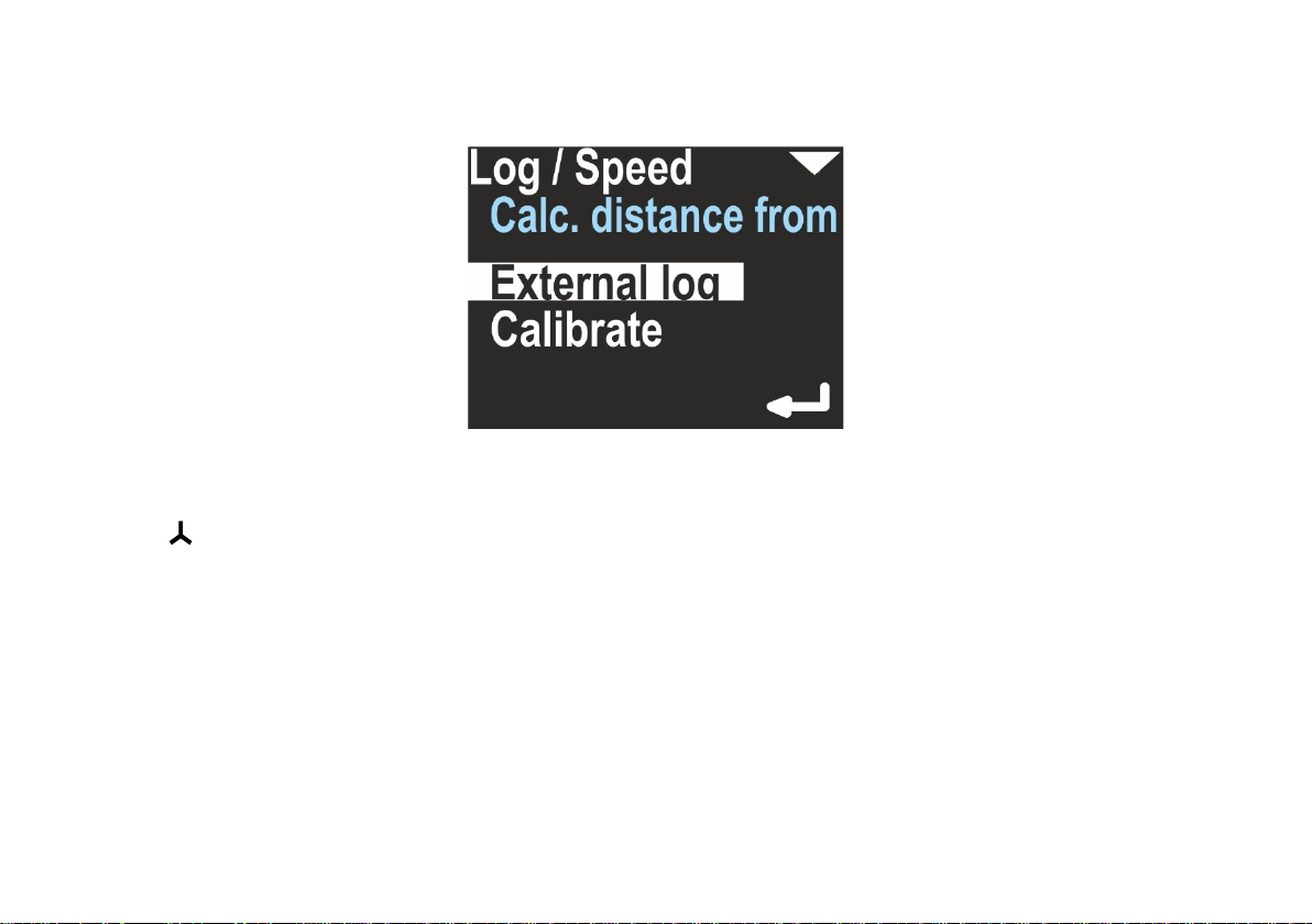
15 . Log/speed
This navigation console can work with an external sensor (speed sensor) or without it (inertial mode). This option can be
used to switch between these two modes.
The field ‘Calc. distance from’ may switch between ‘External log’ and ‘Const. speed’. The first value needs an external
speed sensor (log) to be connected. If chosen, on the right side of the main navigation screen, this icon will be
displayed:
The option ‘Calibrate’ may change its coefficient, which is used to convert sensor pulses into speed and distance:
32
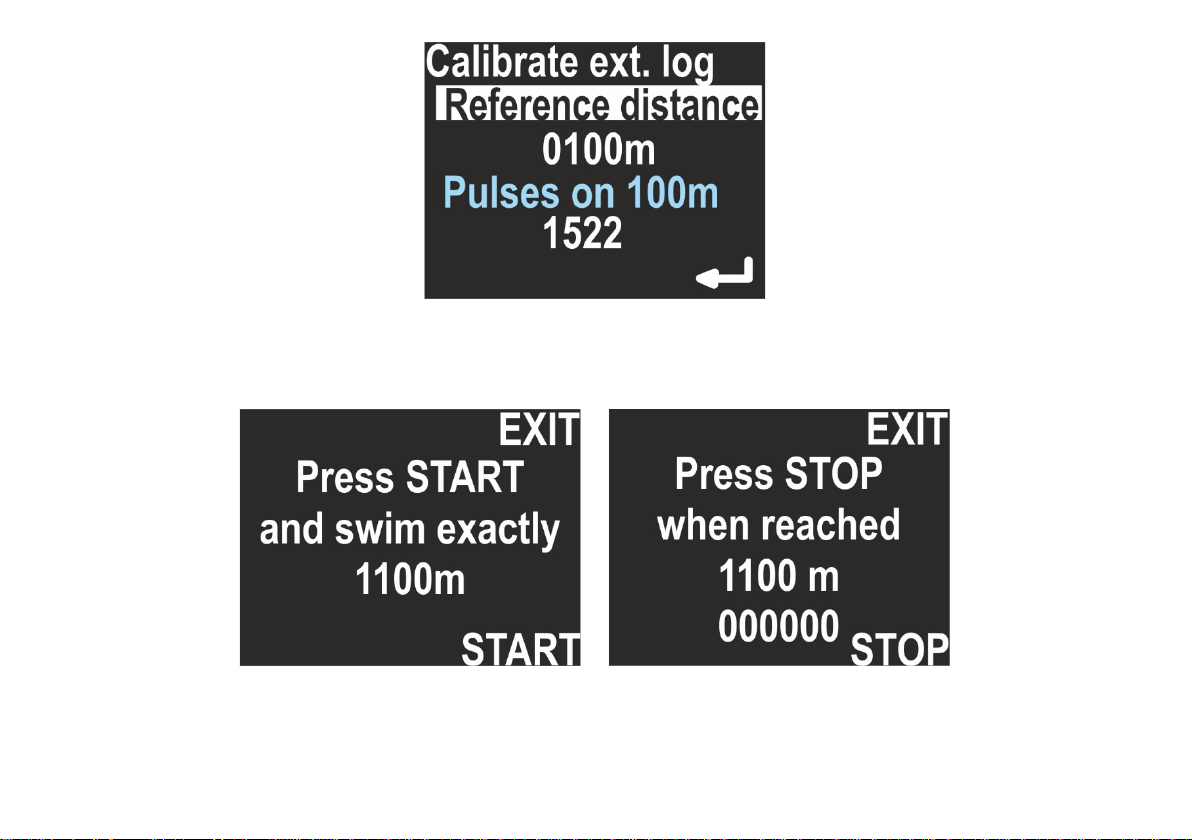
If you want to recalibrate the sensor, set the chosen distance in meters (reference distance) by pressing the lower
button and changing the value digit by digit. Then, you will be guided to the next item, which shows how many pulses
fall in a distance of 100m. By pressing the lower button again, a new calibration begins:
Press START and swim straight with no depth change, until the chosen distance is reached, then press STOP. The
display will show you, how many log pulses were counted. If no pulses were logged, the calibration will be rejected.
33
When ‘Calc. distance from’’ is set to ‘Const. speed’’, a constant average speed is chosen to calculate the position (on the
main screen, no log symbol is visible).
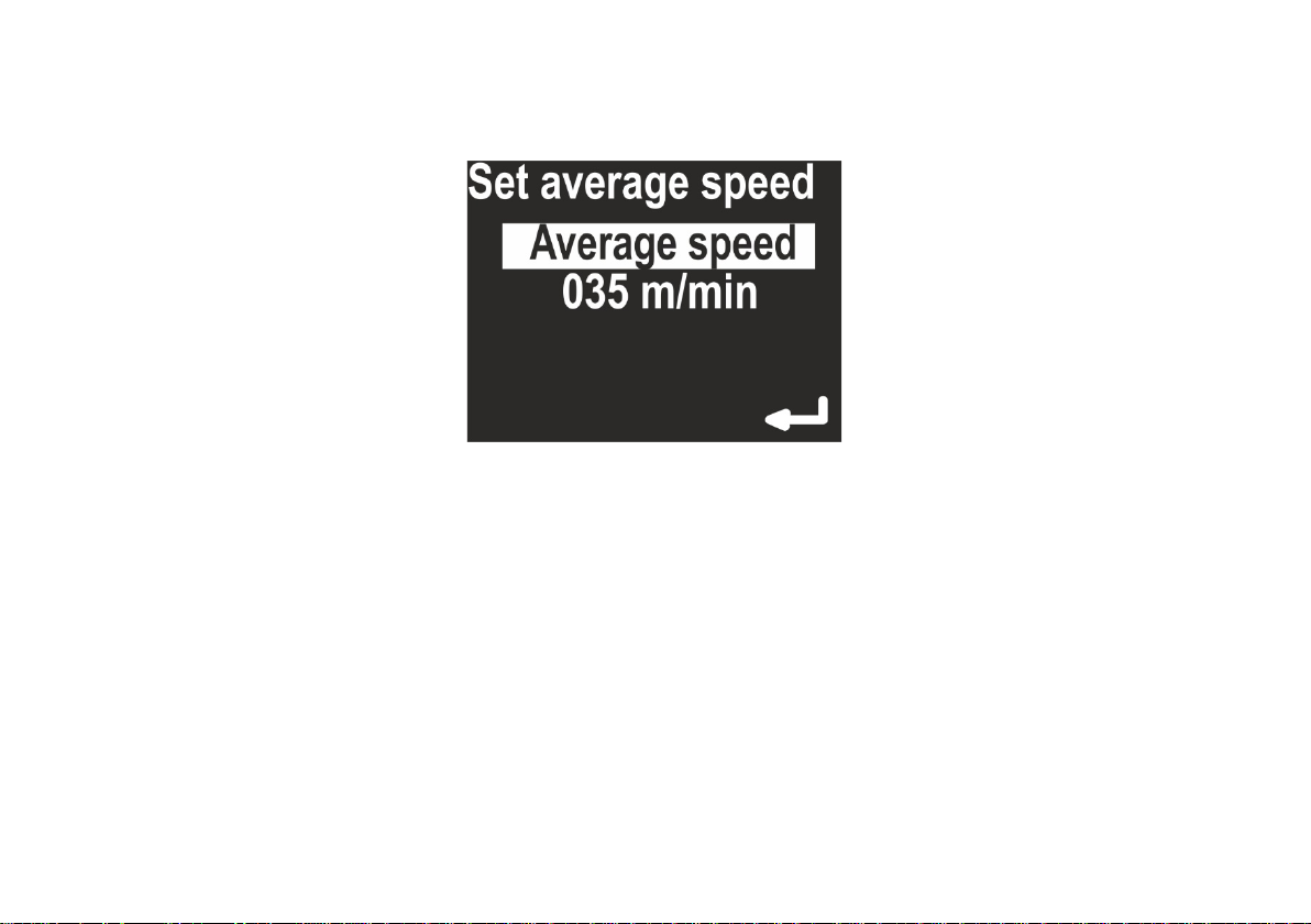
The option ‘Calibrate’ will allow you to set a constant average speed used to calculate the current position, the return
time and the target time.
16 . Log/speed calibration
ENC2 operation is different with and without external log sensor. Thus, the ‘Calibrate’ command has also different
meanings, depending of the actual sensor settings.
When the external sensor is not used (Calc. distance from = Const. speed), the calibration means to choose an average
swimming speed. When the device is in HOLD state, the distance counter does not change. When the user switches
the device to RECORD state, the navigation console expects the user to swim with constant speed equal to the value
set in this option (e. g. 50 m/min).
This type of operation requires from the user:
- Setting the average swim speed very precisely
- Swimming at constant speed
- Switching between HOLD and RECORD state as quick as possible
34

When the external sensor is used and connected to the device (Calc. distance from = External log ), the calibration is
used to get the best possible distance measurements. The sensor principle of operation is based on pulse counting.
The sensor calibration factor equals the number of pulses which the speed sensor will produce while swimming a 10 0 m
distance.
A typical value is 1490 pulses on a 10 0 m d i s t a n c e .
This calibration factor depends also on the sensor position on the DPV. To get best results, mark the sensor position on
the DPV body and perform the calibration procedure as described below:
- Mark the START and STOP point on a straight, known distance (100-1900 meters)
- Go to SETUP -> Log/Speed -> Calibrate log (make sure Active log is set to EXT )
- Enter the known calibration distance in the field log at: …
- Below, you will see the actual calibration factor log 100m: 1490. Make sure, the arrow points to this line, and
press the lower button.
- The screen will show the message Press START and swim exactly …. m
- Go to START, set the favorite speed on your DPV, press START (lower button) on the navigation console, and
swim as straight as possible to the STOP point. The screen display will show the pulse counter, which should
increase with time.
- When you reach the STOP point, press the lower button again. The new log calibration factor will be shown on
the screen.
Caution: The calibration procedure will fail, if the pulse count recorded during the procedure is far too low. In this case,
the previous value will be shown in the calibration factor field (log 100m: …. )
The calibration procedure needs values in meters. No other units are available. 1 N.M. (Nautical Mile, U.S.) equals 852.0
meters. 100 feet equals 30.48 meters. 100 meters equals 328.08 feet.
35

17 . GPS
This menu option is for information purposes only. When selected, the navigation screen will show the GPS status
information as described below:
- Valid: Y/N – Displays, if GPS information is available now
- Sat.cnt: 0 …15 – Number of satellites used to calculate the position
- Latt. N/S 0.00000° - Latitude in degrees, can be N(orth) or S(outh)
- Long. E/W 0.00000° - Longitude in degrees, can be E(ast) or W(est)
- Alt. 0.0 – Altitude, meters above sea level
- D 0.0 – Horizontal deviation, always in meters (the lower, the better)
Note: When Valid is set to N, other values can be 0 (if no valid, GPS readings were obtained during the last 30 seconds)
or the value might display the last valid readings. When Valid is set to Y, values equal the present reading.
GPS information is refreshed automatically after each successful update on this screen.
The GPS state is also reported as icon
The GPS receiver is automatically switched off, when the water depth is 1.5 m (4.9 ft) or more, in order to save battery.
When the water depth is 0.5 m or less (1.6 ft), the GPS receiver is switched on automatically.
on the main screen in NAVIGATION and SIMPLE mode.
36
After power on, first GPS readings should be available after 20-60 seconds. The GPS antenna is located between the
buttons, so you should not cover this point with any objects.
You may tilt the navigation console as far as possible (screen upwards) for a while, to achieve better/quicker GPS
readings, but this is not necessary in most cases.
18 . Time/date
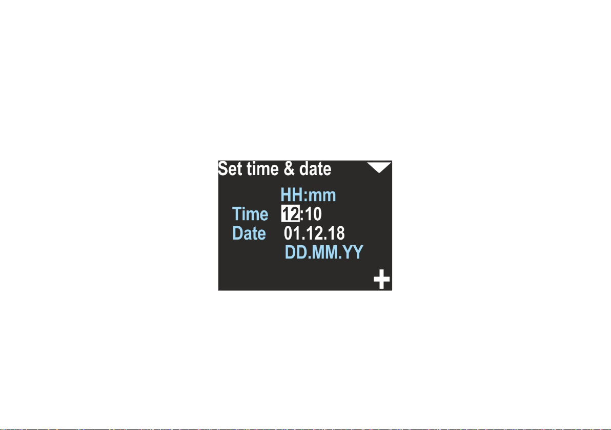
This device provides an internal real time clock with calendar.
The time format is 24 hours, the Date format is DAY.MONTH.YEAR. YEAR has only 2 digits. The value 01 means the year
2001, 02 means 2002 and so on.
Caution:
– The device may drop date & time settings, if the battery was discharged too much. If this happenes, the first step
after choosing the desired mode will be setting date/time. You may skip this option, and the console will not ask you
again for it, but your records will have an improper timestamp.
- The device clock accuracy is about 15 seconds per month. You may need to correct date & time settings from time to
time.
37
19 . Other settings
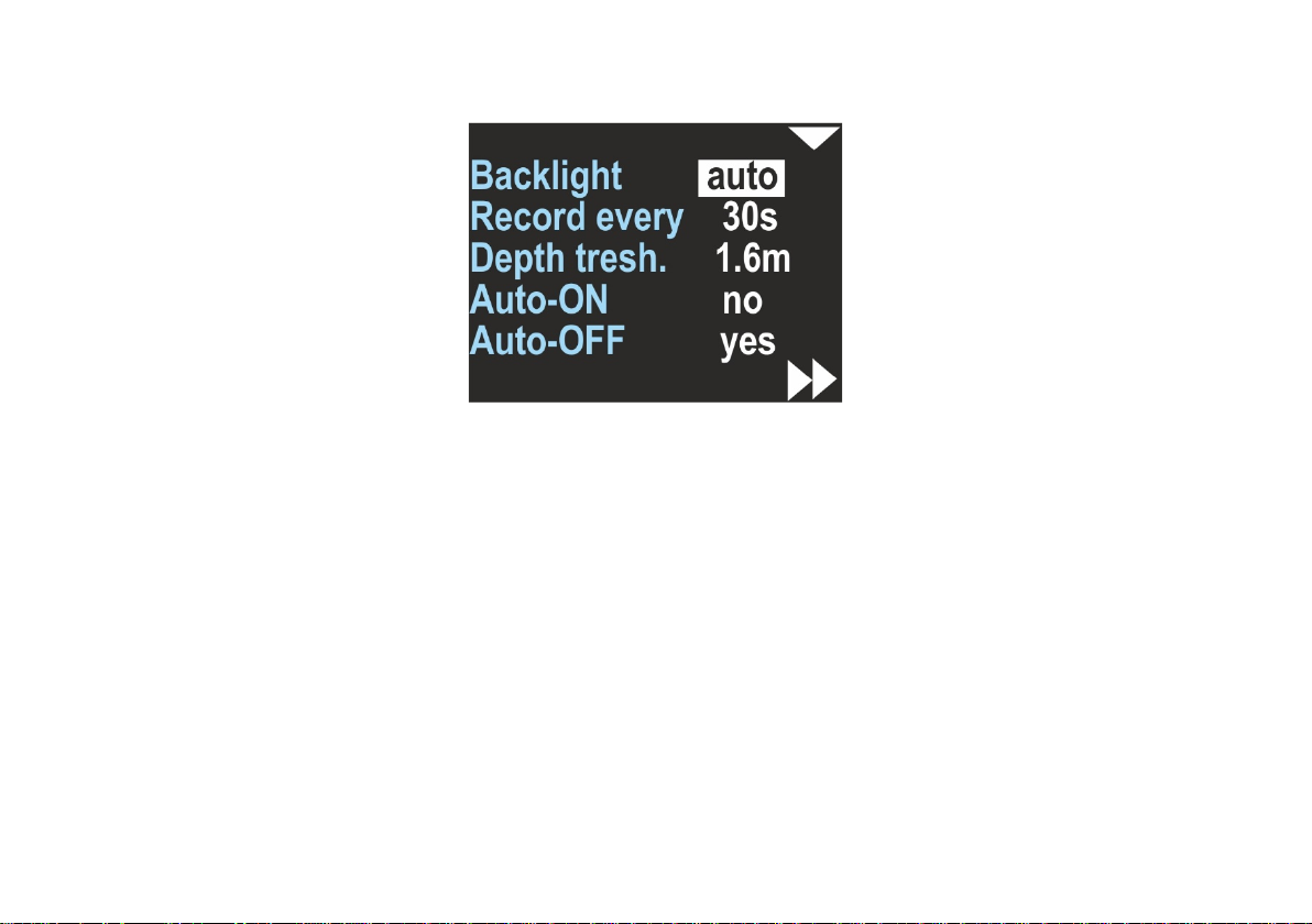
Miscellaneous other settings are available as a separate screen:
Backlight – [1,2,3,4,5,auto] – Changes the display backlight intensity. Value 1 means the constant lowest brightness
(about 20%), value 5 means the constant maximum brightness, value ‘auto’ means that the backlight will be auto
adjusted using the ambient light sensor.
Record every [2s,5s,10s,30s] – This is the maximum available time space between two records in memory. Note, that in
some cases two records may be collected faster than this value, but never longer.
Depth threshold [0.5m, 1m, 1.6m] – The navigation console will count ‘underwater time’, when the depth is equal or
greater than this value.
Auto-ON [y e s / n o] – If yes, device will switch on automatically when immersed in water by at least 0.3 meters ( 1 f t . ) .
Auto-OFF [yes/no] – If yes, the device will automatically power-off, if the water depth is at least 0.5 meters, RECORDING
is OFF (HOLD state), and the user did not press any button during the last 5 minutes.
38
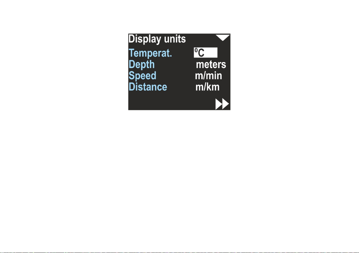
20. Units
Allows you to choose the units of the values presented on the screen:
Temperat.(ure) – Can be °C (Celsius) or °F (Fahrenheit)
Depth – Can be meters or feet
Speed – Can be m/min (meters per minute) or knots (nautical miles per hour)
Distance – Can be m/km (meters and above 2000m kilometers) or US.NM (United States Nautical Mile; 1US.NM = 1852m)
The selected unit is usually displayed near the values on all other screens.
39
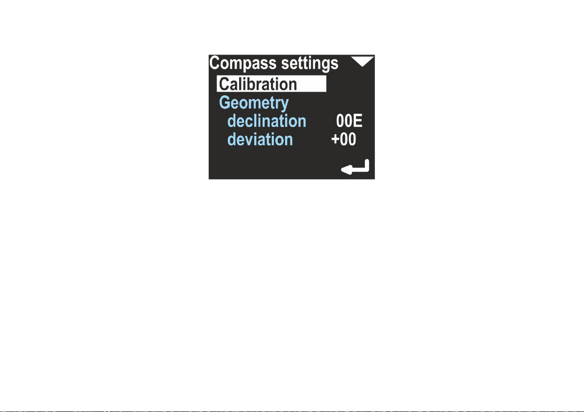
2 1. Compass
Allows to calibrate the magnetometer (compass sensor) and to set the magnetic declination and deviation.
Calibration – This option is used for basic magnetometer calibration. You should use this function, when the compass
direction shown on this device is improper. This is usually needed when the magnetic properties of the environment
have changed.
In every location, magnetic background, declination and other magnetometer-influencing factors are different. Thus,
the compass should be calibrated every time, when the location is changed, especially when there are big distances
travelled (travelling to another continent, or to a distant country).
Activate this function, and rotate the device slowly in all possible directions in 8-shape. This should take at least 1
minute. A green progress bar will be shown on the screen. The lower button will be marked as BACK until the progress
is less than 100% (time <1min). Pressing this button stops this operation, and no calibration data will be changed. After 1
minute, the lower button will be marked as SET, and pressing it will cause to apply the new collected calibration values
to the compass sensor.
40

Caution: The new calibration can be worse than the existing. If you are not happy with the results, calibrate the
compass again or restore the factory settings. After the basic calibration, you should set declination and deviation to 0
(zero), clear the precision calibration (see below), and set it again.
Geometry – This option allows a precision calibration. When activated, it will show you 8 coefficients. In an ideal case,
when no distortions are present, this coefficients should be: 0,45,90 ,135,18 0 ,225,270 and 315. This option allows to
achieve best compass accuracy (~1°). Without it, the compass accuracy can be 3-5° depending on the calibration quality
(described above).
Use the top button to change the option:
Exit – Return with no changes
Clear – Switch off the precision calibration and clear all its coefficients
Setup – Make a new precision calibration
To make a new precision calibration, you should use the SET option. You will be asked to set the device in true
geographical direction of 0, 45, 90, 135, 18 0 , 225, 270 and 315 degrees. The device should be positioned vertically, like
being attached to the DPV. The Display shows:
41

Current – Raw heading from magnetometer, without correction.
Stored – Stored value for this step.
The lower button will store the Current value as Stored, each time you press it. The upper button will guide you to the
next step. On the last screen you can check, if this calibration improved the heading display. This screen is named
‘Accuracy test’ and will show you:
Corrected – Heading value with applied correction
Measured – Raw heading value from magnetometer
Deviation – Calculated correction; Corrected = (Measured + Deviation) mod 360 .
42
If the corrected values are better than the measured values, press the lower button (ENTER) to store the results. If you
press the upper button, no changes will be stored.
Caution: Beware of placing another compass near this device when performing this calibration, because it might affect
the measurement and affects the calibration procedure.
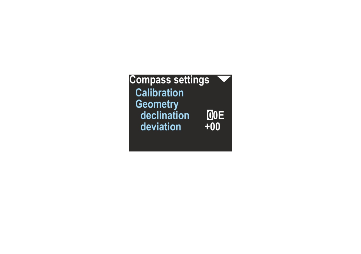
Declination - Set magnetic declination, a constant value that will be added to the heading shown on the display (and to
all position calculations). If the value is marked as E (East), the correction will be positive. When marked as W (West),
the correction will be negative. The magnetic declination is a constant value, depending on your geographical region. It
can be obtained from many sources.
Deviation – Set magnetic deviation, a constant value that will be added to the heading shown on the display (and to all
position calculations). The deviation is a constant value caused by magnetic elements near the navigation device, that
cannot be removed. In most cases it will be set to 0.
Note: The compass heading on the device display (and the data recorded in memory) will use both declination and
deviation coefficients. There is a common rule: declination is a matter of geographical location and deviation is caused
by other equipment. That is why these two coefficients are separated.
43

22. Clear data
Clears all records from the internal memory. The user will be asked, if he really wants to perform this operation.
It is recommended to power off and on the device after using this feature.
23. Factory reset
After using this option, all settings will be restored to factory values, and all other data will be lost.
You may want to use this option if:
- Swim records are invalid / incomplete or lost
- The device is not working correctly and you cannot find good settings
24. Exit
Exits the settings mode. The device returns to the main navigation screen.
44

25. Guidelines for attaching the ENC to DPVs
When using the navigation console with any DPV, you should carefully choose the mounting point for the device. An
unfavorable placement may cause magnetic interferences from your vehicle elements (battery, engine) to the ENC
compass sensor.
For a SEACRAFT® underwater vehicle, the recommended placement for the navigation device and its speed sensor is
shown below:
45

LIMITATIONS:
- ENC device should be placed at least 0,2m (7,9”) from any element containing ferromagnetic material (engine,
battery), permanent magnets (engine, vehicle handles, speed sensor) or electrical wires connecting the battery
with the motor. If this rule is violated, compass indications may be incorrect.
- Compass indications may be less stable when ENC tilt exceeds 35° (from vertical position). If you include your
vehicle lean, you should not exceed 35° inclination of ENC device vs vehicle body (see picture above).
- Log sensor should be placed away from any elements that can disrupt the flow of water. Front of vehicle is
almost always the best choice. Have in mind propeller “sucking” effect, and avoid placing it in the water intake
area.
If you need to place ENC device on some other kind of underwater vehicle, you have to find best mounting points on
your own, using picture above as guidance.
In order to maintain the correct compass accuracy, it is recommended to always calibrate the compass before diving.
Indicated by the compass the direction is calculated from the device measured by the magnetic components of the
Earth measured by the magnetometers. These components change depending on the location, local geological
conditions (eg the presence of ferromagnetic minerals) and are subject to periodic changes. Large ferromagnetic
elements, eg shipwreck, reinforced concrete port quay or steel elements buried in the bottom, also very strongly affect
the work of the compass.
A poorly calibrated compass or its disturbed operation can cause significant errors. In the case of a route with a length
of 1km, 5 degrees of compass error will result in an error in the calculation of the target of almost 88m.
One should also remember about the differences between the magnetic direction indicated by the magnetic compass
and the geographical direction that can be read from the maps. The difference between these courses is called
magnetic declination and depends on the location. The device allows you to set the magnetic declination and offset
this difference.
In order to optimally use the device, it is recommended to familiarize with the theory and principles of navigation in
detail.
The log sensor is a precise electromechanical device and must be protected against mechanical impacts and
contamination. After the dive, it is recommended to gently rinse with fresh water to cleanse any remaining vegetation
or mineral impurities. If it is necessary to make measurements with full precision, it is recommended to calibrate the
log every time.
46

26. Troubleshooting
Start charging battery for at least 30
Broken device (flooded, charged
Connect the charger for 1 minute. If
When switched on, the device shows
Broken battery.
Return the device for service.
Damaged charging cable or dirt/rust
Clean the charger connector. Make
Try another charger. You may use
Go to Settings / Pressure/salin. If the
Symptom Cause Solution
Device cannot be switched on.
Display is blank and no other
reactions is observed.
Device is switching on and off
continuously.
“Battery is low!” message and
switches off.
The charging process never ends.
The depth indication is 0 and never
changes.
Depth shown is invalid.
Excessive battery discharge.
from improper source), does not
react when charging
One of the internal sensors may be
damaged.
The battery is discharged too much. Charge the device.
on its connector.
Charging source too weak.
Defective pressure sensor.
minutes before attempt to switch on
the device. After few minutes, the
red led the will start blinking.
Factory service needed.
this will not help, allow the device to
discharge its battery and to switch
off. Wa i t 1 h o u r , and try to charge it
again. If this will not help, return the
device for service.
sure it is not cut or damaged.
the USB port of a laptop/PC.
pressure is near 0, the sensor is
defective and factory service is
needed.
47

The device is not switching on
automatically when immersed in
Wash the device using a mild stream
Disconnect the sensor plug , wash
The device is switched do INERTIAL
Go to Settings / Log/Speed, and
Perform the calibration as described
Try to remove the magnetic and
Defective sensor
Return the device for service.
water.
Pressure sensor gap filled with dirt or
mud.
of warm fresh water, until the
problem is gone.
External sensor is connected, but no
speed is shown.
Compass is showing improper
heading.
Note
Recommended intervals to re-check the required accuracy of the product - 36 months from the
date of purchase and the next every 24 months.
Sensor connector misfit, broken or
rusted.
operation.
Calibration required.
Strong external magnetic field near
the device.
and/or clean the connector, connect
it again.
make sure EXT is set to ‘Active Log’.
i n c h a p t e r 13. 1 a n d 13 . 2
ferromagnetic elements from the
vicinity of the navigation device.
Move the navigation device to
another location.
48
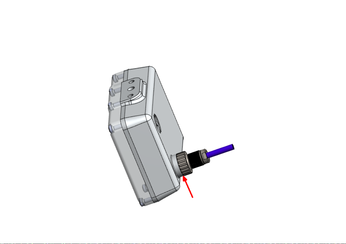
27. Before each dive …
Make sure that battery is charged enough. Power on device and check all important settings.
In order to connect the log to the device, check the state of the plug and socket, clean any impurities, check the o-
rings, apply a delicate layer of silicone grease and gently but firmly tighten.
Before diving you have to check, if output socket (in the back) is well tightened. Also you have to make sure, that none
of the sealing rings is broken or missing.
49
50

51

MARINE TECH SA
38-400 Krosno, ul. Żwirki i Wigury 17, POLAND
info@seacraft.eu
www.seacraft.eu
52
 Loading...