

Marine PC MPC-ML10DVR User Manual
MPC-ML10DVR
Digital Video Recorder
LCD Monitor
User Manual
www.MarinePC.com
N
S
E
W
MARINE PC
MARINE PC

2 MPC-ML10DVR-UM(B) 4/2011
Information Disclaimer
This MarinePC User Manual is provided “as-is”, without warranty of any kind, either expressed or implied, including but not limited to the implied warranties or merchantability and fitness for a particular purpose.
Documentation Change Notice
The information in this User Manual is subject to change without prior notice in order to improve readability and
reliability as well as design and function. These changes shall be incorporated in a new revision, available from
the product and/or download section of the MarinePC web site, www.marinepc.com.
Liability
In no event shall MarinePC be liable for direct, indirect, special incidental or consequential damages arising out
of the use of or the inability to use MarinePC’s product or its documentation, even if advised of the possibility of
such damages.
Endorsement
Product names mentioned herein are used for identification purposes only and may be trademarks and/or registered trademarks of their respective companies.
Copyright
This document contains proprietary information protected by copyright. All rights are reserved. No part of this
manual, in whole or part, may be reproduced by any means, in any form, without prior written permission of
MarinePC.
www.marinepc.com
Owner Record
Here is an easy-to-locate form to record the unit’s serial number, and from the invoice,
record the invoice date. The unit’s serial number is located on the back panel.
If the unit ever requires service, please refer to this information when contacting the
MarinePC Service Center.
Product Serial Number Invoice Date
MPC-ML10DVR ____
/ ____ / ____

MPC-ML10DVR-UM(B) 4/2011 3
MPC-ML10DVR
Military Grade
Digital Video Recorder
LCD Monitor
User Manual
www.MarinePC.com

4 MPC-ML10DVR-UM(B) 4/2011
Table of Contents
Introduction ......................................................... 5
Quick Start Guide ..................................................6
NVIS Option .........................................................9
Safety ............................................................... 10
Product Care and Maintenance ............................... 12
System Set-up .................................................... 13
Installation ........................................................ 14
Display Connections ............................................. 16
Operator Controls ................................................ 17
On-Screen Display ............................................... 18
Digital Video Recorder .......................................... 24
Video Gallery ..................................................... 26
Appendix A - Overview Drawings ............................. 27
Appendix B - Troubleshooting ................................. 27
Appendix C - Technical Specications ....................... 29
MPC-ML10DVR-UM(B) 4/2011 5
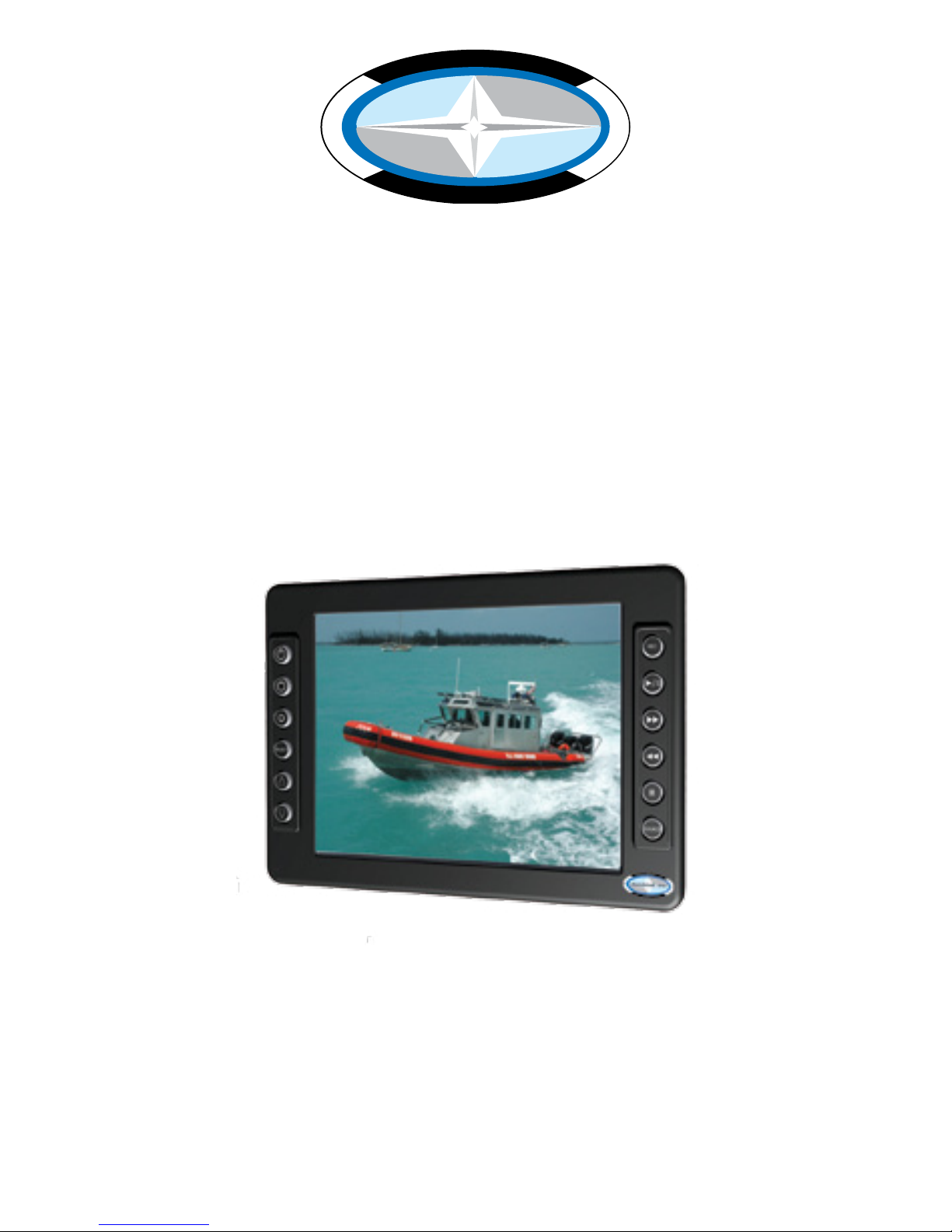
With the acquisition of an All-Weather Digital Video Recorder/Monitor, MPC-ML10DVR,
we welcome you to MarinePC’s family of ruggedized professional marine grade products.
You will soon become familiar with the quality difference in this bright sunlight-reada-
ble (~1 nit to 1,000 nits) Monitor, specically designed to meet or exceed MIL-Specs for
use in harsh marine environments. MarinePC has incorporated the latest LED backlighting to increase brightness and super-low dimming without increased heat, and extends
temperature, shock and vibration specications.
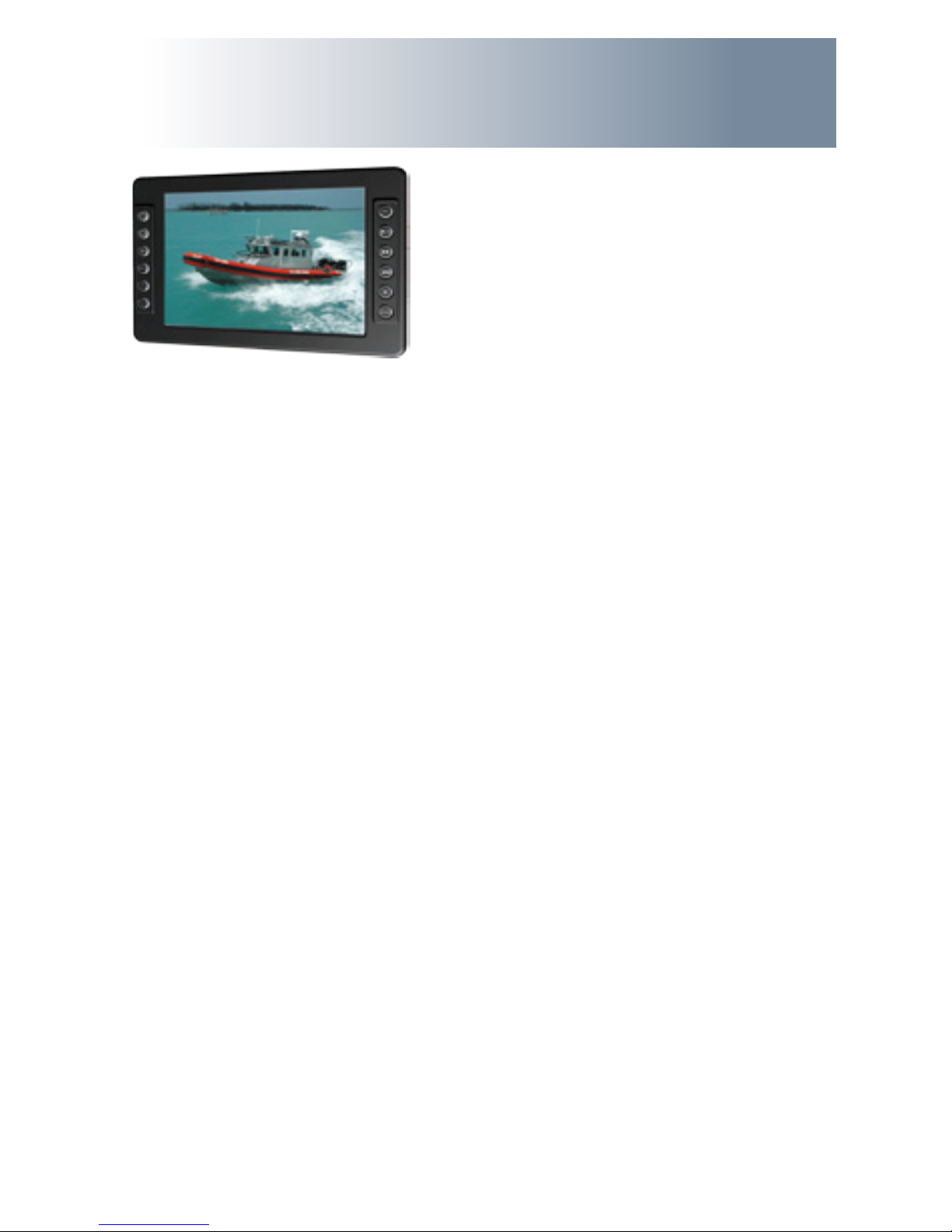
The MPC-ML10DVR also integrates full DVR capability directly inside the case of the waterproof monitor, eliminating separate mounting interconnecting cables, saving space
and providing environmental protection and tranportability for the DVR.
The MPC-ML10DVR handles a wide-range of severe environments, making it the rst
choice of serious mariners for their demanding applications. Designed to be rugged,
the 800x600 (SVGA) Resolution Flat Panel Display is engineered to mate perfectly to all
leading edge cameras including infrared, image amplied and visible spectrum sources.
Housed in a milled billet aluminum case, the slim-prole MPC-ML10DVR is light weight
and watertight, with fully sealed (IP67) case and standard MIL-C-38999 connectors.
Engineered to be energy efcient to conserve power, the MPC-ML10DVR has three
Composite Video inputs, with a source select button that lets you easily move between
up to three inputs, and also provides one video output. Recorded les can be easily
downloaded in standard .wmv le format via a USB connection.
Our MarinePC Service and Support Team is prepared to assist you – we are MarinePC.
Welcome.
6 MPC-ML10DVR-UM(B) 4/2011
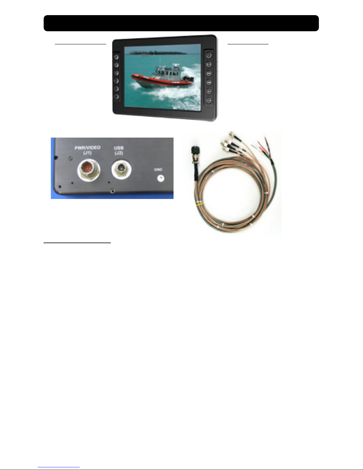
MONITOR OPERATION
Terminate Positive cable lead to 10-36 VDC positive voltage source and Negative lead
to negative voltage source. Plug in cable (supplied by Marine PC or FBO) into J1 and
turn CW to lock. (Connecting cable to J2 is only necessary for download.)
Connect at least one RS-170 device (camera, typically) to any of the three input
cables, marked 1, 2, 3, using standard BNC coax connector. Make sure the video
device is turned on and providing a signal to the MPC-ML10DVR.
Press Power On-Off Button once to turn on unit. After a few seconds of a power up
routine, the rst operational signal being received will be displayed. The LED backlight will automatically come on at about half brightness.
Adjust brightness by repatedly pressing the Brightness Up or Down button. Adjust to
the lowest setting which still allows ease of viewing. The last step of the Brightness
Down control is Backlight OFF. From this last step, pressing the Brightness Up button
one short time will put the backlight in the lowest possible setting of ~ 1 nit.
NOTE: Using the lowest brightness setting (backlight off) maintains power to the
other internal electronics and keeps them fully functional, including DVR recording,
while saving power and night vision. Pressing the brightness button will then allow
the backlight to come on and immediately display the video input and any recording function in progress. Using the Power On-Off button will turn off all electronics,
including DVR recording and the video processor. Turning the unit back on this way
will initiate a several second delay while all electronics initializes.
Power On-Off
Brightness Up
Brightness Dn
OSD Select
Next
Previous
Record On-Off
Rewind
Fast Forward
Stop
Source Select
DVR FunctionsMonitor Functions
Play - Pause
QUICK START

MPC-ML10DVR-UM(B) 4/2011 7
Selecting Video Sources
If more than one video device is connected and operational, selection of the video
source to be displayed on the LCD is made by pressing the button located on the lower
right of the MPC-ML10DVR. If two sources are present, pressing this button will switch
from one source to the other. If three sources are present, pushing this button will
successively display one, then the next and the next and then back to the original
source. The numbering of the input channels indicates the sequence of the selection
process.
Recording Video
The integrated full function DVR in the MPC-ML10DVR will record whatever is being
displayed on the LCD. If there is no active input, the DVR will not function. To start
recording, simply press the top right button marked REC. You will notice a RECORDING
message will be displayed in the upper right margin of the LCD to indicate recording
is in progress (this will not appear in the recorded le). A .wmv le with a sequenced
lename will be initiated including time and date information, and will continue to
capture whatever information is being displayed. If sources are switched, the DVR
will continue to record through the switch. The length of the le is indeterminate. To
stop recording, simply press the REC button again and the le will be closed and saved,
and the RECORDING message will disappear from the display. Alternately, pressing the
Stop button, marked with a square, will also stop the recording. This process can be
repeated any number of times, each time creating a unique .wmv le. Any number
of les can be created. A total of 8 hours of les can be recorded. If the solid state
memory storing the les is already full, the DVR will start to overwrite the existing les
starting with the oldest le.
VIDEO PLAYBACK
After stopping a recording, or at any other time when recording is not taking place,
any video le can be played back in the MPC-ML10DVR. To review any saved le,
simply press the Play-Pause button, second down on the right. The currently displayed
video input on the LCD will be replaced by the gallery, a list of thumbnail images of
sequentially numbered les. The last le saved will have the highest number and
be highlighted when entering this list. To select any previously saved le, press the
PREVIOUS button on the lower left. Press once to move back in sequence one at a
time. Use the NEXT button above the Previous button to move forward. To play back
the highlighted le, press the Play-Pause Button once to open this le, and press again
to play le from the beginning. Press again to Pause, press again to resume play. (TIP:
To speed the process from Record to Playback, simply pressing the Play button dur-
ing a Recording will automatically stop and save the le and put up the thumbnail le
display with the just stopped le hightlighted.)
FAST FORWARD - REWIND
While the le is being played, the le can be fast searched by using the middle two
buttons on the right side. The le will then be advanced or played backward at
double of normal speed.
TIP: In order to facilitate quickly locating the images to be reviewed, it is highly
recommended not to just turn on the record function and let it go continuously.
Rather, it is very much more useful to record many smaller les rather than one or
two enormous les.
DELETE FILE
Any selected le can be permanently deleted in the unit to remove unwanted les.
This will recover storage space and time for more recording. In the Playback mode,
note the Select button on the left side has been repurposed and the display will
show a DELETE FILE message. Press the Delete File button once, and the Display will
ask you to conrm this action and require a response of YES or NO using the Previous
and Next buttons.
LIVE DISPLAY
To return the display to the live video input from the selected source, press the Stop
button, which now has the LIVE FEED message. The MPC-ML10DVR now is displaying
live video. Sources can be switched and new Recorded les can be created.
DOWNLOADING FILES
To download les, an auxilliary USB cable must be attached to the MPC-ML10DVR.
The cable can be attached to any PC for standard Windows le transfer of the
stored .avi les in the unit to the computer. Once the cable is connected, press
the Play button. The Fast Forward button on the right side now has the DOWN-
LOAD message shown on the display. Press this button and the unit will now be
recognized by the PC as a memory device, much like a USB stick. Files can now
be either copied or moved from the MPC-ML10DVR to a le folder in the PC. It is
recommended in most cases that the les be moved in order to free up storage for
the next use. The process of transferring the les may take some time depending
upon the number and size of the les being transferred. Once stored in the PC, any
commercially available video player capable of processing les created with MPEG-4
compression (Windows Media Player, for example) can open and play the les. After
the download process is complete, remove the USB cable from the PC and press the
Stop button to return to Live Feed.
(NOTE: le transfers can ONLY be made from the MPC-ML10DVR to a computer.
The storage in the MPC-ML10DVR is permanently write protected through the USB
connection so that no external les or unwanted data can be introduced into this
storage.)
8
MPC-ML10DVR-UM(B) 4/2011
Once YES is selected, the le will be PERMANENTLY and
IRREVOCABLY DELETED!!!!
Caution!
MPC-ML10DVR-UM(B) 4/2011 9
NVIS OPTION
Overview
The MPC-ML10DVR is often used as a display for low light and infrared cameras for operations at
night. Operator situational awareness can be further enhanced with the use of Night Vision Goggles or Monoculars, commonly referred to as NVG’s. These devices amplify available light within
a certain spectrum to allow visualization of objects that are otherwise undetectable. At normal
display light levels, if the operator would look at the display through the NVG’s, the brightness
may cause them to “bloom” or become over-driven and momentarily blind the operator. The
brightness of the MPC-ML10DVR can be turned down to the very lowest setting and allow for direct use with Generation 1 & 2 NVG’s. For high amplication common with GEN3 NVG’s, even this
very low light is too much. To prevent this over-driving, NVIS “Green” compatible backlighting option is available that will limit the light used to backlight the display to frequencies not amplied
by the NVG’s, thereby allowing both those using NVG’s and those viewing normally to look at the
display. Alternately, some situations require the use of red spectrum lighting to preserve natural
night vision. As an option, the MPC-ML10DVR can be congured with NVIS “Red”to allow for use
in this environment The NVIS Option makes either mode of operation available to the operator
through a single button action.
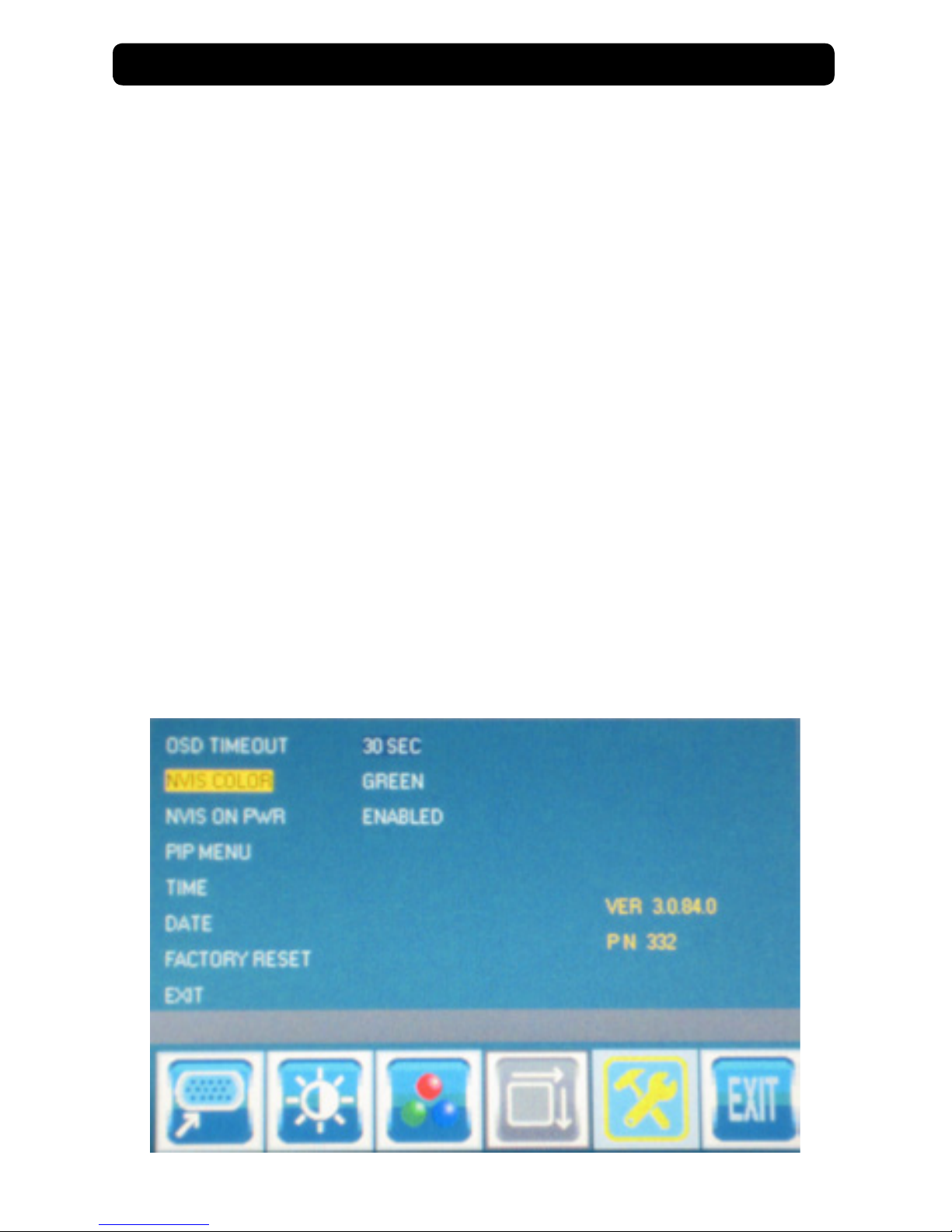
NVIS Green / Red OSD Setup
After pressing Select to enter the OSD, Select Tools, then select either NVIS Green or NVIS Red.
Once saved in the OSD, the UP / DOWN AROW Buttons will allow the operator to toggle between
that selection (Green or Red) and Day Mode. (NOTE: both NVIS colors are not available at the
same time.)
The Display will now automatically power on in NVIS mode. Daylight mode can be displayed by
pushing the UP ARROW Button. To return to NVIS Mode., push the DOWN ARROW button.
To Deselect the NVIS Option, reenter the OSD Select NVIS anddisable NVIS ON PWR.
10 MPC-ML10DVR-UM(B) 4/2011
SAFETY
General Safety Instructions
• Before operating the MPC-ML10DVR Monitor, read this User Manual thoroughly
• Retain this User Manual for future use
• Verify the computer system capability (see System Set-up) to insure operation of the
Monitor
• For expeditious installation, follow these User Manual instructions in the sequence
presented
• Adhere to all Caution and Warnings on system parts and as stated in this User manual
• All User Manual instructions for installation and operation must be followed precisely
• Adjust only those controls covered by the User Manual’s operating instructions; im-
General Unit Safety
• Always disconnect the unit from the power source before cleaning
• Do not operate the unit with a damaged cord
• Do not operate if the unit has been dropped or damaged. The unit needs inspected by
qualied MarinePC Service Personnel
• Position the power cord so it shall not be in contact with hot surfaces
• Do not allow anything to rest on the power cord, and
• Do not place the power cord where there shall be foot trafc.
General Safety Precautions
• Power cord must be connected to a properly wired and grounded power source
• Any equipment to which the unit shall be attached must also be connected to properly
wired and grounded power sources
• Do not connect or disconnect the unit during an electrical storm
• Do not remove the unit covers – there are no user serviceable parts in the unit
• Do not disassemble or modify the unit to avoid the possibility of electrical shock,
damage to electrical components or scratching the Display surface, and
• Disassembly of the unit voids the warranty.
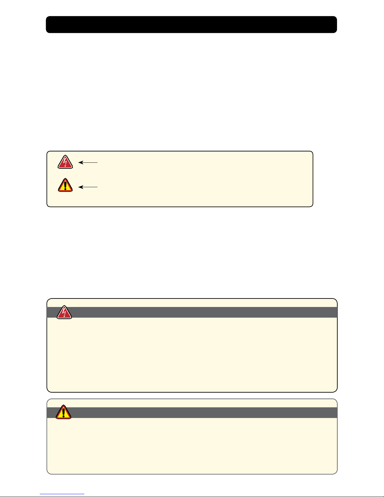
WARNING!
CAUTION!
Warning! Shock Hazards
This icon is intended to tell you of a potential risk of electrical shock.
Caution! Instructional
This icon is intended to tell you of important operating and/or
maintenance instructions.
Safety Icons
WARNING!
Fluids from LCD Display
• If the Monitor should ever become shattered, do not touch uids from an LCD Display
• If uid should get on hands or clothing, immediately wipe off with liquid soap or rubbing
alcohol; wash with water; consult with a doctor, and
• If uid gets in the eyes, ush eyes immediately with water for a minimum of 15 minutes;
consult with a doctor.
CAUTION!
 Loading...