

Marine PC MPC-MI19 User Manual
N
W
MARINE PC
MARINE PC
E
S
USER MANUAL
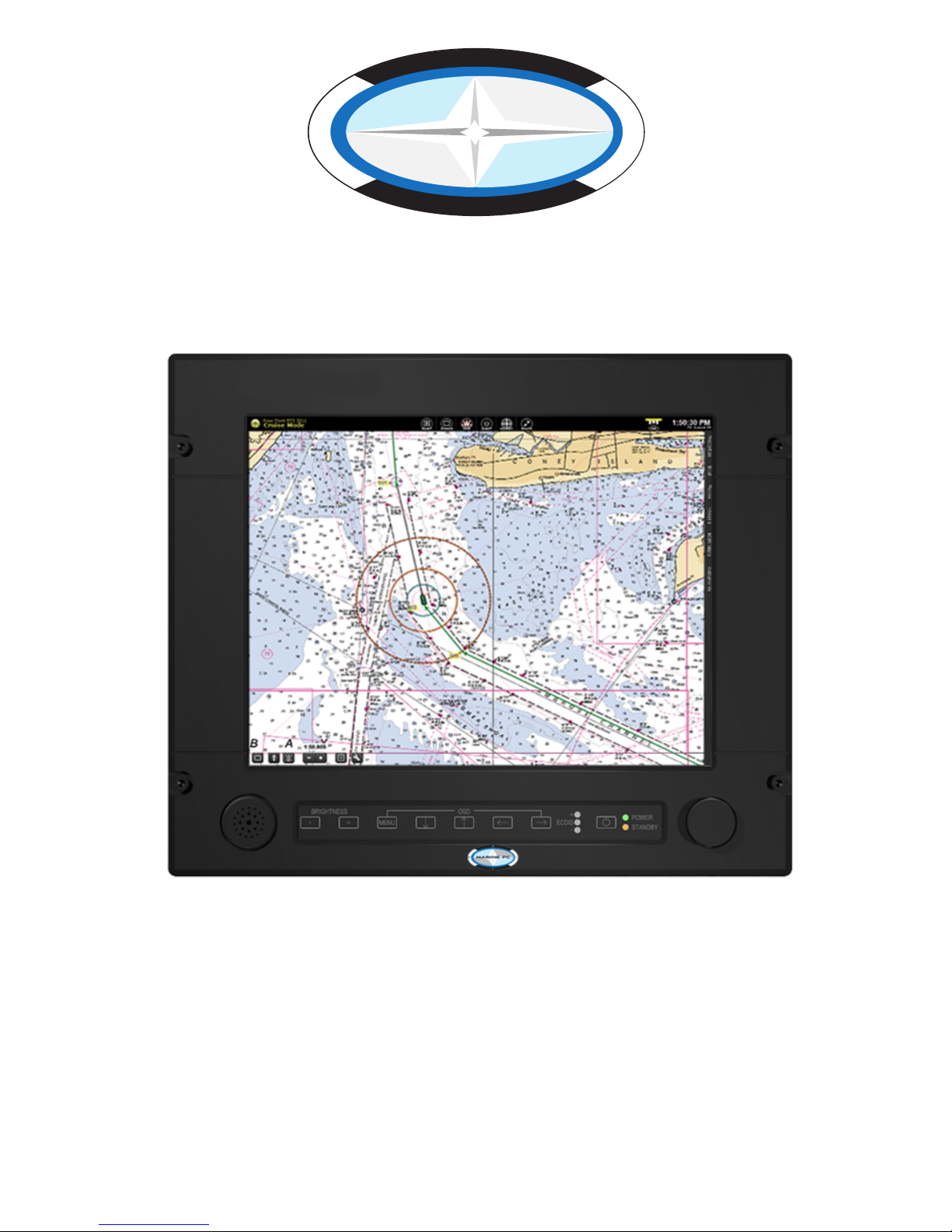
19” Bridge Display
Type Approved by ABS

Owner Record
Here is an easy-to-locate form to record the unit’s serial number, and from the invoice, record the
invoice date. The unit’s serial number is located on the back panel.
If the unit ever requires service, please refer to this information when contacting the MarinePC
Service Center.
Product Serial Number Invoice Date
MPC-MI19 ____
/ ____ / ____
CAGE CODE 3W7C2
GSA Contract GS-07F-0154T
1-480-515-1838
Information Disclaimer
This MarinePC User Manual is provided “as-is”, without warranty of any kind, either expressed or implied, including but not
limited to the implied warranties or merchantability and tness for a particular purpose.
Documentation Change Notice
The information in this User Manual is subject to change without prior notice in order to improve readability and reliability
as well as design and function. These changes shall be incorporated in a new revision, available from the product and/or
download section of the MarinePC web site, www.marinepc.com.
Liability
In no event shall MarinePC be liable for direct, indirect, special incidental or consequential damages arising out of the use of
or the inability to use MarinePC’s product or its documentation, even if advised of the possibility of such damages.
Endorsement
Product names mentioned herein are used for identication purposes only and may be trademarks and/or registered trademarks of their respective companies.
Copyright
This document contains proprietary information protected by copyright. All rights are reserved. No part of this manual, in
whole or part, may be reproduced by any means, in any form, without prior written permission of MarinePC.
WARNING
TO PREVENT FIRE OR SHOCK HAZARDS, DO NOT EXPOSE THIS UNIT TO RAIN OR MOISTURE.
RISK OF ELECTRIC SHOCK. DO NOT OPEN.
CAUTION: TO REDUCE THE RISK OF ELECTRIC SHOCK, DO NOT REMOVE COVER OR BACK, NO
This symbol warns the user that un-insulated voltage within
This symbol alerts the user that important literature
been included. Read it carefully to avoid any problems.
!
!
!
ALSO DO NOT USE THIS UNIT’S POLARIZED PLUG WITH AN EXTENSION CORD RECEPTACLE OR
OTHER OUTLETS UNLESS THE PRONGS CAN BE FULLY INSERTED.
DO NOT OPEN THE CABINET. THERE ARE HIGH VOLTAGE COMPONENTS INSIDE. REFER
SERVICING TO QUALIFIED SERVICE PERSONNEL.
CAUTION
USER-SERVICEABLE PARTS INSIDE. REFER SERVICING TO QUALIFIED SERVICE PERSONNEL.
the unit may be large enough to cause electric shock.
Therefore, it is dangerous to touch any part inside the unit.
about the operation and maintenance of this unit has
3

TABLE OF CONTENTS
CONTENTS ..............................................................................................................6
SHIPPING CARTON CONTENTS...................................................................................6
INTRODUCTION.......................................................................................................7
About MarinePC..............................................................................................................7
MarinePC
Customer Service.........................................................................................7
PRODUCT SAFETY PRECAUTIONS..............................................................................8
ABBREVIATIONS ...........................................................................................................9
MPC-MI19 USER FEATURES.....................................................................................10
INSTALLATION......................................................................................................11
General Installation and Mounting Instructions.........................................................11
General Installation and Mounting..............................................................................................11
Mounting Instructions .................................................................................................................11
Cables...........................................................................................................................12
DC power input connector assembly..........................................................................................12
Cable Connections.......................................................................................................13
AC Power Input ..........................................................................................................................13
DC Power Male Connector (24V DC IN) ....................................................................................13
RGB HD15 Female Signal Connector (RGB IN)........................................................................14
COMPOSITE BNC Connector (COMP 1) ..................................................................................14
COMPOSITE BNC Connector (COMP 2) ..................................................................................14
DVI-D VIDEO Signal Female Connector (DVI-D IN).................................................................. 14
SCOM (RS232) and Buzzer control input Female Connector (SCOM/BUZZER)......................14
Remote Brightness Interface Male Connector (REMOTE BRIGHTNESS)................................15
Programming / Field Service Interface (PROG).........................................................................15
Earth Ground..............................................................................................................................15
CABLE TIEDOWNS ......................................................................................................15
Compass Safe Distance...............................................................................................16
ECDIS Installation Setup .............................................................................................16
OPERATION...........................................................................................................17
FRONT PANEL DISPLAY USER CONTROLS..............................................................17
Power ON/OFF...........................................................................................................................17
OSD CONTROL BUTTONS.......................................................................................................17
OSD HOT KEYS.........................................................................................................................18
FRONT PANEL Backlight Dimming Control...............................................................................18
FRONT PANEL INDICATORS ...................................................................................................18
FRONT PANEL ALARMS ..........................................................................................................19
Buzzer – Remotely controlled.....................................................................................19
Remote Backlight Dimming Control...........................................................................19
OSD FUNCTIONS .........................................................................................................20
ECDIS OPERATION......................................................................................................24
Setting Controls for route monitoring..........................................................................................24
Color Differentiation Test Diagram Test.....................................................................................24
Grayscale Test ...........................................................................................................................25
Setting Backlight Brightness for ECDIS Operation ....................................................................25
Backlight Dimming
Operation.....................................................................................27
Front Panel LED Indicator Dimming Operation..........................................................27
MAINTENANCE......................................................................................................28
PREVENTIVE MAINTENANCE.....................................................................................28
Surface Cleaning........................................................................................................................28
CORRECTIVE MAINTENANCE ....................................................................................28
SPECIFICATIONS..................................................................................................29
4

APPENDIX ............................................................................................................. 32
SHIPPED OSD CONFIGURATION ................................................................................32
Function description for de-interlacing mode AFM, TNR, MADI, LADI .....................33
PIP mix table .................................................................................................................33
INPUT CONNECTOR PIN ASSIGNMENTS ........................................................... 34
DC Power Connection Male (24V DC IN) .....................................................................34
RGB HD15 Signal Connections (RGB IN) ...................................................................34
COMPOSITE BNC Connections (COMP 1) ..................................................................35
COMPOSITE BNC Connections (COMP 2) ..................................................................35
DVI-D VIDEO Signal Connections (DVI-D IN) ..............................................................35
SCOM (R
S232) and Buzzer control input Connections (SCOM/BUZZER) ................36
Remote Brightness Interface Connections (REMOTE BRIGHTNESS) ......................36
Programming / Field Service Interface (PROG) ..........................................................36
TROUBLESHOOTING TIPS ..........................................................................................37
SERIAL COMMUNICATION INTERFACE (SCOM-RS232) ................................... 38
Message Format ...........................................................................................................38
Response Time .............................................................................................................39
Backlight Brightness Minimum Value Command (BRI) INPUT: ................................39
Backlight Brightness Maximum Value Command (BRM) INPUT: .............................39
Backlight Brightness Comman
d (BRT) INPUT: ..........................................................39
(BZZ) INPUT: .................................................................................................................40
Download ECDIS DVI-D Table from Display Command (DND) INPUT: .....................40
Download ECDIS VGA Table from Display Command (DNV) INPUT: .......................41
Read ECDIS Table Number of Pages Command (CMD) INPUT: ................................41
Elapsed Time Counter Command (ETC) INPUT: ........................................................42
Request Manufacturer ID (MAN) INPUT: .....................................................................42
Serial Number Command (SNB) INPUT: .....................................................................42
Display Firmware Version (SWI) INPUT: ................................................................
.....43
Temperature Sensor Command (TMP) INPUT: ...........................................................43
Request Type/Model Number (TYP) INPUT: ...............................................................44
OSD Control Command (MCC) INPUT: .......................................................................45
INPUT ERRORS AND RESPONSES.............................................................................75
ADDR (Byte 1) Error ................................................................................................................... 75
IHCHK (Byte 6) Error .................................................................................................................. 75
ATTN (Byte 0) Error .................................................................................................................... 75
CMD (Byte 2/3/4) Error ............................................................................................................... 75
LEN (Byte 5) Error ...................................................................................................................... 75
DATA (Byte 7) Error ................................................................................................................... 77
IDCHK (Byte 8) Error .................................................................................................................. 77
Hex, DEC, ASCII conversion table ..............................................................................78
DISPLAY DIMENSIONS............... .......................................................................... 84
5

CONTENTS
SHIPPING CARTON CONTENTS
Thank you for purchasing this MarinePC MPC-MI19 Display.
The carton contains the items listed below:
• 19 INCH MPC-MI19 Display
• Mounting Accessory Kit
• Product CD containing:
– User’s Guide
– Data Sheet
• ECDIS CD with Color Tables (Optional)
I/O cable kits are available separately.
Please check the carton and its content for damage that may have occurred during
shipment.
Report any damage to the shipping agent immediately and do not operate the
display if it appears to have been damaged.
original shipping carton and packaging materials to prevent shipping damage.
All warranty returns must use the
Report any damage to the shipping agent immediately and do not
operate the display if it appears to have been damaged. All
6

INTRODUCTION
With this purchase of this Marine Grade Bridge Display, the MPC-MI19, we welcome you to
MarinePC’s family of ruggedized marine grade products.
Serious mariners require serious products for their demanding applications. MarinePC has
been dedicated to providing exceptional computing and display products for the maritime
industry for many years. We are proud to be a chosen supplier of many Navies and Coast Guards
around the world, Commercial Maritime, military and para-military forces, state and
local law enforcement, as well as recreational users.
MarinePC is based in Phoenix, Arizona USA. This product is designed, manufactured and tested
in the United States, and is certied compliant with the IMO Standard IEC60945 for Maritime Bridge
Electronics by the American Bureau of Shipping (ABS).
MarinePC oers a full range of marinized LCD Displays and Computers, from our outdoor waterproof
8.4”, 10.4”, 12.1” and 15” MPC-AWM Professional Series (also available in MIL-STD version), to our
standard duty and ABS Type Approved Bridge Displays, Indoor and Outdoor Integrated PanelPC’s,
fanless ruggedized computers and our 19” rack mount fully congurable computers and servers.
All of our computer products are open architecture and use genuine Intel Core processors.
7

PRODUCT SAFETY PRECAUTIONS
Follow all warnings and instructions marked on the display.
Do not attempt to service this display yourself. Removing the display cover or back
may expose you to dangerous voltage or other risks. Refer all servicing to qualified
service personnel.
Adequate ventilation must be maintained to ensure reliable and continued operation
and to protect the display from overheating.
To protect from electrical shock, unplug the display from the power source before
relocating.
This display should be operated from the type of power source indicated on the
displays rating label.
Do not place any heavy objects on the power cord. Damage to the cord may cause
shock or fire.
Unplug this displays power source and refer servicing to qualified service personnel
in the event that:
Power cord or plug is damaged or frayed.
The display does not operate normally whe
followed.
The display has been dropped or the cabinet damaged.
The display exhibits a distinct change in performance, indicating a need for
service.
n the operating instructions are
8

ABBREVIATIONS
ACK – Acknowledge
AMLCD – Active Matrix Liquid Crystal Display
2 –
cd/m
DVI-D – Digital Video Interface
ENC – Electronic Navigational Charts
ESD – Electrostatic Discharge
ECDIS – Electronic Chart Display and Information Systems
Hz – Hertz
IAW – In Accordance With
IHO – International Hydrographic Organization
kHz – Kilohertz
LCD – Liquid Crystal Display
LED – Light Emitting Diode
NAK – Negative Acknowledge
NTE – Not To Exceed
OSD – On Screen Display
PBP – Picture By Picture
PIP – Picture In Picture
RX – Receive
RGB – Red, Green, Blue video
SCOM – Serial Communication interface
TX – Transmit
VAC – Volts, Alternating Current
VDC – Volts, Direct Current
VESA – Video Electronics Standards Association
VGA – Video Graphics Adaptor
Candelas per meter squared
9

MPC-MI19 DISPLAY FEATURES
Capable of displaying 16,772,166 colors: The display’s high-contrast LCD
enhances color vibrancy and improves focus with no geometric distortion.
Auto Screen size adjustment: Will adjust display for optional performance and
provide full screen images on even non-native formats.
Wide viewing angle: ±89° typical all directions.
Anti-Reflective Screen: All models are supplied with Anti-reflective Anti-glare
rotective safety glass.
p
Low power consumption.
10

INSTALLATION
General Installation and Mounting Instructions
General Installation and Mounting
• Our displays are designed for various installation mountings (panel mounting, bracket
mounting and VESA mounting). For details please see our installation drawings.
• When mounting the display in a confined area, i.e. console, adequate ventilation must
be provided to limit the maximum temperature to 55°C.
• The distance of each electronics unit from the magnetic standard compass or the
gnetic steering compass must not be less than the permitted safe compass distance
ma
of the device. See the safe compass distance later in this section.
• The maximum cable lengths must not exceed the recommended industry
recommended lengths.
• The display must be properly grounded. A short wide cable (braid) gives the best
results.
• For ECDIS applications, the calculated nominal recommended viewing distance is
1,013 mm. (IEC62288, Part 7.5 Screen resolution).
Mounting Instructions
The display can be mounted to a custom mounting bracket (not supplied), panel mounted
or VESA mounted. The following is a list the required mounting hardware (not supplied):
Panel mounting x4 - 6.2mm Dia. holes left and right sides
Panel mounting x4 – m6 inserts on rear top and bottom
VESA mounting x4 – m4 inserts on rear cover
Bracket mounting x8 – m6 inserts, 4 per side on rear cover
11

- +
Mating Side
Cables
Only high quality shielded signal cables should be used. Video cables should be kept as
short as possible to preserve the quality of the video signal. The maximum signal cable
length will depend on the signal type, resolution and frequency, in addition to the quality of
the signal output of the video source.
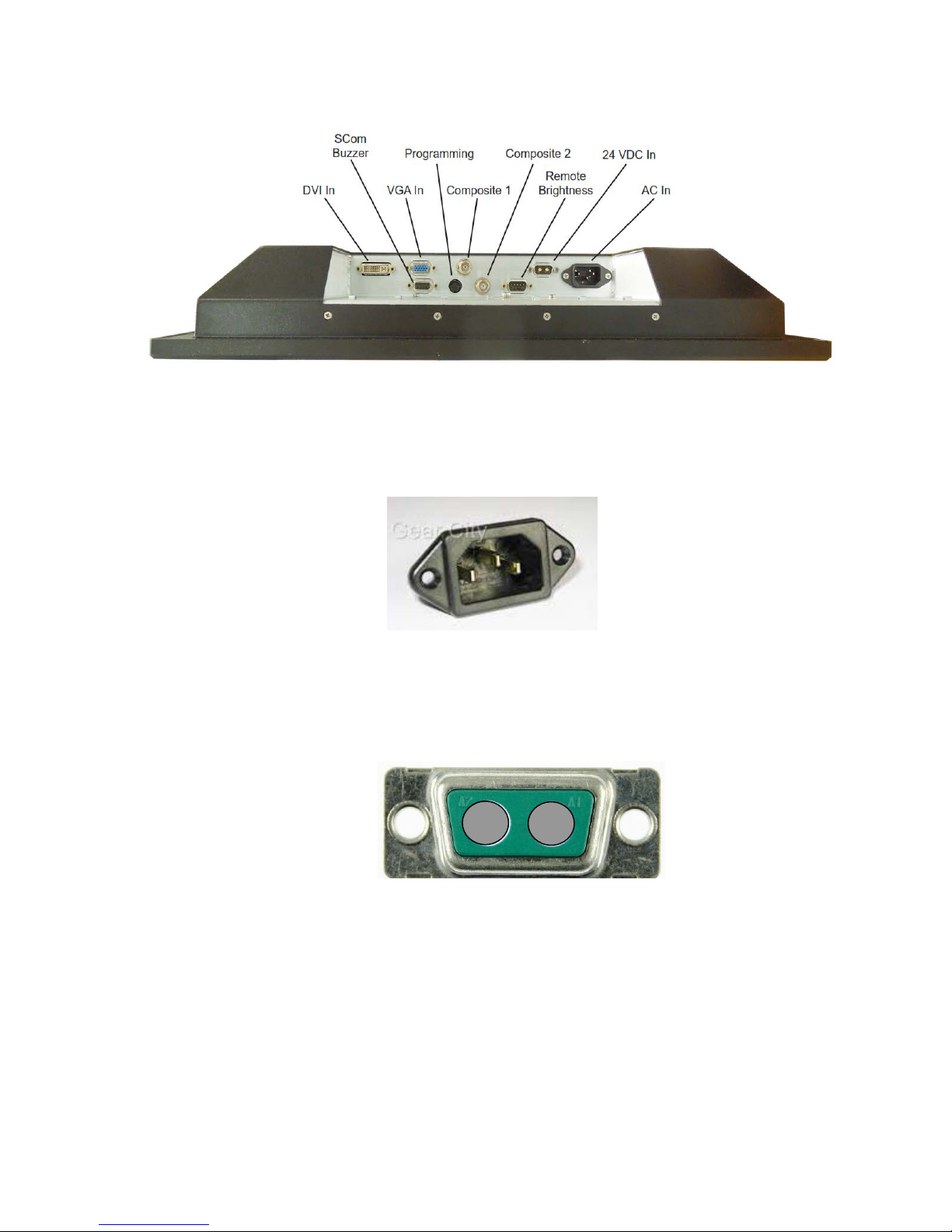
DC power input connector assembly
The mating two pin DC Power connector, two contacts and back shell are available
separately. For installation follow the followi
ng procedure.
1. Select the smallest compression insert that will fit over the DC power wires
2. Insert the wires through the compression insert.
NOTE: Wires must be properly sized to support the current related to the input
voltage being used and the length of the wires.
3. Solder the contacts to the +24 VDC wire and the 24 VDC return wire.
4. Insert the contacts into the connector housing noting the proper polarity.
5. Open the back shell by removing the two cover screws.
6. Assemble the connector and back shell as shown below
12
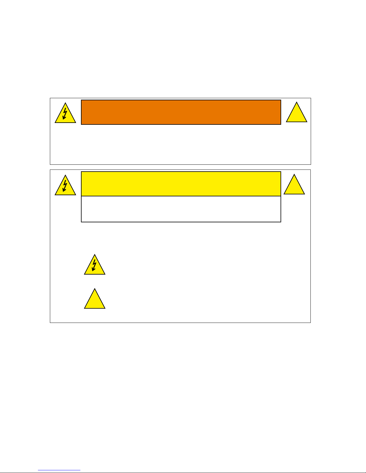
Cable Connections
+ -
Mating Side
AC Power Input
AC operating input voltage is 90-264 VAC Auto-ranging, 47-400 Hz, IEC-320 display
connector. Mating power cord is available separately.
DC Power Male Connector (24V DC IN)
Connect the DC Power input connector to the two pin male connector and secure
the cable with the two jack screws. The input voltage is 24 VDC nominal (9-32 VDC)
is supported. Mating DC power connection kit is available separately.
NOTE: The display will accept both AC and DC inputs at the same time. In this
configuration the AC power is the primary power. If AC power is lost or shut off, the
display will automatically switch over to the DC power input without affecting the
operation of the unit.
13
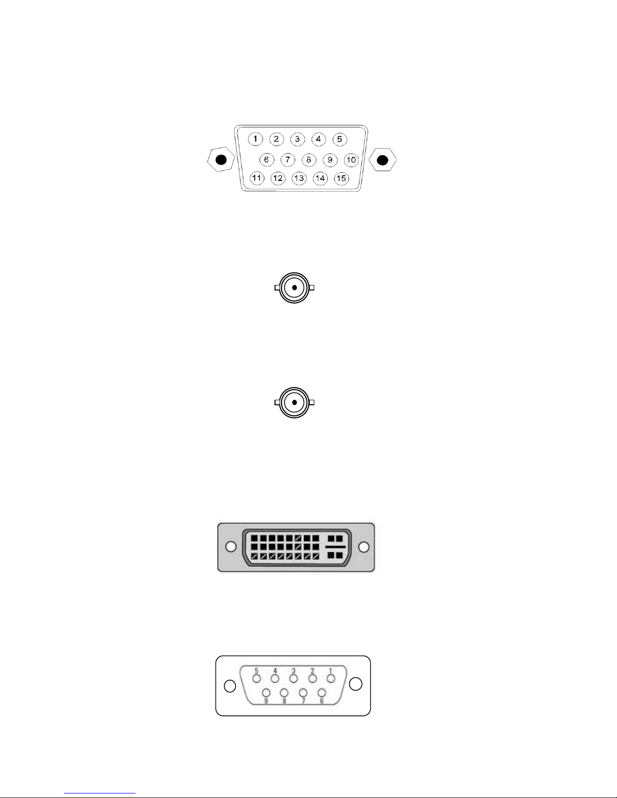
RGB HD15 Female Signal Connector (RGB IN)
The LCD Display RGB input can be connected to a video source using a HD15male to HD15-male cable available separately.
COMPOSITE BNC Connector (COMP 1)
Connect the BNC cables (not provided) to the COMP 1 BNC connector on the back
of the display as shown below.
COMPOSITE BNC Connector (COMP 2)
Connect the BNC cables (not provided) to the COMP 2 BNC connector on the back
of the display as shown below.
DVI-D VIDEO Signal Female Connector (DVI-D IN)
The DVI-D input is Digital Video input only. The DVI-D input connector uses a DVI-I
female connector to accept both DVI-I and DVI-D video cables. The LCD should be
connected to a video source using the DVI-D-male/male cable available separately.
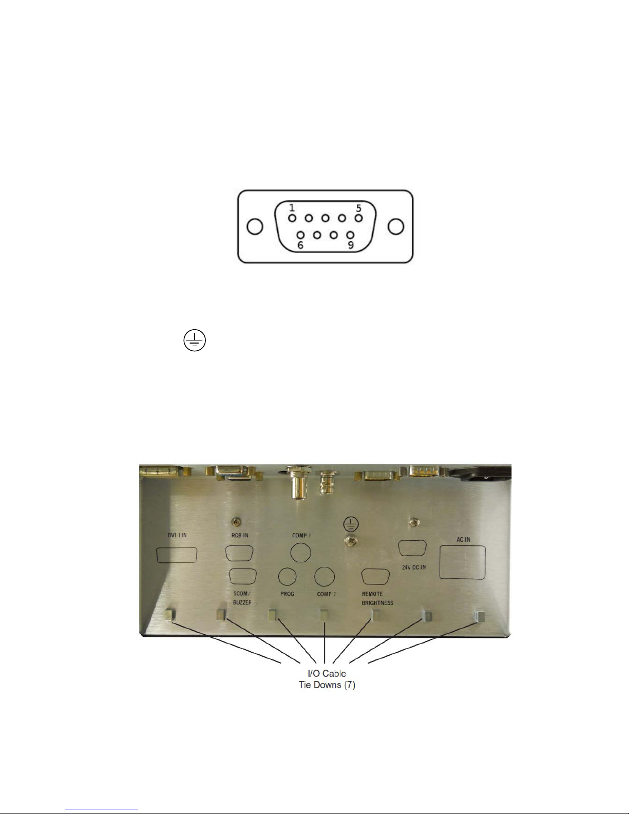
SCOM (RS232) and Buzzer control input Female Connector (SCOM/BUZZER)
Connect an RS232 Serial Cable (not provided) from the DB9 female input connector
on the back of the unit to the host computer RS232 Interface.
14
Remote Brightness Interface Male Connector (REMOTE BRIGHTNESS)
Connect the remote brightness Cable (not provided) to the DB9 male input
connector on the back of the unit. The brightness of the LCD Display can be
controlled remotely through this interface connector using two push button switches
for brightness up and brightness down. Also, the remote brightness potentiometer
(10K pot) can be connected through this interface connector.
Programming / Field Service Interface (PROG)
This interface is only for field service and manufacturing use.
Earth Ground
An M4 screw is provided for earth ground. It should be connected using a braid or
wire.
CABLE TIEDOWNS
After the I/O cables are attached to the input connector, secure them with a cable tie
(provided) to the appropriate tie-down.
15

Compass Safe Distance
The following is the compass safe distance for the MPC-MI19 19 inch display:
Front of unit: 200mm 0.3° deflection
Rear of unit: 300mm 0.3° deflection
Left side of unit: 0° deflection
Right side of unit: 0° deflection
ECDIS Installation Setup
For ECDIS applications, the calculated nominal recommended viewing distance is 1,013
mm. (IEC62288, Part 7.5 Screen resolution).
The VGA and DVI-D ECDIS tables are provided on a C
tables must be loaded onto the ECDIS computer for proper operation of the display.
After the display has been mounted and cabled up, it must be checked for proper ECDIS
operation see ECDIS Operation section on page 23.
D along with the display. These
16
MENU
OPERATION
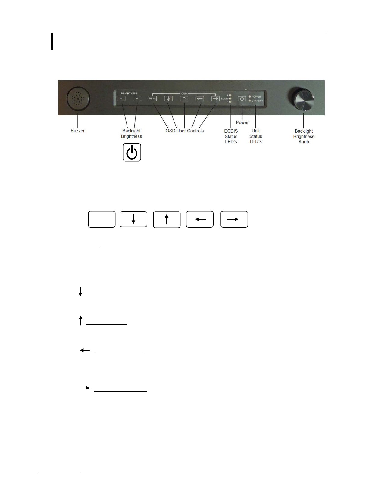
FRONT PANEL DISPLAY USER CONTROLS
The operator front panel user controls are described below.
Power ON/OFF
The POWER Button is used to power the display ON and OFF. Press and hold the
POWER Button for 3 to 5 seconds to power the unit ON or OFF. When power is first
applied to the display it will power ON automatically.
OSD CONTROL BUTTONS
MENU
Turns the OSD menu on
Return to previous OSD menu page
Exit the OSD menu (will also auto time out)
SELECT DOWN
Moves the selector to the next function (down)
SELECT UP
Moves the selector to the previous function (up)
SELECT LEFT
Moves the main selector to the left
Decrease the OSD parameter values
SELECT RIGHT
Moves the main selector to the left
Confirm to select the OSD function
Increase the OSD parameter values
17
-
BRIGHTNESS
+
Hot key 1 Hot key 2
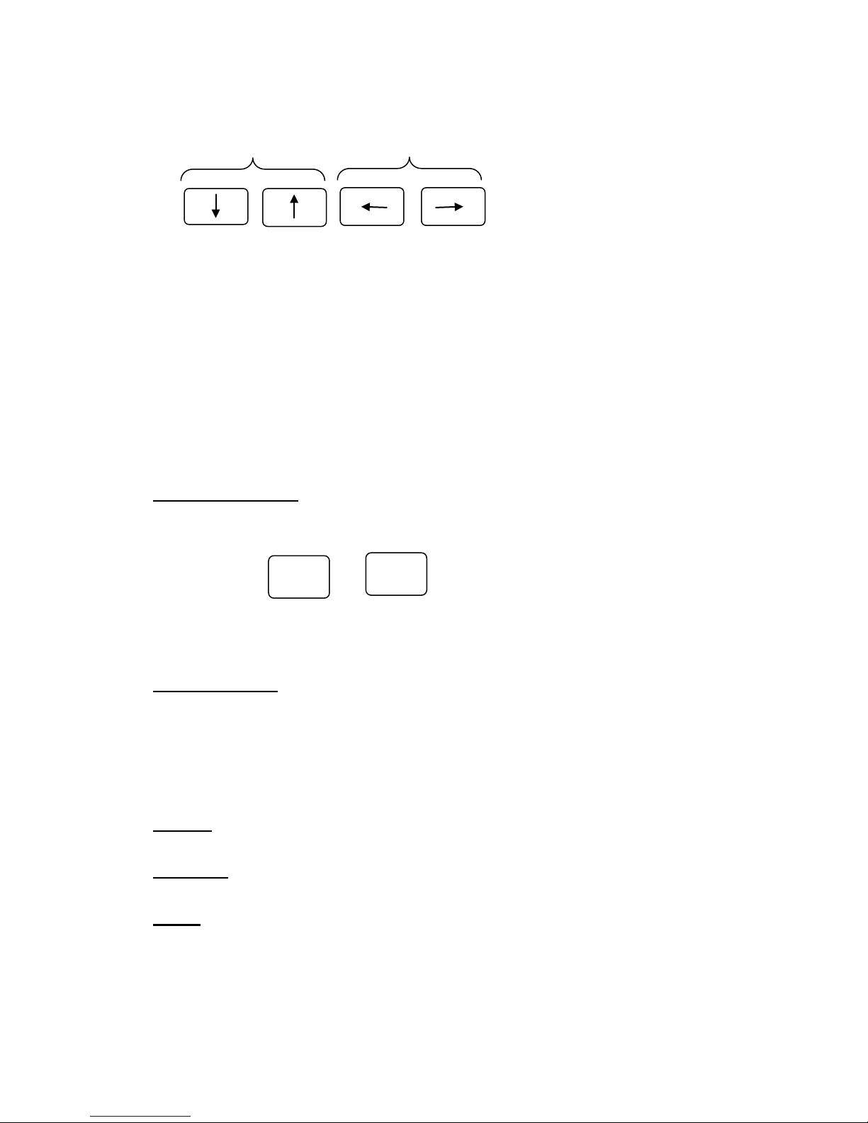
OSD HOT KEYS
The OSD Hot key adjustment is disabled.
Hot key 1 function is initiated by either the up arrow or down arrow. Hot key 2 function is
initiated by either the left arrow or right arrow. Pressing any of these keys will cause a
small screen to appear with an adjustment bar. Pressing the arrow keys again will cause
the level indicator to move but no adjustment will be made since the Hot key adjustment is
disabled. The adjustment
button.
box will time out or can be removed by pressing the MENU
FRONT PANEL Backlight Dimming Control
NOTE: Use of a Brightness control may inhibit visibility of ECDIS information,
particularly when using the night color tables
Backlight Buttons
The backlight brightness is increased and decreased by pushing the Plus and Minus
buttons respectively.
Backlight Knob
The backlight brightness is increased and decreased by turning the knob clockwise
and counter-clockwise respectively.
FRONT PANEL INDICATORS
POWER (Green) – Indicates that the display is powered ON.
STANDBY (Amber) – Indicates that there is no video input or format is out of range.
ECDIS
ECDIS (Green) – Calibrated for ECDIS when illuminated
ECDIS + (Red) – Brightness is above the calibrated value
ECDIS – (RED) – Brightness is below the calibrated value
18

FRONT PANEL ALARMS
-
+
Buzzer – Remotely controlled
The Buzzer can be activated through a remote switch or through the SCOM
(RS232) interface.
Remote Backlight Dimming Control
NOTE: Use of a Brightness control may inhibit visibility of ECDIS information,
particularly when using the night color tables
Remote Backlight Buttons
The backlight brightness is increased and decreased by pushing the remote Plus
and Minus buttons respectively.
Remote Backlight Potentiometer
The maximum backlight brightness is increased and decreased by turning the
Remote Backlight Potentiometer knob clockwise and counter-clockwise
respectively. This pot sets the maximum backlight brightness of the display. This
pot must be disconnected for ECDIS operation
19
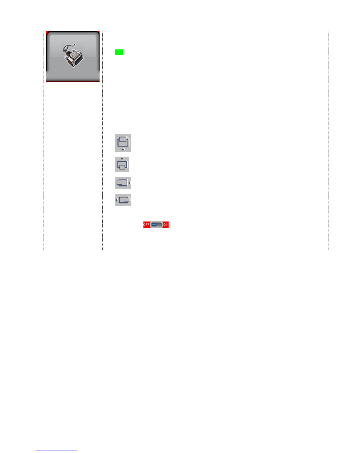
Picture :
## : DISPLAY IN VIDEO MODE ONLY
Move the image position upward
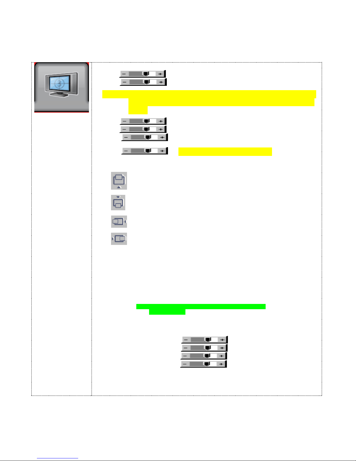
OSD FUNCTIONS
The OSD settings highlighted in green are the preferred settings. See the shipped OSD
configuration in the APPENDIX.
Brightness Increase/decrease panel brightness level, total: 100 steps
Contrast
Increase/decrease panel contrast level, total: 100 steps
NOTE: Use of the Brightness or Contrast controls may inhibit visibility
of ECDIS information, particularly when using the night color
Saturation
Hue **
Sharpness*
Backlight (OSD CONTROL DISABLED)
Position
Aspect / Size
- Fill Screen : Enable full screen expansion for lower resolution Image
- 4 : 3 : scaling format in 4:3
- 16 : 9 : scaling format in 16:9
-
- 2.35 : 1 : scaling format in 2.35:1
- 2 : 1 : scaling format in 2:1
- 1 : 1 : Display the exact image resolution on the screen without
image expansion.
- Custom Sizing
tables.
Increase/decrease saturation, total: 100 steps
Increase/decrease Hue level, total: 100 steps
Increase/decrease sharpness, total: 30 steps
#
Move the image position downward
Move the image position to the left
Move the image position to the right
- Fill to Aspect Ratio: Enable fill screen expansion for lower resolution
image according to aspect ratio
16 : 10 : scaling format in 16:10
##
- Overscan
- Normal
- Custom
H Size
V Size
H Pan
V Pan
:
** : FUNCTION IN ARGB/ DVI / VIDEO NTSC MODE ONLY
# : FUNCTION IN ARGB MODE ONLY
* : DISPLAY IN VIDEO MODE ONLY
20
Input :
Select the input video signal
Move the PIP position upward
Move the PIP position downward
Move the PIP position to the left
Move the PIP position to the right
MAIN Input Source:
VGA
DVI
Composite 1
Composite 2***
PIP Setup
PIP Source
VGA / DVI / Composite 1 / Composite 2 / Off
PIP Size : Off / Small / Medium / Large / PBP
4 possible input groups that can be mixed for PIP :
a) VGA
b) DVI
c) Composite 1 / Composite 2
Not allow to select signal source from the same group for PIP. [See Appendix – PIP mix table]
PIP Position :
PIP Swap : Swap between the main window and PIP window
PIP Auto off :
ON : When PIP has no signal input after 30 seconds, the PIP
window will turn off automatically.
OFF : PIP window stays on
: OFF / ON
*** DISPLAY WHEN SETTING ‘ON’ UNDER SETUP AUTO SOURCE SEEK
21
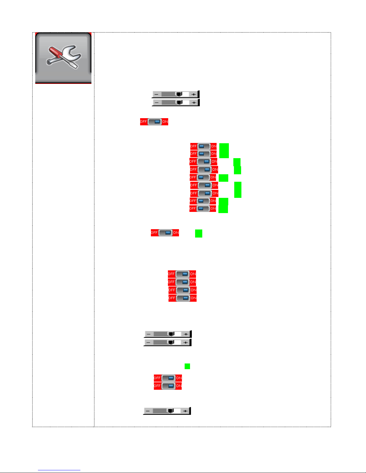
Utilities :
Use “-“ button to decrease the zoomed image
Setup
- Off
- 1280x768
- 1366x768
OSD
Zoom
Auto Picture Setup
Auto Color Gain
Wide Screen Mode detection
Manual Clock
Manual Phase
quality)
Auto Source Seek :
- Auto :
ON – Auto source select always enable
OFF – Disable auto source select function
- Setup Selection for the corresponding input sources detection
HD/SD SDI 1 : OFF / ON
HD/SD SDI 2 : OFF / ON
VGA : OFF / ON
DVI : OFF / ON
HD Component : OFF / ON
Composite 1 : OFF / ON
Composite 2 : OFF / ON
S-Video : OFF / ON
SD Component : OFF / ON
The corresponding input port name display on OSD menu will disappear once
setting “OFF”.
Auto Power : OFF / ON
ON – Enable soft power off function if absence of input signals
OFF – Disable soft power function
Video Standard (SD)* : Auto / NTSC / NTSC 4.43 / PAL / PAL M / SECAM
Image Orientation : Normal / Horizontal flip / Vertical flip / Rotate
Gamma : 1.0 / 1.6 / 1.7 / 1.8 / 1.9 / 2.0 / 2.1/ 2.2 / 2.3 / 2.4 / 2.5 / 2.6 / User Setting
De-interlacing Mode*
TNR
MADI
LADI
[See Appendix for AFM, TNR, MADI, LADI function description]
OSD position :
H POS
V POS
OSD Timeout (sec) : ON – 60 : Adjust the OSD menu timeout period in a step of 5
seconds (max 60 seconds)
ON =
60 = 60 seconds later will turn off the OSD menu.
Language : English / Chinese : Select OSD menu language display
Transparency :
Display Input :
Zoom level :
Use “+” button to zoom in the image
#
: Auto adjust the image position, phase and size
#
: Auto Color Calibration (See appendix)
#
: Adjust the image horizontal size
#
: Fine tune the data sampling position (adjust image
AFM
#
: Recognize the wide screen mode coming from ARGB port
: OFF / ON
: Auto Film Mode
: Temporal Noise Reduction
: Motion Adaptive De-interlacing
: Low Angled De-interlacing
: Move the OSD menu image horizontally
: Move the OSD menu image vertically
Continuous to display OSD menu.
: OFF / ON: Set OSD transparency
: OFF / ON: Display input port name when source switching
: Enable the zoom in function on the image displayed.
22
Horizontal pan : : Pan the image horizontally
# : DISPLAY IN ARGB MODE ONLY
Vertical pan :
Reset to Defaults : Restore to default values
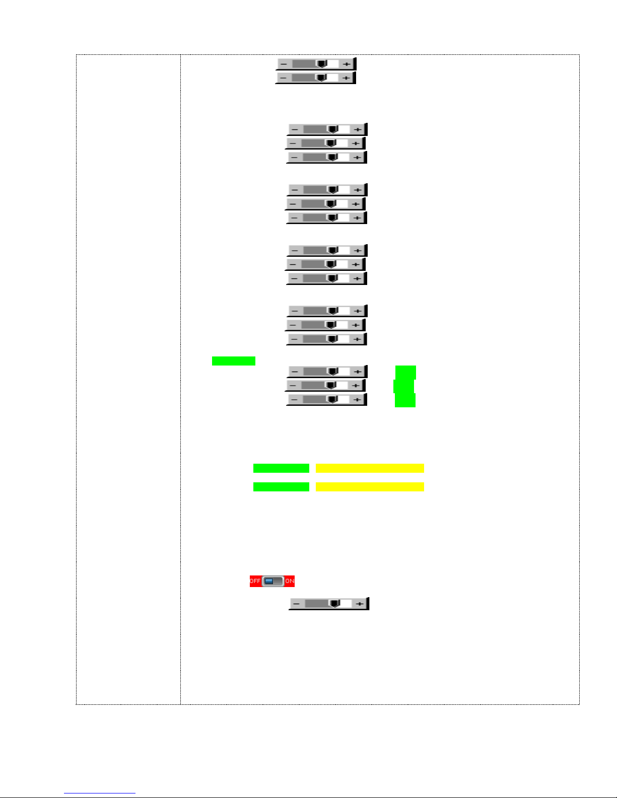
Color Temperature
Hot Key
Monochrome Mode
Backlight Setup
- B/L Invert :
- B/L Control : D/A / PWM : Selection for voltage level dimming control
- Backlight Frequency :
Default Setting
- Reset to Factory Defaults
- Reset to Factory Defaults with (Color Temp)
- Restore to Calibrated Defaults
5000K
R Gain :
G Gain :
B Gain :
Reset to Defaults : Resume to the default values
6500K
R Gain :
G Gain :
B Gain :
Reset to Defaults : Resume to the default values
8000K
R Gain :
G Gain :
B Gain :
Reset to Defaults : Resume to the default values
9300K
R Gain :
G Gain :
B Gain :
Reset to Defaults : Resume to the default values
User setting :
R Gain : Set to 100%
G Gain : Set to 100%
B Gain : Set to 100%
Reset to Defaults : Resume to the default values
Reset All to Defaults : Reset all color temperature settings to the default values.
Hot key 1 : Set to Backlight (OSD CONTROL DISABLED)
Hot key 2 : Set to Backlight (OSD CONTROL DISABLED)
- Color
- Red Monochrome
- Green Monochrome
- Blue Monochrome
: Invert for the backlight brightness
: Pan the image vertically
100 ~ 440Hz in a step of 20
* : DISPLAY IN VIDEO MODE ONLY
23

ECDIS OPERATION
The remote brightness pot must be disconnected for ECDIS operation.
This Display has been calibrated for ECDIS operation at the factory and is provided along
with an ECDIS Color Calibration CD containing the ECDIS information and color tables.
Setting Controls for route monitoring
It is important that the display be adapted to lighting conditions on the bridge by selecting
the correct color table (Day, Dusk or Night).
The controls should only be used for
In-addition to the external backlight brightness controls readily available to the mariner, the
LCD Display has internal controls, under the On Screen Display (OSD), available for
service engineers. These controls are the contrast and video brightness adjustments.
fine adjustment within the appropriate color table.
NOTE: Use of the Video Brightness and Contrast controls may inhibit
visibility of ECDIS information, particularly when using the
night color table
s
To ensure that the controls are always set to a level above that at which information will be
lost, the black-adjust symbol BLKADJ (ref. IHO document S-52) shall be used as follows:
1 First set the backlight brightness to the calibrated position. Look at the black-
adjust symbol. Then either:
2A If the center square is not visible, turn up the backlight brightness until it just
appears.
2B If the center square is clearly visible, turn down the brilliance
square disappears, then turn the backlight brightness back up until the inner
square is just visible again.
(If the above adjustment is not successful, select a more appropriate color table and repeat
this procedure.)
The “black level” is now correctly set. If a brighter display is required use the backlight
brightness control, but it is better not to re-adjust the controls unless lighting conditions on
the bridge change.
Note that the bl
remains visible on the following occasions:
ack-adjust symbol should be displayed to check that the inner square
- Every time that the video brightness or contrast controls are adjusted.
- Every time that the display is switched to the night color table.
until the inner
Color Differentiation Test Diagram Test
A multi-purpose color differentiation test diagram is illustrated in the IHO ECDIS
Presentation Library, Part I, section 15.4. It consists of 20 squares eac
of four main background colors and each having a diagonal line in one of six foreground
colors. Each diagonal line is two pixels wide.
24
h colored
with one

The diagram is in the form of an ENC and so can be displayed using any of the three color
tables.
The color tables should be checked subjectively by means of the color differentiation test
diagram as follows:
1. The person carrying out the test should have passed the Isihara color blindness
test, or other test used to qualify bridge watch keepers, and should adapt to night
viewing for 10 minutes before checking the night display.
2. The controls should be s
et to their calibrated settings.
3. Under the current ambient condition, display the appropriate color differentiation test
diagram. Select each table and ensure that:
- Each foreground diagonal line is clearly distinguished from its background.
- The foreground lines representing yellow, orange, magenta (purple), green,
blue and grey may be clearly identified.
Grayscale Test
The Grayscale test is a visual test that is used to determine the color tracking of the display.
It requires judgment on the part of the operator to use.
The Grayscale shall consist of at least 8 steps from black to white on the screen. The
grayscale shall be made of rectangles that are at least 2.5 cm by 10 cm. These can be
oriented in either the horizontal or vertical direction. The Grayscale is critically observed by
the viewer from a distance of about 50 cm to 100 cm.
The observer will see either a grayscale that is pure and free from
shows varying degrees of shading. If no coloring is seen, then the display is performing
properly. If slight shading is seen, then the display is useable. If there is a lot of shading,
then the display may be providing false color information.
This test should be used as an indication of performance of the display, but not as an
absolute measure. It should be noted that the identification and the degree of acceptance
will vary according to
the operator, so should not be considered as a quantitative test.
coloring, or one which
Setting Backlight Brightness for ECDIS Operation
The display is initialized for ECDIS operation by sending the ‘BRT’ command to set the
proper backlight level corresponding to the ECDIS color table, DAY, DUSK or NIGHT, being
used. The Green ECDIS LED is illuminated indicating that the display is calibrated and
ready for ECDIS operation.
The color corrected VGA or DVI-D video data is supplied for presentation
on the display.
If the backlight brightness is adjusted up or down the RED ECDIS + LED or the RED
ECDIS – LED, respectively, will illuminate indicating the display is out of calibration and in
which direction.
25

OSD ECDIS Calibration Settings
a. The OSD Brightness Control is set to 50%
b. The OSD Contrast Control is set to 50%
c. The OSD Saturation Control is set to 50%
d. The OSD Hue Control is set to zero
e. The OSD Gamma Value is set to 1.0
f. The OSD Color Temperature is set to USER
g. The OSD User Color Temperature Red Level is set to 100%
h. The OSD User Color Temperature Green Level is set to 100%
i. The OSD User Color Temperature Blue
Level is set to 100%
j. The OSD Monochrome Mode is set to Color
26
 Loading...