

Marine Bridge R08T200-MR, R15T600-MR, R17L500-MR, R19L300-MR, R10L100-MR User Manual
...
Users Manual Marine Bridge System Displays
Marine Bridge System Displays
USERS MANUAL
Version: 1.2
R08T200-MR 8.4 inch Marine Bridge Display
R10L100-MR 10.4 inch Marine Bridge Display
R12L600-MR 12.1 inch Marine Bridge Display
R15T600-MR 15.0 inch Marine Bridge Display
R17L500-MR 17.0 inch Marine Bridge Display
R19L300-MR 19.0 inch Marine Bridge Display
R20L100-MR 20.1 inch Marine Bridge Display
R23L100-MR 23.1 inch Marine Bridge Display

Users Manual Marine Bridge System Displays
REVISION HISTORY
REVISION AUTHOR DATE DESCRIPTION
1.00 Wayne Lin April 27, 2007
First version release
1.10 Wayne Lin Sep. 10, 2007
Add certificate serial number label.
1.20 Ethan Wang May 13, 2010
Add simply trouble shooting guide and
point out DNV approved mounting
method.
Copyright @2007 Winmate Communication INC.

Users Manual Marine Bridge System Displays 2
IMPORTANT SAFETY INSTRUCTIONS
Please read these instructions carefully before using the product and save for
later reference.
Follow all warnings and instructions marked on the product.
Unplug this product from the wall outlet before cleaning. Clean the product with
a damp soft cloth. Do not use liquid or aerosol cleaners as it may cause
permanent damage to the screen.
Do not use this product near water.
Do not place this product on an unstable cart, stand, or table. The product may
fall, causing serious damage to the product.
This product should be operated from the type of power indicated on the
marking label. If you are not sure of the type of power available, consult your
dealer or local power company.
This product is equipped with a 3-wire grounding type plug, a plug having a
third (grounding) pin. This plug will only fit into a grounding-type power outlet.
This is a safety feature. If you are unable to insert the plug into the outlet,
contact your electrician to replace your obsolete outlet. (For AC version only)
Do not defeat the purpose of the grounding-type plug.
Do not allow anything to rest on the power cord. Do not locate this product
where persons will walk on the cord.
Never push objects of any kind into this product through cabinet slots as they
may touch dangerous voltage points or short out parts that could result in a risk
of fire or electric shock. Never spill liquid of any kind on the product.
Do not attempt to service this product yourself, as opening or removing covers
may expose you to dangerous voltage points or other risks and will void the
warranty. Refer all servicing to qualified service personnel.
Unplug this product from the wall outlet and refer servicing to qualified service
personnel under the following conditions:
When the power cord or plug is damaged or frayed.
If liquid has been spilled into the product.
If the product has been exposed to rain or water.
If the product does not operate normally when the operating instructions are
followed. Adjust only those controls that are covered by the operating
instructions since improper adjustment of other controls may result in damage
and will often require extensive work by a qualified technician to restore the
product to normal operation.
If the product has been dropped or the cabinet has been damaged.
If the product exhibits a distinct change in performance, indicating a need for
service.
Users Manual Marine Bridge System Displays 3
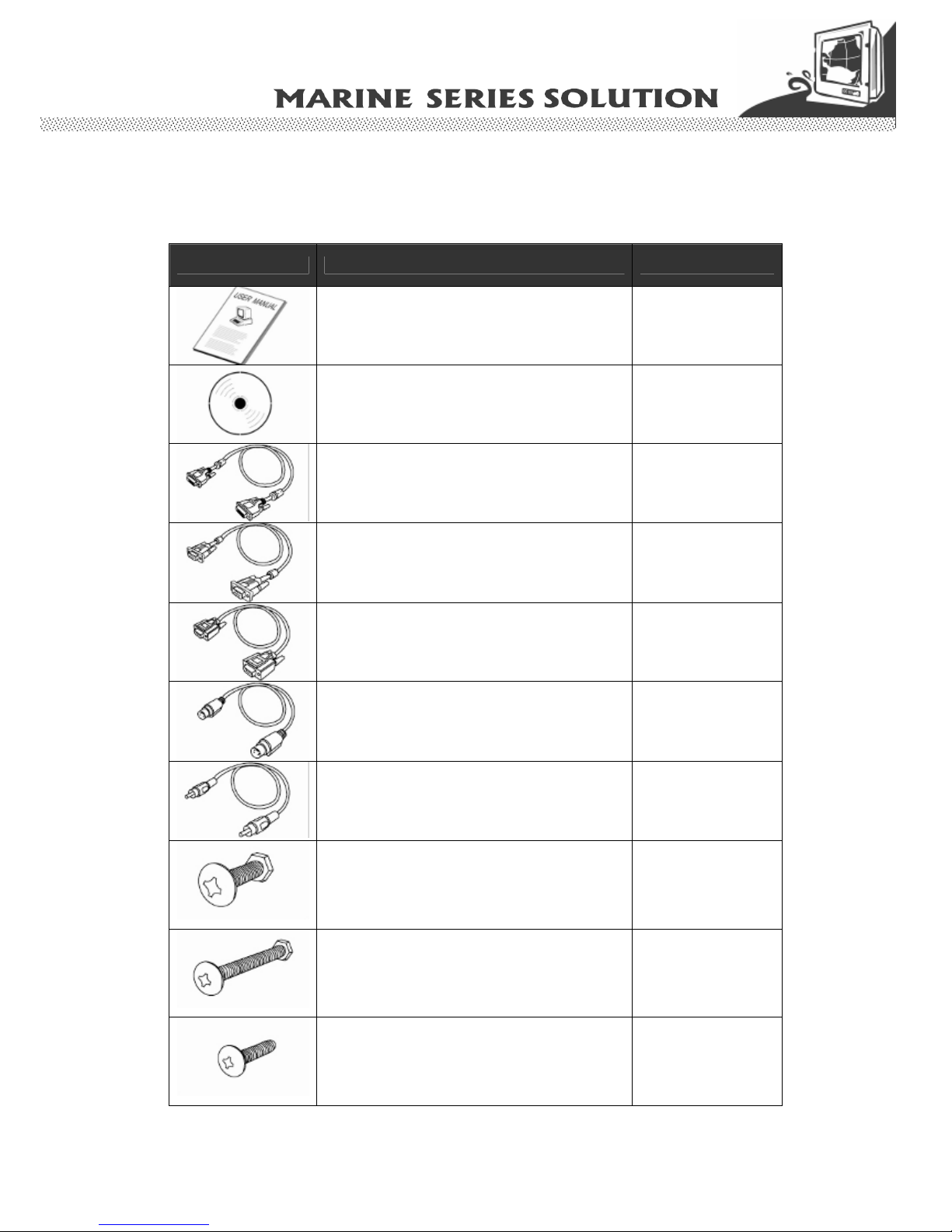
Packaging List
This product is shipped with the items list below. Please make sure that all are in your
package.
Item Description Note
1 pcs of Users Manual.
1 pcs of CD for Touchscreen Driver Tools.
1 pcs of DVI Cable.
DVI-D 24pin Male to 24pin Male: 1.5m.
10.4 inch above
1 pcs of Std VGA Cable.
D-SUB 15pin Male to 15pin Male: 1.8m
2 pcs of RS232 St d Serial Cable.
D-SUB 9pin Male to 9pin Female: 2m
1pcs for Touch use
1pcs for 10.4 inch
above display
remote control use.
1 pcs of S-Video Cable.
MD 4pin Male to 4pin Male: 1.8m
1 pcs of Composite Cable.
Std RCA 3.2mm connector: 1.8m
4 pcs of M6 x 30 black screw bolt with M6 nut.
Notice: Only be used to screw the display
into a console.
If you prefer your own bolts, please make sure
to use M6 and 30mm in length.
10.4 inch above
display use.
4 pcs of M4 x 30 black screw bolt with M6 nut.
Notice: Only be used to screw the display
into a console.
If you prefer your own bolts, please make sure
to use M4 and 30mm in length.
8.4 inch display use
M4 x 15 black screw bolt.
Notice: Only be used to screw the display
into a console from the rear side.
If you prefer your own bolts, please make sure
to use M4 and 30mm in length.
10 pcs for 8.4”,10.4”
12.1”; 12 pcs for 15”;
16 pcs for 17”, 19”,
20.1”, and 18 pcs
23.1” display use.
Users Manual Marine Bridge System Displays 4
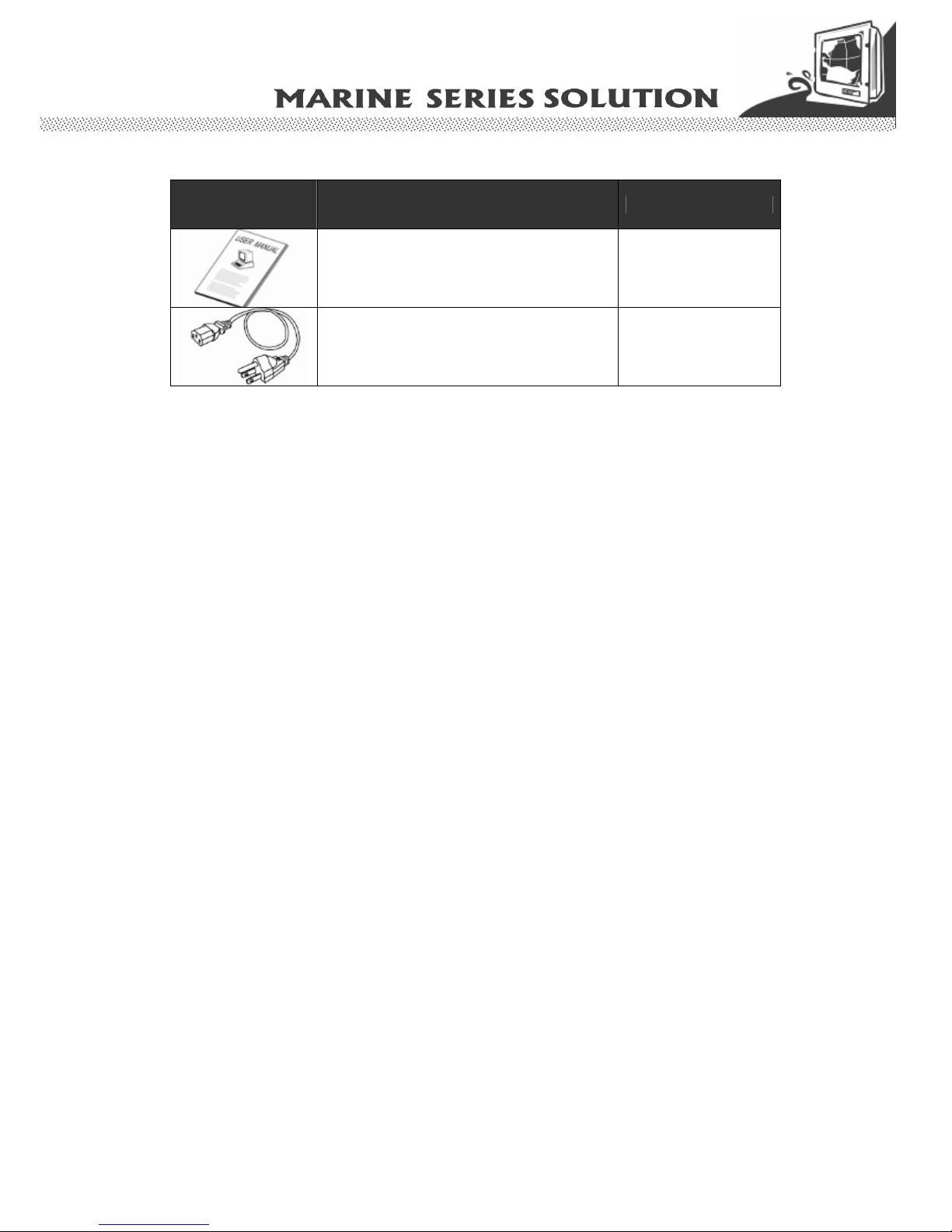
Optional Accessories
Item Description Note
1 pcs of Transflective LCD User Guide. Optional with
Transflective LCD
panel.
1 pcs of Stan dard Power Cord.
Euro / U.S. Std type, 1.8m
Optional AC version of
display use default.

Users Manual Marine Bridge System Displays 5
Contents
IMPORTANT SAFETY INSTRUCTIONS.........................................................2
PACKAGING LIST ..........................................................................................3
CHAPTER 1 GENERAL INFORMATION......................................................7
1.1 FEATURES ABOUT THE MARINE BRIDGE SYSTEM DISPLAY..........................................................7
1.2 BASIC CONSTRUCTION OF MARINE BRIDGE SYSTEM DISPLAY....................................................9
1.3 TOUCH SCREEN SOLUTION (OPTIONAL).....................................................................................10
1.3.1 Five-Wire Resistive Touch screen (Optional 1)....................................................................10
1.3.2 SecureTouch Surface Wave Touch screen (Optional 2).......................................................11
1.4 CERTIFICATE SERIAL NUMBER LABEL .......................................................................................12
CHAPTER 2 INSTALLATION .....................................................................15
2.1 GENERAL INSTALLATION .............................................................................................................15
2.2 INSTALLATION NOTICE................................................................................................................18
2.2.1 Brightness Control Knob Precaution...................................................................................18
2.2.2 Cable Connection Precaution...............................................................................................18
CHAPTER 3 OPERATION OF THE LCD DISPLAY ...................................20
3.1 INPUT / OUTPUT SIGNALS OVERVIEW .........................................................................................20
3.2 OSD USER CONTROLS.................................................................................................................22
3.3 PIP (PICTURE IN PICTURE) FUNCTION........................................................................................23
3.4 AUTO ADJUSTMENT FUNCTION ...................................................................................................23
3.5 SOURCE FUNCTION ......................................................................................................................24
3.6 OSD MENU FUNCTION.................................................................................................................25
3.6.1 Display Item Menu ...............................................................................................................26
3.6.2 Image Item Menu .................................................................................................................27
3.6.3 Position Item Menu..............................................................................................................30
3.6.4 Color Item Menu...................................................................................................................32
3.6.5 PIP Control Item Menu........................................................................................................34
3.6.6 Main Display Item Menu......................................................................................................35
3.6.7 PIP Display Item Menu........................................................................................................36
3.6.8 Audio Item Menu (Optional)................................................................................................37
3.6.9 Reset Item Menu...................................................................................................................38
3.7
SIMPLY ROUBLE SHOOTING GUIDE…………………………………… ......…………………….38
APPENDIX A: CLEANING THE MONITOR ..................................................40
APPENDIX B: DISCLAIMER AND TROUBLESHOOTING...........................41
DISCLAIMER.......................................................................................................................................41
TROUBLESHOOTING...........................................................................................................................41
APPENDIX C: SUPPORTED MODES ..........................................................42
APPENDIX D: RS-232 COMMAND CODE(OPTIONAL) ..............................43
APPENDIX E: SUNLIGHT READABLE (TRANSFLECTIVE) OUTDOOR
READABILITY (OPTIONAL).........................................................................44
Users Manual Marine Bridge System Displays 6
CHAPTER 1
General Information
Users Manual Marine Bridge System Displays 7
Chapter 1 General Information
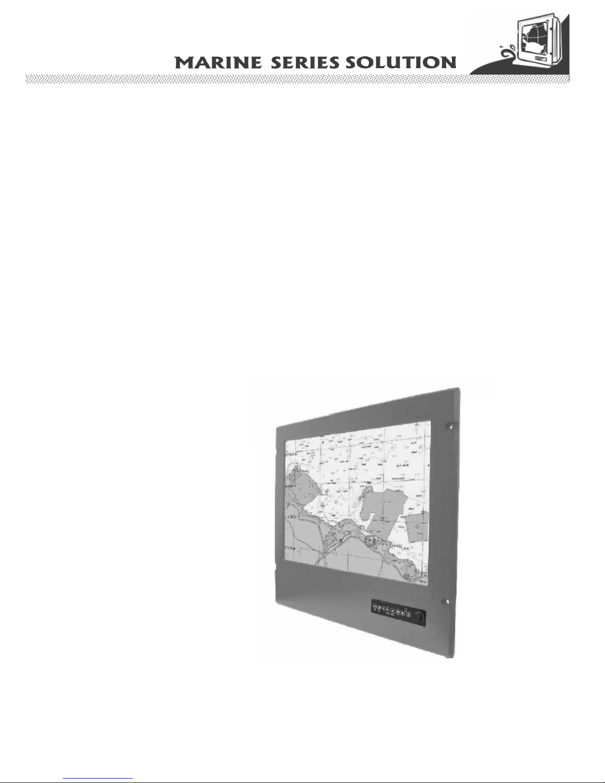
The Marine Bridge System Displays are an extraordinary display design with sunlight readable
high quality panel, dimming brightness, ease of use OSD front panel control, IP65 proof,
multi-scan video function, high quality touchscreen, wide voltage range power input
acceptable, and anti-corrosion protection. Born to the demands of maritime applications such
as navigation, ship automation and surveillance.
All product designs follow IEC-60945 Maritime Navigation and Radio-communication
Equipment and Systems requirements.
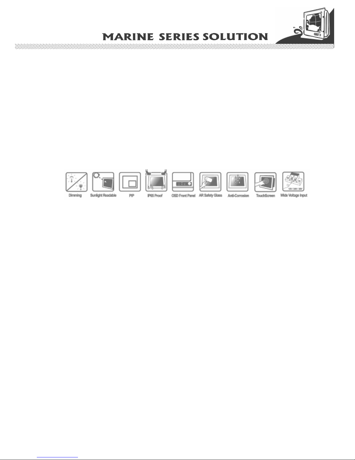
1.1 Features about the Marine Bridge System Display
Here are features of Marine Bridge System Displays:
Full-range durable displays
The Marine Bridge System Displays use high quality branding TFT LCD displays with high
resolution and wide temperature range panels. From 8.4 inch to 23.1 inch, we offer a wide
range choice fulfilling any demand in Marine market.
Hyper Dimming
Our displays use hyper dimming technology that can control backlight brightness linearly from
nearly 0% to 100% by a dimming knob. In the night vision it’s very suitable for marine
applications.
Sunlight Readable (Optional)
Our extraordinary transflective film technology enhances visibility for Marine outdoor or bright
ambience environment. (Outdoor readability please take reference to Appendix E)
Anti-corrosion IP Proof (Optional)
The Marine displays design with panel (flush) mount IP65 aluminum housing with powder
coating design (IP54 rear) achieve the anti-corrosion proof in harsh conditio ns.
Wide Voltage Input Range Power Input
For marine and transportation power source characteristic, our displays use wide voltage
range from 8 to 36V input acceptable. AC power input is also optional for several models from
12 inch to 23.1 inch.
For 12.1 inch to 23.1 inch display, the AC power source is also available for option.
Touchscreen / Anti-reflection Protection Glass
We develop highly compatible mechanical design for each type. Customers can choose high
quality SAW touchscreen, 5 wire resistive touchscreen, or even anti-reflection protection glass
for option.
Users Manual Marine Bridge System Displays 8
Multi-scan Function
The display can accept multi-video inputs as DVI, VGA, S-Video or Composite for example.
From 10.4 inch to 23.1 inch displays, our outstanding scaling board design also support PIP
(picture in picture) function for special marine applications.
IP65 OSD Front Panel Design
With IP65 water-dust front bezel proof, the Marine Bridge System Displays use easy to use
front panel OSD control. It’s very convenience and in telligent design for all maritime users.
Anti-Shock and Vibration
Enhanced shock and vibration resistance.
Customize your marine products
Base on our well-experience modulized competence, we can do very flexible and tailor-made
design fulfilling any of customer’s solution. For different panel characteristics, mechanical
design, and electronic component, we can make it for you.
Approved Marine Displays
Winmate Marine Bridge System Display design are all followed IEC-60945 Maritime
Navigation and Radio-communication Equipment and Systems requirements.
The Marine Bridge System Display series consists wide range sizes from 8.4 inches to 23.1
inches. By testing for usability in a ship’s wheelhouse during different ambient light
conditions. All these models can fulfill most of the demands in maritime applications
especially for navigation, ship automation and maritime surveillance.
About this Manual
The users’ manual introduce basic information about the product, electrical, mechanical and
input / output signal specifications. All specification are subject to change without prior notice
due to manufacturing reasons. Check in the “Revision History” in front page of this manual for
any update reference.
Users Manual Marine Bridge System Displays 9
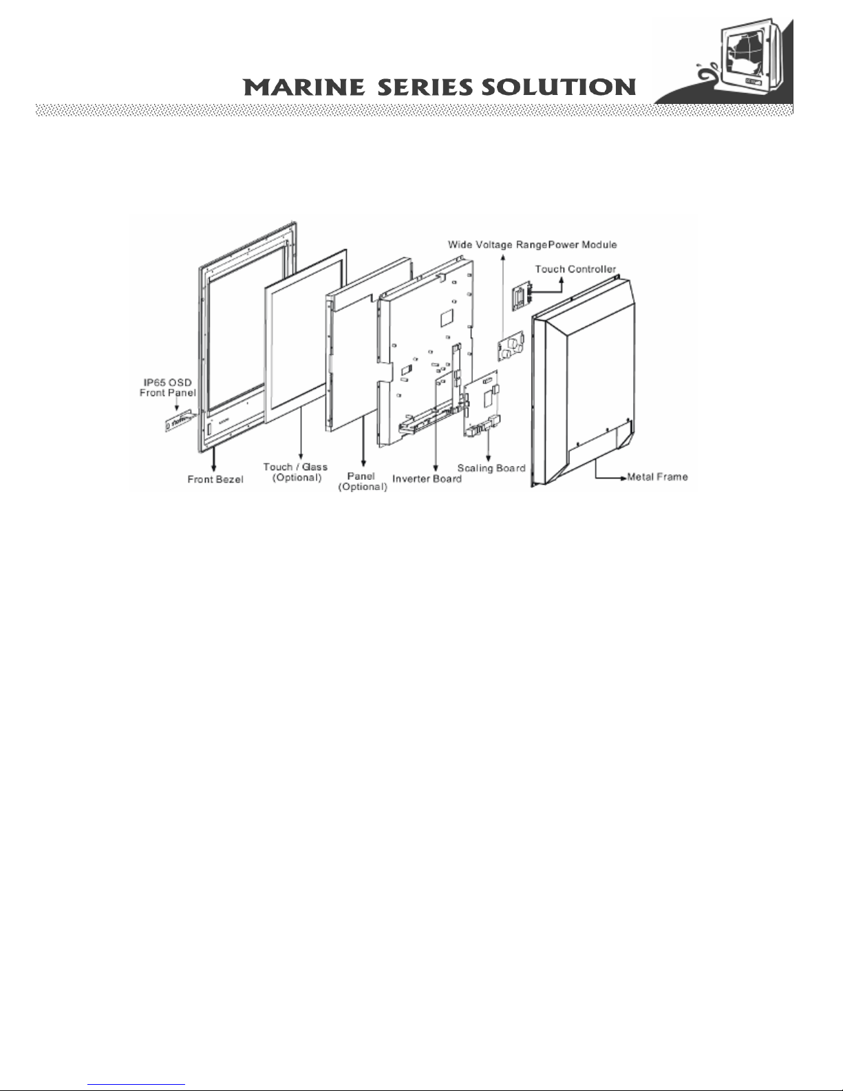
1.2 Basic Construction of Marine Bridge System Display
The state of the art modulized technology can integrate all marine display comp onents flexibly .
Figure 1.1 Basic Construction
Users Manual Marine Bridge System Displays 10
1.3 Touch Screen Solution (Optional)
1.3.1 Five-Wire Resistive Touch screen (Optional 1)
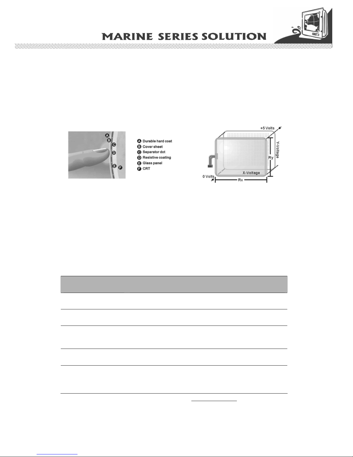
Introduction to Five-Wire Resistive Touch screen
The five-wire resistive touchscreens use a glass panel with a uniform resistive coating. A thick
polyester coversheet is tightly suspended over the top of the glass, separated by small,
transparent insulating dots. The coversheet has a hard, durable coating on the outer side and
a conductive coating on the inner side.
When the screen is touched, the conductive coating makes electrical contact with the coating
on the glass. The voltages produced are the analog representation of the position touched.
The controller digitizes these voltages and transmits them to the computer for proce ssing. The
five-wire technology utilizes the bottom substrate for both X and Y-axis measurements. The
flexible coversheet acts only as a voltage-measuring probe. This means the touchscreen will
continue working properly even with non-uniformity in the cover sheet's conductive coating.
The result is an accurate, durable and reliable touchscreen that offers drift free operation. The
touchscreens are sealed against contamination and moisture. The coversheet is sealed to the
glass substrate with an industrial grade caulk. This prevents wicking of fluid between the
coversheet and glass. Also, the touchscreens are not air vented, thereby preventing fluid
ingress through an air vent.
Brief Specifications
Subject Details
Input Method Finger, gloved hand, or stylus a ctivation
Positional Accuracy Standard deviation error is less than 0.080 (2 mm)
Resolution Touchpoint density is based on controller resolution of 4096 x
4096
Touch Activation Force Typically less than 4 ounces (113 grams)
Light Transmissi on HL products: 80% +/–5% at 550 nm wavelength
Enhanced products: 60% +/–5% at 550 nm wavelength
Update touchscreen driver or new information. Go to www.elotouch.com
Users Manual Marine Bridge System Displays 11
1.3.2 SecureTouch Surface Wave Touch screen (Optional 2)
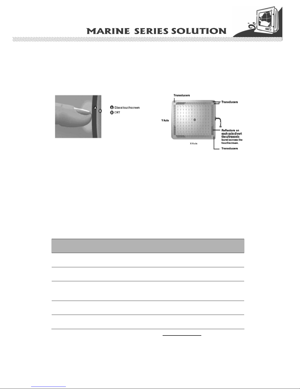
Introduction to SAW Touch screen
The surface wave is the optical standard of touch. Its pure glass construction provides sup erior
optical performance and makes it the most scratch-resistant technology available. It's nearly
impossible to physically "wear out" this touchscreen.
The touch have a glass overlay with transmitting and receiving piezoelectric transducers for
both the X and Y axes. The touchscreen controller sends a five-megahertz electrical signal to
the transmitting transducer, which converts the signal into ultrasonic waves within the glass.
These waves are directed across the front surface of the touchscreen by an array of reflectors.
Reflectors on the opposite side gather and direct the waves to the receiving transducer, which
reconverts them into an electrical signal—a digital map of the touchscreen surfa c e.
When you touch the screen, you absorb a portion of the wave traveling across it. The received
signal is then compared to the stored digital map, the change recognized, and a coordinate
calculated. This process happens independently for both the X and Y axes. By measuring the
amount of the signal that is absorbed, a Z-axis is also determined. The digitized coordinates
are transmitted to the computer for processing.
Brief Specifications
Subject Details
Input Method Finger or gloved hand (cloth, leather, or rubber) activation
Positional Accuracy Standard deviation of error is less than 0.080 in. (2 mm)
Resolution Touchpoint density is based on controller resolution of 4096 x
4096, plus 255 levels corresponding to touch pressure
Touch Activation Force Typically 2 to 3 ounces (55 to 85 grams)
Light Transmissi on Up to 90% per ASTM D1003-92
Update touchscreen driver or new information. Go to www.elotouch.com
Users Manual Marine Bridge System Displays 12
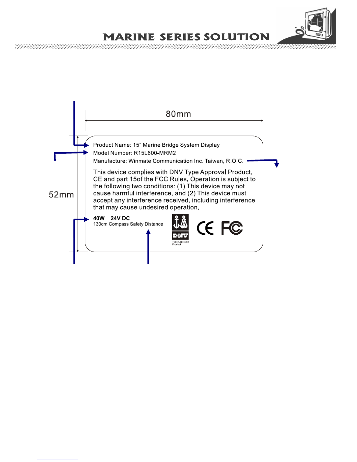
1.4 Certificate Serial Number Label
The certificate label and serial number for Marine products are de scribed as below.
Power Rating and
Input Voltage
Compass Safety
Distance
Product Description
Product and
Serial Number
Manufacturer
and Country
Users Manual Marine Bridge System Displays 13
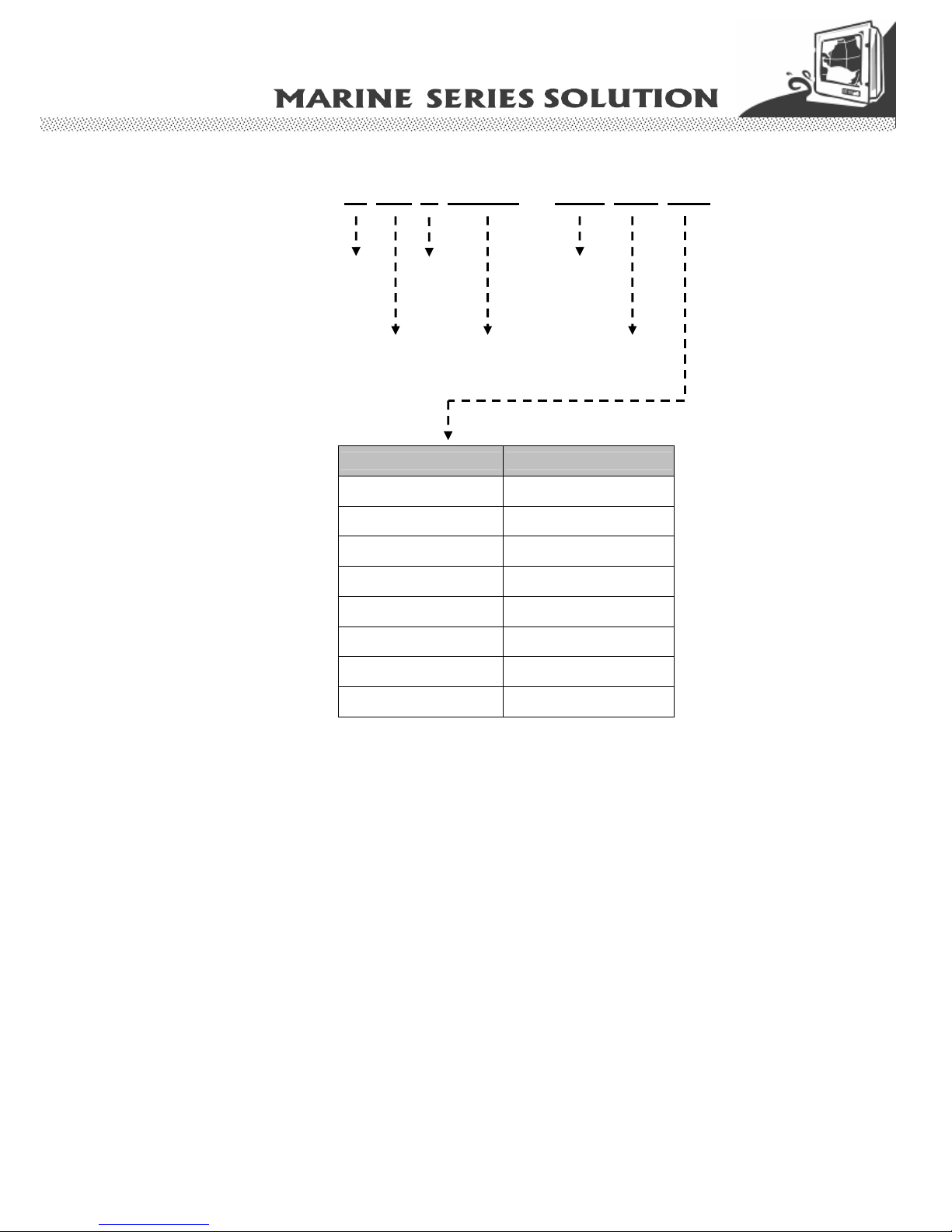
R 15 L 6 0 0 – MR M2 XX
Panel Type
Panel Size
Panel
Interface
Video
Function
Mechanical
Type
Panel
Model
Accessory Function
Additional Function Description
ITR IT touch w/ RS-232
ITU IT touch w/ USB
ATR AT touch w/ RS-232
ATU AT touch w/ USB
TR Transflective Panel
AR Anti-Reflection Glass
GS Protection Glass
WT Wide Temperature
Model Serial Number (For Marine Display)
 Loading...