

Marine audio MA400 User Manual
MA400
MARINE AUDIO SYSTEM
Installation and Operation Manual

MA400
CONTENTS
Introduction ............................................................................................................................... 2
Safety Information .................................................................................................................... 3
Installation ................................................................................................................................ 4
Wiring ....................................................................................................................................... 6
Basic Operation ........................................................................................................................ 7
Tuner Operation........................................................................................................................ 9
MP3/USB Operation ................................................................................................................ 11
SIRIUSXM Radio Operation .................................................................................................... 12
iPod® Operation ...................................................................................................................... 16
Bluetooth Operation ................................................................................................................ 17
APP Operation ........................................................................................................................ 18
Care and Maintenance ........................................................................................................... 19
Troubleshooting ...................................................................................................................... 19
Specifications ......................................................................................................................... 20
Copyrights and Trademarks
All related marks and logos are trademarks of Sirius XM Radio Inc. All rights reserved.
“Made for iPod” and “Made for iPhone” mean that an electronic accessory has been designed to
connect specifically to iPod or iPhone respectively, and has been certified by the developer to
meet Apple performance standards. Apple is not responsible for the operation of this device or
its compliance with safety and regulatory standards. Please note that the use of this accessory
with iPod or iPhone may affect wireless performance.
© Copyright 2016 ASA Electronics, LLC PATENT PENDING
1

MA400
INTRODUCTION
System Features
Features of Marine Audio MA400 mobile audio system include:
Full Dot Matrix LCD
AM/FM Tuner with 30 Presets (12AM, 18FM)
RBDS (Radio Broadcast Data Service) with PTY Search
SiriusXM-Ready (SiriusXM Connect Vehicle tuner and subscription sold separately)
USB Playback of MP3 and WMA files
iPod Ready (USB Interface)
Weatherband Tuner with SAME Technology
Mute
Bluetooth (Supports A2DP, AVRCP and ID3)
APP Ready
Pre-set Equalizer – 5 settings (User, Flat, Pop, Classical, Rock)
Electronic Bass, Treble, Balance and Fader Controls
Output Power 50W x 4
4-Channel Pre-amp Line Level Outputs (Front & Rear RCA)
2 Wire Power Supply
Auxiliary Audio Input (RCA)
Content List
Tuner Amplifier Module
Wired Commander
Wired Commander Cover
10’ Wired Commander Extension Cable
Power Harness
Stainless-steel tapping screws (4)
Quick Reference Guide
2

MA400
SAFETY INFORMATION
When Boating
Keep the volume level low enough to be aware of your surroundings.
Protect from Water
Do not submerge or expose the product directly to water, as this can cause electrical shorts, fire
or other damage
Protect from High Temperatures
Exposure to direct sunlight for an extended period of time can produce very high temperatures
inside your vessel. Give the interior a chance to cool down before starting playback.
Do not mount radio with close proximity of engine compartment.
Use the Proper Power Supply
This product is designed to operate with a 12 volt DC negative ground battery system.
WARNING:
DO NOT OPEN, DISASSEMBLE OR ALTER THE UNIT IN ANYWAY. Doing so may result
in fire, electric shock or product damage.
USE THE CORRECT AMPERE RATING WHEN REPLACING FUSE. Failure to do so may
result in fire, electric shock or product damage.
DO NOT INSTALL IN LOCATIONS THAT MIGHT HINDER VEHICLE OPERATION. Doing
so may obstruct vision or hamper movement which can result in a serious accident.
INSTALL THE WIRING SO THAT IT IS NOT CRIMPED OR PINCHED BY SCREWS OR
SHARP METAL EDGES. Route the cables away from moving parts or sharp pointed
edges. This will prevent crimping and damage to the wiring. If the wiring must pass
through a metal hole, be sure to use a rubber grommet to prevent the wire’s insulation
from being cut by the metal edge of the hole. It is also recommended to apply sealing
caulk to any opening that may potentially allow water to enter.
Be sure to choose a location that is flat and has clearance above the unit to prevent any
damage, as well as allow for ventilation
Before drilling any holes, carefully inspect the area underneath and behind the mounting
surface where the devices will be mounted to make sure it will not interfere with existing
wires, fuel lines, the fuel tank or any other objects that could be damaged.
Always disconnect the vehicle negative battery terminal to prevent accidental shorting
during installation.
3
MA400
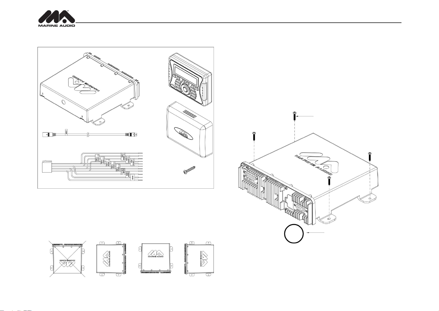
7/8” HOLE IS REQUIRED
M4 MOUNTING SCREWS (4-PCS)
MINIMUM SCREW LENGTH 1 1/2”
M5 x 8 SCREWS REQUIRED
7/8” HOLE IS REQUIRED
INSTALLATION
Before you Begin
Before you begin, always disconnect the battery negative terminal.
Important Notes
Before final installation, test the wiring connections to make sure the unit is connected
properly and the system works.
Use only the parts included with the unit to ensure proper installation. The use of
unauthorized parts can cause malfunctions.
Consult with your nearest dealer prior if installation required the drilling of holes or other
modifications to your vessel.
Install the unit where it does not interfere with driving and cannot injure passengers if there
is a sudden or emergency stop.
Avoid installing the unit where it will be subject to high temperatures from direct sunlight,
hot air, or from a heater, or where it would be subject to excessive dust, dirt or vibration.
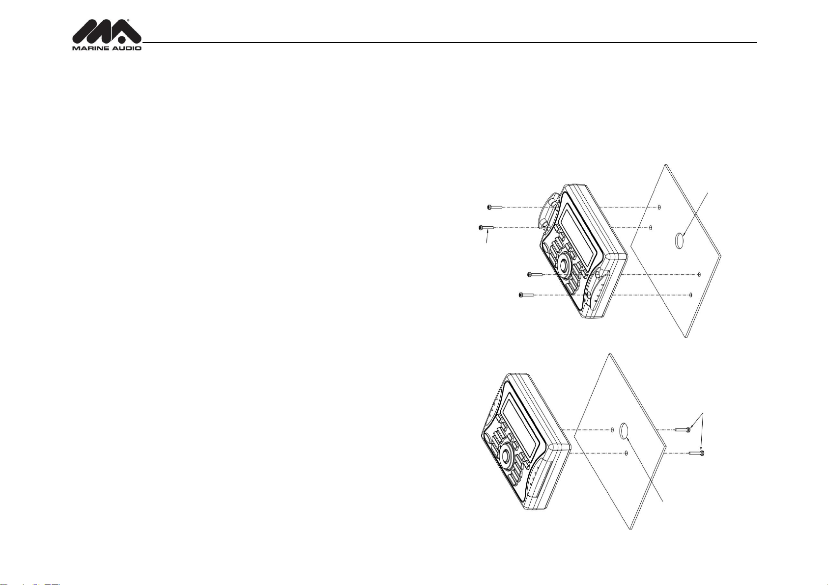
Wired Commander Mounting
1. Choose a mounting area for the wired commander that is clean and flat, allowing the rear
gasket to fully seal to the mounting surface
2. Secure the wired commander using either of the recommended mounting methods
detailed in the diagrams below.
FOR CABLE
FOR MOUNTING
MAXIMUM SCREW DEPTH IN
COMMANDER 1/4”
FOR CABLE
4
MA400
1 3/4” HOLE REQUIRED FOR CABLE/CONNECTOR
STAINLESS STEEL #8 SCREWS REQUIRED
WITH MINIMUM LENGTH OF 1”
1/8” PILOT HOLES FOR SUPPLIED SELF-STARTING SCREWS
.180 PILOT HOLES WHEN USING THREADED MACHINE SCREWS
TUNER AMPLIFIER
MODULE
WIRED
COMMANDER
WIRED
COMMANDER
COVER
POWER HARNESS
10 FOOT WIRED COMMANDER EXTENSION CABLE
STAINLESS
STEEL TAPPING
SCREW (x4)
Hardware Kit Contents
Tuner/Amplifier Mounting
1. Choose a mounting area for the tuner/amplifier module that will provide plenty of
ventilation to prevent the amplifier from overheating. The tuner/amplifier module can be
mounted in the horizontal or vertical position. Please note that when mounting in vertical
position, do not mount with the harness exit points facing straight up, as water can collect
around the chassis in these areas.
2. Using the shortest length of the recommended size screws possible, mount the
tuner/amplifier as detailed in the diagram on the right.
3. Route the tuner/amplifier harness and cable throughout the vessel as required. Keep
some slack in the harness/cables so it won't be too tight, as this can cause damage to the
wires.
4. Follow the wiring diagram carefully and make certain all connections are secure and
insulated with crimp connectors or electrical tape to ensure proper operation.
5. After completing the wiring connections, reconnect the negative terminal of the battery
and turn the unit on to confirm operation (vessel accessory switch must be on). If the unit
does not operate, disconnect battery, recheck all wiring and refer to the trouble-shooting
guide located in the back of the manual.
Reconnect Battery
When wiring is completed, reconnect the battery negative terminal.
5
MA400
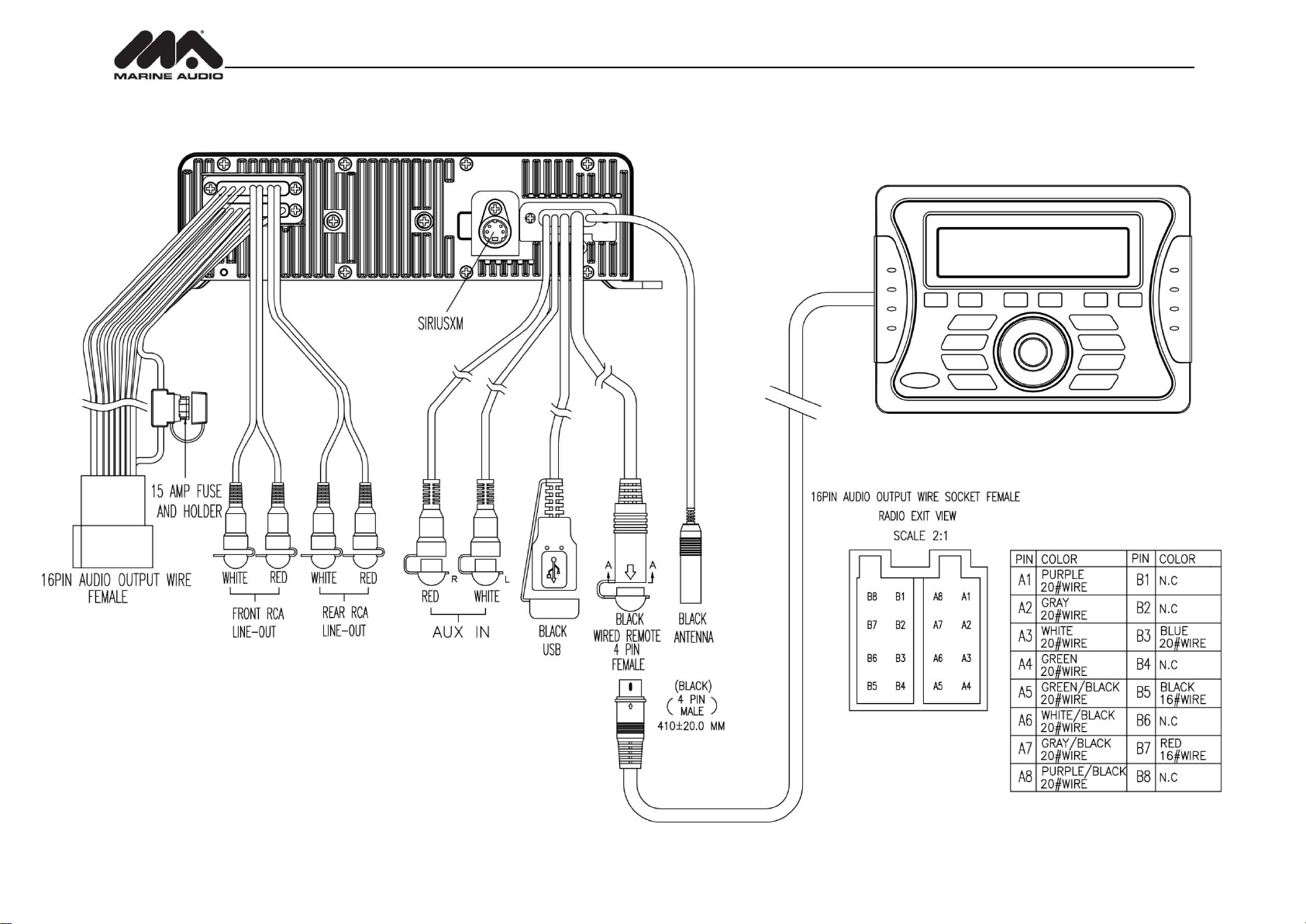
TUNER/AMP MODULE
WIRED COMMANDER
WIRING
6
 Loading...