

marinco INV20120700, INV30120700, INV10121000, INV20121000, INV10121500 User Manual
...
USER’S MANUAL
INV10120700 / INV20120700 / INV30120700
INV10121000 / INV20121000 / INV10121500
INV20121500 / INV30121500 / INV10240700
INV20240700 / INV10241000 / INV10241500
INV20121500
Pure sine wave inverter
10000006303/05
MARINCO
N85W12545 Westbrook Crossing
Menomonee Falls, WI 53051
www.marinco.com
ENGLISH: PAGE 1
NEDERLANDS: PAGINA 13
DEUTSCH: SEITE 25
FRANÇAIS: PAGINA 37
CASTELLANO: PÁGINA 49
ITALIANO: PÁGINA 61
2
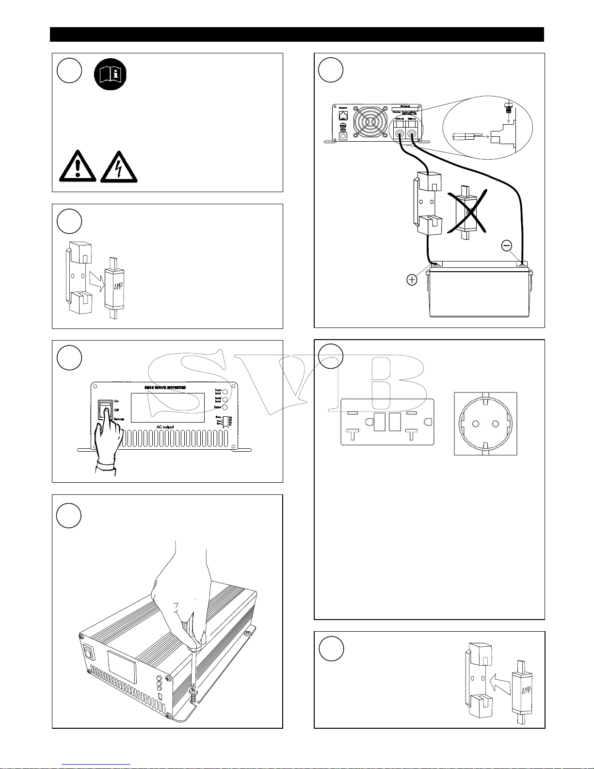
ENGLISH QUICK INSTALLATION INSTRUCTIONS
7
Check all wiring. If all wiring is
OK:
Place the inverter fuse.
Switch on the Inverter.
6
Connect the AC load to the AC socket.
For safe installation,
The chassis ground terminal (see Figure 1,
reference 7) must be connected to the central
grounding point of the vehicle/ ship
The neutral conductor (N) of the AC output of
the Inverter must be connected to the safety
ground (PE/GND) and a ground fault circuitinterrupter (GFCI) must be integrated in the
wiring of the AC output
Refer to section NEUTRAL GROUNDING of this
user’s manual
120V: 230V:
Move the main switch of the Inverter to
the OFF position
3
5
Connect the battery to the DC input.
Integrate a fuse holder in the positive
battery wire, but do not place the fuse yet.
Black wire
NEG
(
–
)
Red wire
POS (+)
Connect
red wire to +,
black wire to –.
Incorrect polarity
will damage the
Inverter!
Mount the Inverter with four screws to a solid
surface. Allow at least 10 cm / 4 inch space
around the apparatus!
4
Disconnect the electrical power:
Switch off all consumers,
Switch off all charging
systems.
Remove the battery fuse.
Check with a suitable
voltmeter whether the DC
installation is voltage free.
2
1
This section provides a brief
overview of a basic stand alone
installation of the Inverter
However; please review the entire manual for
connection of additional features and to ensure
best performance and years of trouble-free
operation.
Use isolated tools!
Read safety instructions
(page 3)
3
USER’S MANUAL 700, 1000, 1500 WATT INVERTER ENGLISH
PRODUCT DESCRIPTION AND APPLICATION
The Marinco inverters convert a DC voltage to a pure AC
sine wave voltage.
SAFETY INSTRUCTIONS
WARNING!
Before using the Inverter, read and save the
safety instructions
Use the Inverter following the instructions and
specifications stated in this manual.
Connections and safety features must be executed
according to the locally applicable regulations
Operation of the Inverter without proper grounding
may lead to hazardous situations!
Use DC-cables with an appropriate size. Integrate a
fuse in the positive wiring and place it nearby the
battery. Refer to the specifications.
If the positive and negative wires on the DC-input
(battery) are exchanged, the Inverter will be damaged.
Damage of this kind is not covered by guarantee.
Check whether all connections are connected
correctly before placing the fuse.
Do not connect the AC-output of the inverter to an
incoming AC source.
Never connect the Inverter in parallel with any other
inverter.
Never open the housing as high voltages may be
present inside!
UNPACKING
The delivery consists of the following parts:
The inverter
This user’s manual
Four ring terminals
After unpacking, check the Inverter for possible damage.
Do not use the Inverter if it is damaged. If in doubt,
contact your supplier.
NEUTRAL GROUNDING
For safe installation,
The chassis ground terminal (see Figure 2, ref. 7)
must be connected to the central grounding point of
the vehicle/ ship
The neutral conductor (N) of the AC output of the
Inverter must be connected to the safety ground
(PE/GND) and a ground fault circuit-interrupter (GFCI)
must be integrated in the wiring of the AC output. See
below for model specific information.
Refer to locally applicable regulations on these issues!
120V models
With the 120V models the neutral conductor of the AC
output circuit of the Inverter is internally connected to the
safety ground during inverter operation automatically and
a ground fault circuit-interrupter (GFCI) is already
integrated in the AC output circuit of the Inverter.
230V models
With the 230V models there is no connection made inside
the inverter between either the line or neutral conductor
to the safety ground.
DIP SWITCH SETTINGS
See Figure 1, ref. 6. Under normal circumstances there is
no need to change the default settings of the DIP
switches: the inverter is immediately ready for use.
To save energy from the battery in no load operation, DIP
switches S1, S2 and S3 can be used to adjust the Power
Saving Mode. The Power Saving Mode scans the output
and when it detects a load which is higher than the
selected threshold value, the inverter is switched on
automatically.
Power Saving Mode S1 S2 S3
Model 700 1000/1500
DISABLE DISABLE 0 0 0
15W 20W 1 0 0
25W 40W 0 1 0
40W 55W 1 1 0
50W 75W 0 0 1
65W 95W 1 0 1
75W 115W 0 1 1
85W 135W 1 1 1
DIP switch S4 is used to select the output frequency
Output frequency S4
50Hz 0
60Hz 1
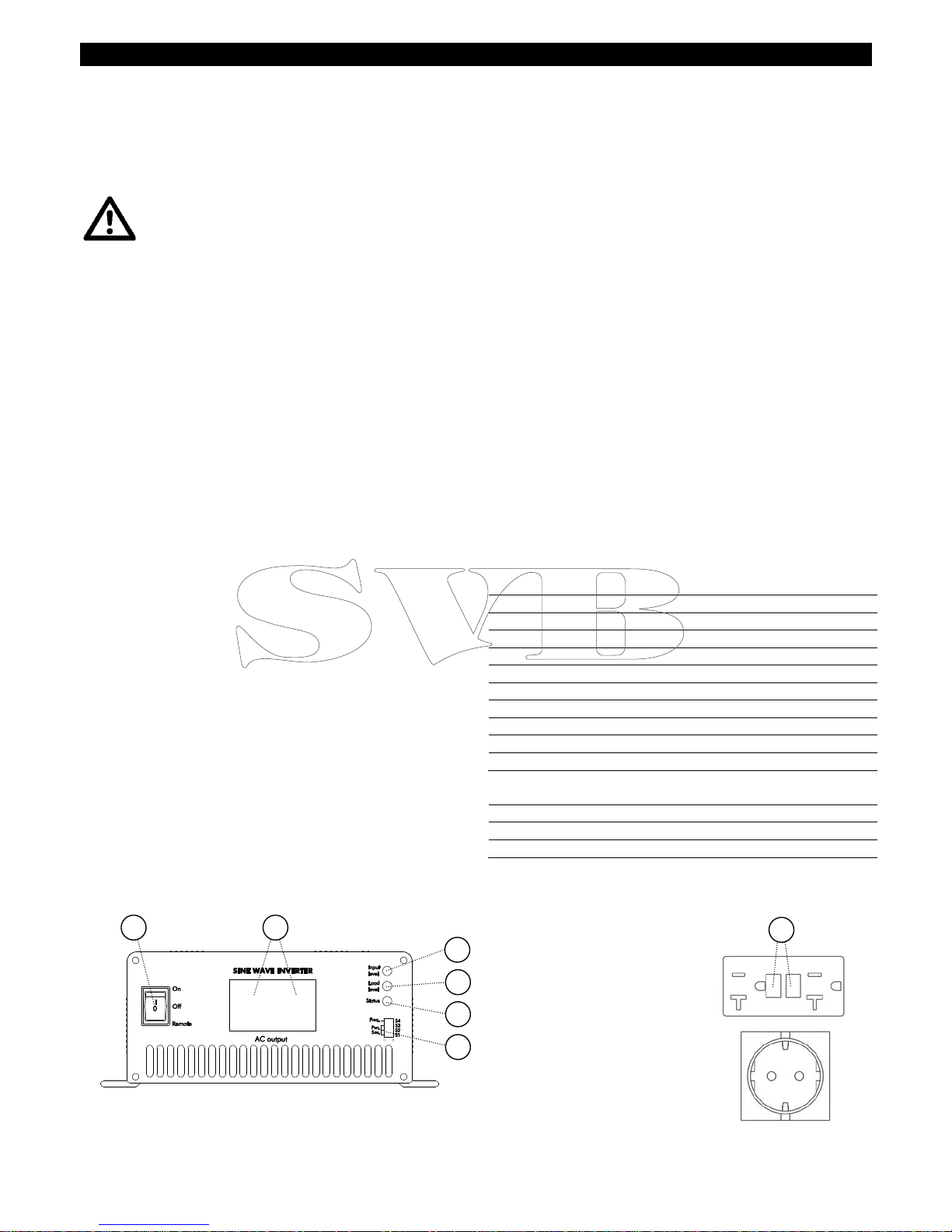
Figure 1: Front side
2
3
4
5
6
1
LED indicators
AC output
Main switch
DIP switches
R
AC output
120V models:
AC output
230V models:

4
ENGLISH USER’S MANUAL 700, 1000, 1500 WATT INVERTER
INSTALLATION
Choosing a location to install
Install the Inverter in a well-ventilated room protected
against rain, snow, spray, vapour, bilge, moisture and
dust.
Ambient temperature: –25 ... 40°C / –13…104°F;
Never use the Inverter at a location where there is
danger of gas or dust explosions
Mount the Inverter in such a way that obstruction of
the airflow through the ventilation openings is
prevented. No objects must be located within a
distance of 10 cm / 4 inch around the Inverter.
Do not install the Inverter in the same compartment as
the batteries. Do not mount the Inverter straight above
the batteries because of possible corrosive sulphur
fumes.
Before you start
Be sure that the output of the supplying source
(battery) is switched off during installation. Also be
sure that no consumers are connected to the battery
during installation, to prevent hazardous situations.
Before installing the Inverter make sure the main
switch (Figure 1, ref. 1) is set to the OFF position.
Check that the battery voltage is the same as the
input voltage of the Inverter (e.g. 24V battery for a
24V input voltage). Also check that the output voltage
satisfies loading requirements
A DC fuse holder must be integrated in the positive
wiring. The DC fuse should be placed last of all.
Use four Ø4.5mm (No. 8) screws to mount the
Inverter to a solid surface. See Figure 3.
Wiring
Connect DC wiring as shown in Figure 2: the black
terminal (9) NEG (–) to the negative (–) pole of the
power source / battery, the red terminal (8) POS (+) to
the positive (+) pole of the power source/ battery.
Integrate a DC fuse holder in the positive wiring, but
do not place the fuse yet. Assemble the DC wiring
exactly as indicated. Do not place anything between
the ring terminal and the terminal surface. Make sure
that all DC connections are tight. Recommended
torque: 11.7-13 Nm / 104-115 InLbs
Chassis ground: Use a cable AWG8 / 6 mm² to
connect the CHASSIS GROUND terminal (7) to the
central ground.
Remote operation switch (option). If you want to
operate the Inverter on a remote location, you can
install a switch as indicated in Figure 2. When the
contact is closed, the Inverter is switched on.
Inverter
Fuse holder + Fuse
Grounding
point
Black wire NEG (–)
Remote operation
switch (option)
Battery
OFF
ON
9
10
7
8
Red wire POS (+)
Figure 2: rear side
 Loading...