

marinco 772-DBC, 772-DBC-B Instruction Manual
Dual Bank Control Battery Switch
772-DBC 400A Dual Bank Control (Retail Packed)
772-DBC-B (Bulk Packed)
www.bepmarine.com | www.mastervolt.com | www.marinco.com
Features & Benefi ts:
• Industry standard footprint
• Three mounting options – surface, rear-panel and front-panel
• Compatible with metric and imperial mounting fasteners
• User friendly design
• Improved access for cables
• Removable knob for isolation/safety
• Includes back cover and three side panels for security and cable protection
• Designed to withstand harsh marine environments
• High temperature reinforced plastics
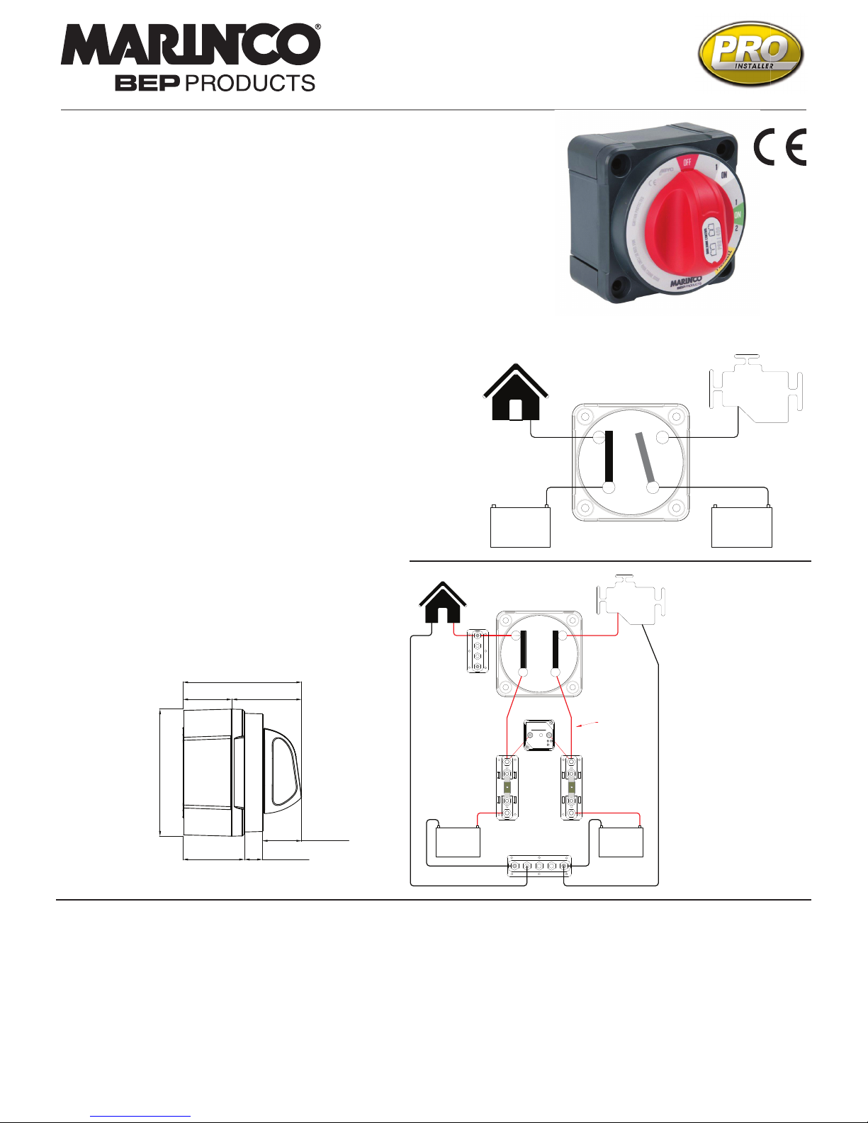
1 2
Loads
Engine
Battery
1
Battery
2
Loads
+ +
Isolated Safety
Position: “1
Dual Bank Control Switch
Specifi cations:
• Continuous rating: 400A*
• Intermittent rating: 600A* (5min)
• Cranking rating: 1500A* (10sec)
• 12-48V DC (Higher voltage applications on request)
• Connection stud size: M10 (3/8”)
• IP66 – protection from powerful water jets
• Ignition protected
• Independently tested to meet UL1107 standards
• CE marked
*Electrical ratings achieved using cable size 120mm²
• It is recommended that electrical terminations and connections are
carried out by a marine electrical technician.
• Negative terminations, and Positive terminations must be to the same
numbered studs i.e. both Negatives must be connected to studs numbered “1”, or both Negatives connected to studs numbered “2”. Failure
to do this will result in short circuit or fi re!
• These battery switches are for isolation purposes and are not designed
for switching under load. Ensure there are no circuits with high
inductive loads directly connected to the switch in order to prevent any
sudden in-rush of current which may cause damage to the switch.
• Although specially selected chemical resistant materials have been
used, it is recommended that for maximum product life only plastic
safe corrosion inhibiting sprays are used.
• Ensure all cables are sized correctly for the loads they carry - refer to
www.bepmarine.com to calculate correct cable sizes.
• Ensure all electrical connections are correctly tightened to prevent any
damage to the battery switch.
5 YEAR WARRANTY
1 2
Loads
Engine
Start
Battery
+
-
+
-
House
Battery
DVSR
Loads
Positive
Bus
Negative
Bus
House
Battery
Fuse
Optional
Start
Batt
Fuse
DVSR (710-140A)
provides automatic
battery charging
of second bank
Example System:
NOTE -This
diagram is a
guide only showing
Dual Bank Control
Switch onnections
and is not intended
as a full electrical
systems wiring
diagram.
47.7 [1.88] 13.9 [0.55]
30.4 [1.20]
97.8 [3.85]
91.9 [3.62]
38.0 [1.50] 53.9 [2.12]
This innovative (patent pending) switch combines the functionality of three battery switches (House,
Start & Emergency Parallel) into one by simultaneously controlling two battery banks and two loads.
In the unlikely case of engine malfunction, a unique safety position isolates one load (e.g. House
ON/Start OFF) so emergency radios call can be made. With improved access for cabling and three
mounting options, the 772-DBC battery switch offers signifi cant savings in space and installation time.
Installation Instructions: IMPORTANT! Read before installing
Surface Mount Instructions
1. Choose mounting location on a flat surface close to the batteries
2. Select panhead (or similar) screws for mounting - use either M5 or 10g imperial (not included)
3. Knock or drill out plastic skin from screw holes in backplate
4. Select panhead (or similar) machine screws and nuts to secure switch to backplate - use either M6 x 40mm or 0.25 x 1.5”
(not included). Alternatively longer screws should be used if bolting all the way through the bulkhead/surface
5. Place nuts for machine screws into nut recesses, then screw backplate into position
6. Connect cables to studs ensuring that batteries and loads are correctly fitted
7. Check that spring washers are fitted beneath nuts
8. Tighten the stud nuts to 13.5 Nm (10 lbf)
9. Slot the side panel(s) into the backplate as required
10. Clip battery switch and cable assembly into backplate
11. Secure switch in place with machine screws, engaging into nuts under backplate
12. Ensure cables are secured to ISO/ABYC standards, and that cables are supported so they are not
placing unnecessary strain on the battery switch studs (see diagram)
13. With switch in “OFF” position connect battery positive leads at battery
14. Check switch operation (as per below)
Panel Mount Instructions
1. Choose mounting location
2. Ensure positive leads are removed from battery banks
3. Use the mounting template (shown below) to mark hole positions
4. Drill four machine screw holes and the 92mm (or 3 5/8”) hole for the switch body.
5. Front panel mounting only: either recess for the four clipping features (see template) or cut/file off these features
from the battery switch plate
6. Mount switch to panel using M6 (or 0.25”) machine screws – note: use either pan or cheesehead screws only
7. Connect cables to studs ensuring that batteries and loads are correctly fitted
8. Check that spring washers are fitted beneath nuts
9. Tighten the stud nuts to 13.5 Nm (10 lbf)
10. Rear panel mounting only: back plate and side panels can also be clipped to the switch for cable protection/insulation
11. Ensure cables are secured to ISO/ABYC standards, and that cables are supported so they are not placing strain on the battery
switch studs (see diagram)
12. With switch in “OFF” position connect battery positive leads at battery
13. Check switch operation (as per below)
Check switch operation:
1. Ensure loads have no voltage when in red “OFF” position
2. Ensure the correct load has voltage when in white “1-ON” position (e.g. House Load has connection to House Battery,
Start Load is isolated)
3. Ensure both loads have voltage but are separated when in green “1-ON-2” position
4. Ensure loads share common voltage when in yellow “PARALLEL” position
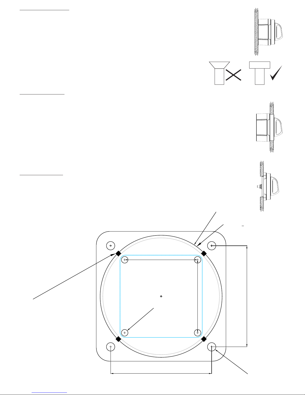
Mounting Template
Surface Mount Screw Holes
For Backplate
55.0 [2.17]
55.0 [2.17]
76.2 [3.00]
76.2 [3.00]
5.0 [0.20]
6.4 [0.25]
92.0 [3.62]
Use 3
5
8
"
holesaw
47.7 [1.88] 13.9 [0.55]
30.4 [1.20]
97.8 [3.85]
91.9 [3.62]
38.0 [1.50] 53.9 [2.12]
Clipping feature:
• Either remove clipping
features or recess panel
when front panel mounting
SURFACE
MOUNT
REAR
PANEL
MOUNT
FRONT
PANEL
MOUNT
REAR
PANEL
MOUNT
FRONT
PANEL
MOUNT
FRONT
PANEL
MOUNT
Please check scale
before using
Panhead
Cheesehead
Sockethead
T
O
R
Q
U
E
 Loading...