

Page 1
1
USE AND MAINTENANCE MANUAL
EN
428000692237 MARIN
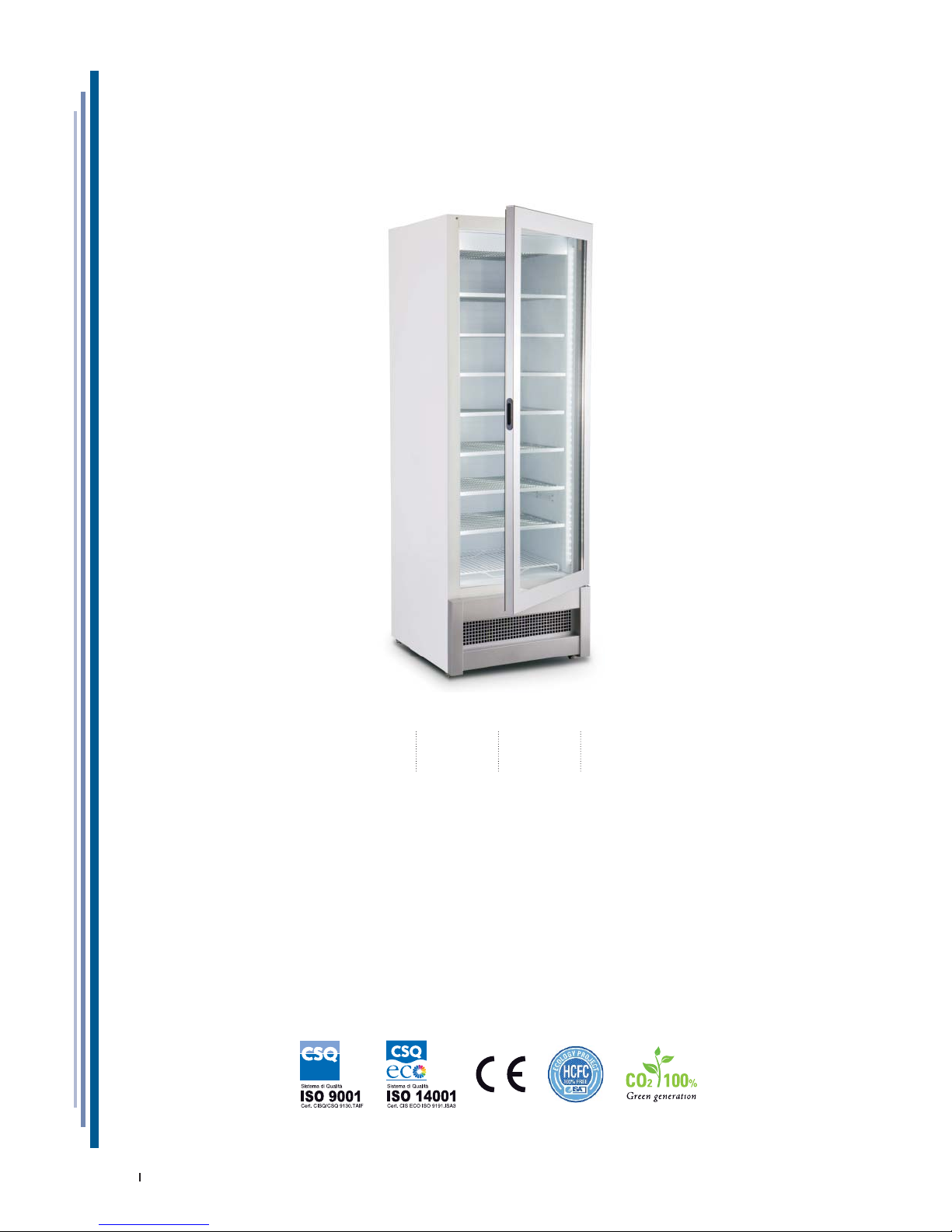
340 470
MARIN
ISA
Bastia Umbra - Perugia
Italy
Tel. +39 075 80171
Fax +39 075 8000900
www.isaitaly.com
Page 2
2
USE AND MAINTENANCE MANUAL
EN
428000692237 MARIN
1. NOTES / WARNINGS 4
2. MANUFACTURER 10
3. WARRANTY TERMS AND CONDITIONS 10
4. EQUIPMENT IDENTIFICATION 10
5. USE 11
5.1 COMPOSITION 11
6. SAFETY 12
6.1 SAFETY DEVICES PRESENT 12
6.2 FIXED PROTECTIONS 12
6.3 ISOLATING THE ELECTRIC POWER SUPPLY 12
6.4 RESIDUAL RISKS 12
6.5 RISK OF CONTACT WITH LIVE PARTS 12
6.6 FIRE 12
6.7 EXPLOSIVE ATMOSPHERE 13
6.8 SLIPPING 13
6.9 TRIPPING 13
6.10 CIRCUIT FAULTS 13
6.11 WARNING SIGNS (IF ANY) 13
6.12 FALLING OBJECTS 13
6.13 COOLING 13
6.14 FOODSTUFFS SAFETY (PACKAGED PRODUCTS) 13
7. DISPOSAL OF WASTE MATERIAL 14
8. INSTALLATION 15
8.1 STORAGE AND UNPACKING 15
8.2 ENVIRONMENTAL CONDITIONS 15
8.3 INSTALLATION 15
8.4 POSITIONING 16
8.5 ELECTRICAL CONNECTION 16
9. MAINTENANCE 17
10. FAULTS - TECHNICAL AFTER-SALES ASSISTANCE 18
10.1 ALARMS LIST (IF PRESENT) 19
11. TECHNICAL SPECIFICATIONS 20
11.1 MAX LOAD ON SHELVES / GRIDS 21
11.2 GRIDS (RV) 21
11.3 LIGHTING 22
12. CONTROL PANEL 23
12.1 USER INTERFACE PJ EASY 24
12.2 USER INTERFACE EW978 25
13. CLEANING 26
13.1 INTERNAL 26
13.2 CONDENSING UNIT 27
13.3 DEFROST WATER COLLECTION TRAY (IF PRESENT) 27
14. PROLONGED APPLIANCE SWITCH-OFF 27
Page 3
3
USE AND MAINTENANCE MANUAL
EN
428000692237 MARIN
ATTACHMENTS
1 WIRING DIAGRAM - 412100731000 28
2 WIRING DIAGRAM - 412100771000 29
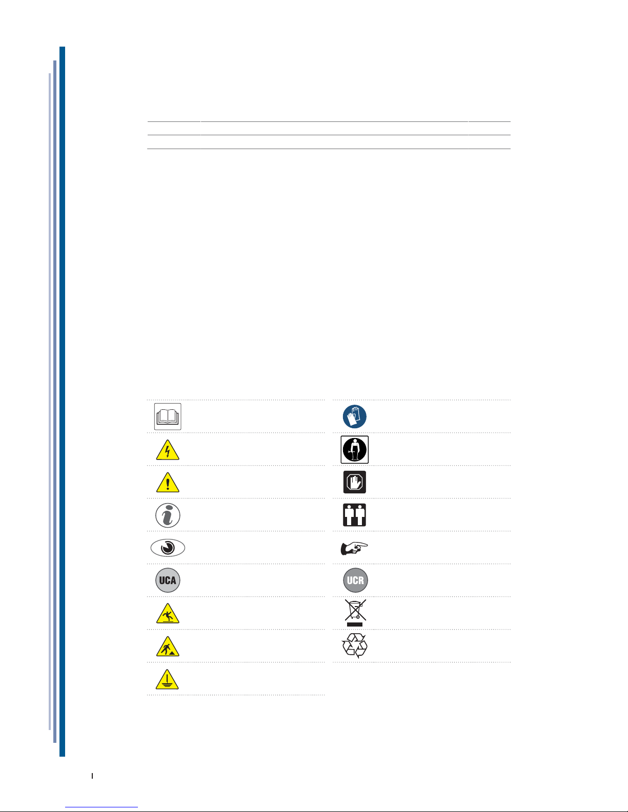
The manual contains symbols to attract the reader’s attention and highlight particularly
important aspects. The table below illustrates the meaning of the various symbols used.
Read the manual Use of protective clothing
DANGER
Live electrical parts
Requests for maintenance or operations must
be carried out by qualifi ed staff or technical
after-sales centres
ATTENTION / DANGER Important information
Information
Operations that must be performed by two
persons
Visual check NOTES / WARNINGS
On-board Condensing unit Remote Condensing unit
DANGER
Slipping
Waste disposal
DANGER
Tripping
Recyclable materials
Earthing
Page 4

4
USE AND MAINTENANCE MANUAL
EN
428000692237 MARIN
NOTE
The content of this manual is of technical nature and is owned by ISA.
It is forbidden to reproduce, circulate or modify all or part of its content
without written consent. Any infringement will be legally pursued.
The manual and the conformity certifi cate are an integral part of the equipment
and should always accompany the product in the event of a transfer to a new
location or to a new owner. The user is responsible for the integrity of these
documents, for their consultation and during the whole life cycle of the equipment
itself. Keep this manual in a safe place.It should be available for consultation
near the equipment at all times. If lost or destroyed, you can request a copy of
the manual from ISA by specifying the exact model, serial number and year of
manufacture. The manual refl ects the manufacturing technology at the time of
supply.The manufacturer reserves the right to modify its products in any way it
deems necessary, with no obligation to update manuals and machines relating to
previous manufacturing batches.
The equipment can be used by children no younger than 8 and by persons
with reduced physical, sensorial or mental capabilities, or lacking experience or
necessary knowledge, as long as supervised or after having received training
regarding safe use of the equipment and have an understanding of the inherent
risks involved. Do not allow children to play with the device. The cleaning and
maintenance that the user will carry out must not be undertaken by children
without supervision.
Always refer to this manual before going ahead with any operation. Before doing
any type of work, disconnect the equipment from the power supply. Any work on
electric and electronic parts or cooling system components should only be carried
out by trained personnel in compliance with current laws.
The Manufacturer cannot be held liable for any damage to persons, animals or to
the product in the cases below:
• Improper use of the equipment or use of the appliance by unqualifi ed or
unauthorised personnel.
• Failure to comply with current legislation.
• Incorrect installation and/or power supply faults.
• Failure to observe the instructions contained in this manual.
• Failure to follow the maintenance programme.
• Unauthorised modifi cations.
• Installation of non-original spare parts in the equipment.
• Installation and use of the equipment for purposes other than those for which
the appliance was designed and sold;
• Tampering with or damage to the power supply cable.
1. NOTES / WARNINGS
Page 5
5
USE AND MAINTENANCE MANUAL
EN
428000692237 MARIN
Liability for applying the safety instructions contained in this manual is held by
the technical personnel responsible for the intended use of the equipment, who
should ensure that authorised personnel:
• Are qualifi ed to carry out the requested activity;
• Is aware of and carefully complies with the instructions contained in this
document
• Are aware of, and apply, the general safety standards applicable to the
equipment.
The buyer is responsible for training personnel using the appliance on the risks,
safety devices and general health and safety rules required by the laws of the
country where the appliance is installed.Users/operators should be aware of the
position of all the controls and how they work, as well as of the features of the
appliance.
They should also read this manual in its entirely. Maintenance work should
be conducted by qualifi ed personnel after the appliance has been prepared
adequately..
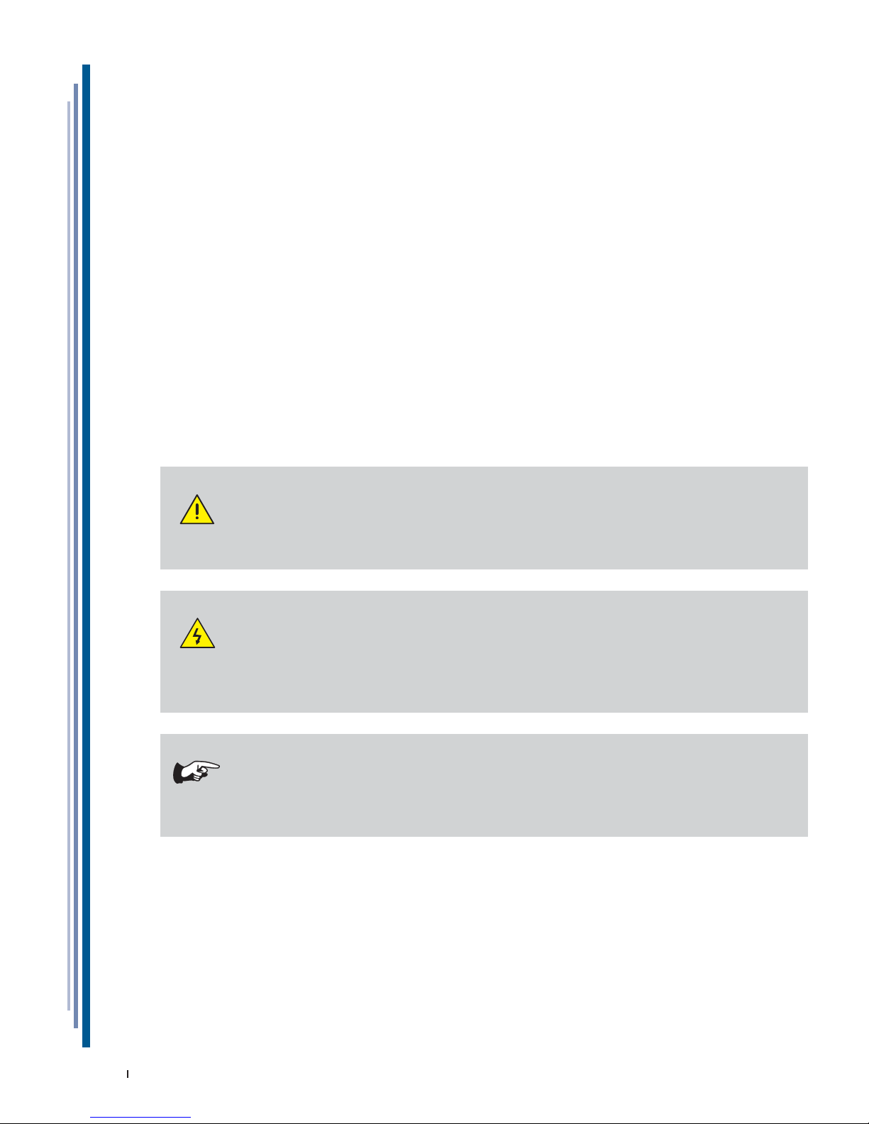
DANGER
Unauthorised tampering or replacement of one or more parts of the
appliance, use of accessories that modify the use of the same and use
of spare parts different to those recommended, can become the cause
of injury.
DANGER
Any work conducted on the on the appliance must involve
disconnection from the power socket and in any case, none of the
protective elements (grid, casing) should be removed by non-qualifi ed
staff.The appliance should not be operated when these protective
elements have been removed.
NOTE
In order not to compromise functionality and safety of the appliance,
the particularly complex installation and maintenance activities are
not documented in this manual and are performed by specialised ISA
technicians.
Never use electric devices inside this appliance. Do not use mechanical or
other means to accelerate the defrosting process, other than recommended by
the manufacturer. Keep the air vents in the casing of the appliance or in the
structure built into the wall free of obstructions. Do not damage the refrigerant
circuit.
RISK OF EXPLOSION
Do not store in the equipment products which contain fl ammable propellants
and explosives.
1. NOTES / WARNINGS
Page 6
6
USE AND MAINTENANCE MANUAL
EN
428000692237 MARIN
STAFF TRAINING
The buyer is responsible for ensuring personnel who will use the appliance
and maintenance technical staff are instructed and trained adequately. The
manufacturer is available for advice, clarifi cations, etc. so that the operator and
technical staff can use the appliance correctly.
To ensure the operator’s safety, appliance devices should be kept in constant
working order. This manual is intended to illustrate the use and maintenance of
the appliance. The operator has a responsibility and duty to carefully observe the
instructions contained within it.
Failure to comply with safety standards may result in injury to personnel and
damage to the equipment components and control unit. The user can contact
the dealer to request additional information not contained in this document, or
suggest improvements, at any time.
Before the product is delivered to the customer, it is essential that
a trained technical member of staff checks that the appliance is
operating correctly in order to achieve maximum performance.
INTRODUCTION
ISA employs materials of the best quality and as they enter the company,
we constantly monitor their storage and the use as part of the manufacturing
process to prevent damage, deterioration and failure. All manufacturing elements
are designed and manufactured in order to guarantee reliability and high safety
standards. All appliances are subjected to a strict testing procedure before delivery .
However, please bear in mind that product performance over time depends on
correct use and adequate maintenance. This manual contains the necessary
instructions to maintain the appliance’s initial appearance and functions over
time.
The Use and Maintenance manual contains the necessary information for
understanding how the appliance works and how to use it properly, namely:
the technical description of the various operational units, equipment and safety
systems, operations, how to use the instruments and the interpretation of
any diagnostics reports, main procedures and information relating to routine
maintenance. For correct use of the appliance, the working environment should
comply with current health and safety standards.
The safety requirements, indications, standards and notes illustrated in the
various chapters of the manual are aimed at establishing a code of conduct and
a series of obligations to be observed when performing the various activities, in
order to create safe conditions for personnel, the equipment and the surrounding
environment.
1. NOTES / WARNINGS
Page 7
7
USE AND MAINTENANCE MANUAL
EN
428000692237 MARIN
The safety standards reported in this document are intended for trained, authorised
personnel responsible for:
• Transport
• Installation
• Operation
• Management
• Maintenance
• Cleaning
• Putting out of order
• Disposal
ATTENTION
Reading this manual, albeit in full, is no substitute for adequate user
experience. therefore it should only be considered a useful reminder
of the technical features and the main operations to perform.
NOTE
The installers and users must read and understand
the instructions contained herein before any
operation on the appliance.
1. NOTES / WARNINGS
Page 8
8
USE AND MAINTENANCE MANUAL
EN
428000692237 MARIN
1. NOTES / WARNINGS
R744 - REFRIGERANT (WHERE APPLICABLE)
R744 The refrigerant R744 is a gas that is compatible with the environment.
Pay close attention during transport, installation and that the
destruction not to damage the refrigerant pipelines.
IN THE EVENT OF DAMAGE:
Keep away from the fl ame or ignition sources. Properly ventilate the premises
for a few minutes. Turn the unit off, pull the plug. Inform customer support
service.
WARNING
The refrigerant system is High Pressure.
Do not tamper with the system, but call a specialised and qualifi ed technician
before disassembly.
ATTENTION
Maintenance must be performed exclusively by qualifi ed staff.
R290 - REFRIGERANT (WHERE APPLICABLE)
The refrigerant R290 is a gas that is compatible with the environment,
but highly fl ammable.
Pay close attention during transport, installation and that the
destruction not to damage the refrigerant pipelines.
IN THE EVENT OF DAMAGE:
Keep fl ames or sources of ignition away from the appliance. Properly ventilate
the premises for a few minutes. Turn the unit off, pull the plug. Inform customer
support service. The more refrigerant containing an appliance, the greater must
be the environment in which there is the unit. In areas too small, in the event of
leakage can form a fl ammable mixture of air and gas. The volume of the room
where the appliance is installed must be at least 19 m³ for each cooling
system present in the room.
ATTENTION
Maintenance must be performed by qualifi ed personnel that has been
to work with fl ammable refrigerants.
Page 9
9
USE AND MAINTENANCE MANUAL
EN
428000692237 MARIN
1. NOTES / WARNINGS
R600a - REFRIGERANT (WHERE APPLICABLE)
The refrigerant R600a is a gas that is compatible with the
environment, but highly fl ammable.
Pay close attention during transport, installation and that the
destruction not to damage the refrigerant pipelines.
IN THE EVENT OF DAMAGE:
Keep fl ames or sources of ignition away from the appliance. Properly ventilate
the premises for a few minutes. Turn the unit off, pull the plug. Inform customer
support service. The more refrigerant containing an appliance, the greater must
be the environment in which there is the unit. In areas too small, in the event of
leakage can form a fl ammable mixture of air and gas. The volume of the room
where the appliance is installed must be at least 17 m³ for each cooling
system present in the room.
ATTENTION
Maintenance must be performed by qualifi ed personnel that has been
to work with fl ammable refrigerants.
Page 10
10
USE AND MAINTENANCE MANUAL
EN
428000692237 MARIN
2. MANUFACTURER
ISA
Bastia Umbra - Perugia - Italy
Tel. +39 075 80171
Fax +39 075 8000900
www.isaitaly.com
3. WARRANTY TERMS AND CONDITIONS
The seller’s warranty on the equipment is valid for 12 (TWELVE) months from the date of delivery.
The warranty includes repairs or replacements of any faulty parts due to manufacturing processes or installation after
written communication has been received, stating the appliance serial number and date of installation.
Not included in the warranty:
• All defects caused by incorrect use of the appliance.
• All defects caused by incorrect electrical connection.
• All defects caused by normal wear (for instance compressor failure and fl uorescent lamp malfunctioning that is not
due to manufacturing defects).
• Calls for installation, technical instructions, adjustments and cleaning the condenser.
If the seller’s technical staff detect any tampering, unauthorised repairs or inappropriate use of appliance the warranty
will be invalidated.
Shipment of components covered by the warranty is freight collect only.
Any damage to the appliance detected at the time of delivery due to transport must be reported on the same shipping
note to claim compensation from the carrier.
The seller cannot be held liable in the event of damage to the preserved product due to appliance failure.
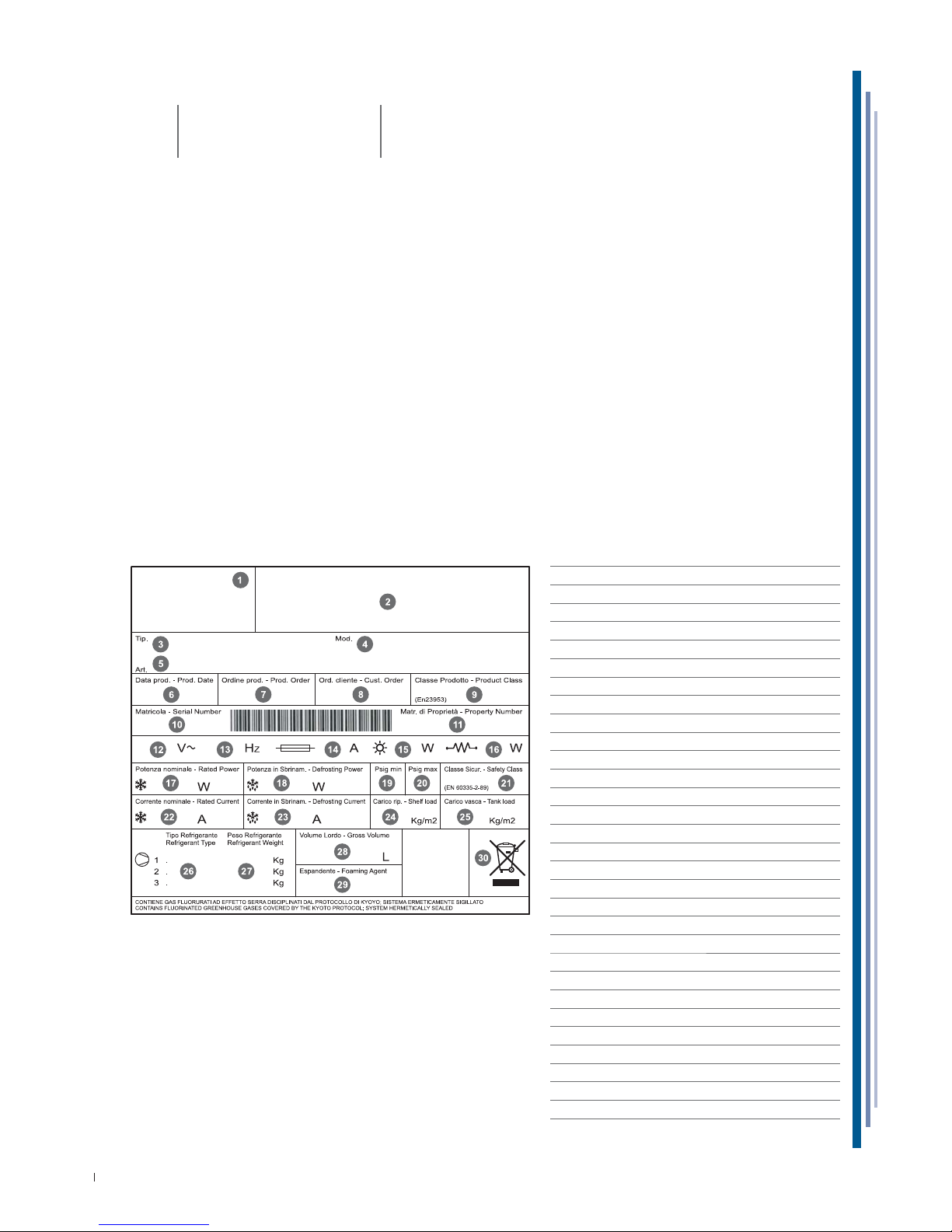
4. EQUIPMENT IDENTIFICATION
• Find the label affi xed on the machine to read the technical data.
• Check the machine model and the power supply voltage before you perform any operation.
• If you uncover mismatches, contact the manufacturer or the company that supplied the machine immediately.
1 IDENTIFICATION OF THE COMPANY PRODUCT MANAGER
2 SYMBOLS OF COMPLIANCE
3 TYPE
4 MODEL NAME
5 ARTICLE
6 PRODUCTION DATE
7 PRODUCTION ORDER
8 CUSTOMER ORDER
9 PRODUCT CLASS
10 SERIAL NUMBER
11 OWNER REGISTRATION NUMBER
12 VOLTAGE
13 SUPPLY VOLTAGE
14 FUSE VALUE
15 LAMP POWER
16 ELECTRICAL RESISTANCE ABSORPTION
17 NOMINAL POWER (NORMAL OPERATION)
18 POWER (DEFROSTING)
19 MINIMUM PRESSURE
20 MAXIMUM PRESSURE
21 SAFETY CLASS
22 NOMINAL CURRENT
23 CURRENT DURING DEFROSTING
24 LEVEL LOAD
25 TANK LOAD
26 TYPE OF COOLANT
27 WEIGHT OF COOLANT
28 GROSS VOLUME
29 EXPANDING ISOLATION AGENT
30 WEEE MARK
Page 11
11
USE AND MAINTENANCE MANUAL
EN
428000692237 MARIN
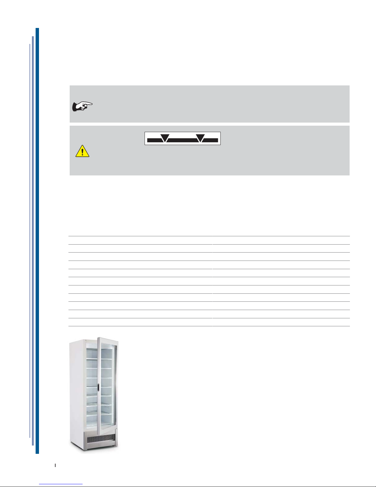
5. USE
This appliance is exclusively intended to:
DISPLAY AND SELL PRE-PACKED ICE CREAM
The manufacturer is not liable for injury to persons or damage to property or the appliance itself caused by the
displaying of products other than those described above.
THE APPLIANCE IS INTENDED FOR PROFESSIONAL USE
Uses not allowed
• Food preservation.
• Displaying and/or preserving non-food products (chemicals, pharmaceuticals, etc...).
ATTENTION
LOAD LIMITS
It is fundamental not to exceed the load limits indicated in order to avoid altering the correct circulation
of air and to avoid the temperature of the product being too high.
The limits indicated refer to a static and evenly distributed load. Therefore dynamic overloads due to
violent loading operations are excluded, which must be prevented foe safety reasons.
5.1 COMPOSITION
The appliance is made up from a unique cabinet, onto which all devices necessary to make it a professional and effi cient
product for its declared use, are installed.
The appliance is made up from:
Cooling system at Static Refrigeration (RV) RS
Cooling system at Ventilated Refrigeration RV
Condenser unit on board (UCA)
Electrical system
Electronic controller
Insulated monolithic structure in ecological polyurethane
Height-adjustable feet for stabilisation of the fl oor
One-way pads for handling and positioning
Lighting LED
Evaporating shelves fi xed RS
Adjustable shelves in height RV
Door with self-closing
Page 12
12
USE AND MAINTENANCE MANUAL
EN
428000692237 MARIN
6. SAFETY
The appliance is equipped with safety devices. The buyer is responsible for training personnel using the appliance on
the risks, safety devices and general health and safety rules required by the laws of the country where the appliance
is installed. Users/operators should be aware of the position of all the controls and how they work, as well as of the
features of the appliance. They must also have read this manual in its entirety.
6.1 SAFETY DEVICES PRESENT
Devices whose operation prevents the occurrence of risk situations in operating conditions (e.g. fuses, pressure
switches, protections, magnet circuit breakers, etc.).
6.2 FIXED PROTECTIONS
Fixed protective devices consist of fi xed perimeter shields, which are used to prevent external parts from entering the
equipment.
DANGER
It is prohibited to re-start the appliance following maintenance without having correctly restores the
panels.
VISUAL CHECK
You should check the integrity of fi xed panels and corresponding fi xings to the frame, focussing in
particular on the protective panels.
6.3 ISOLATING THE ELECTRIC POWER SUPPLY
Before conducting any maintenance work on the equipment or part of it, it is necessary to section the power supply that
powers it.
DANGER
In the event of maintenance operations in which the operator cannot prevent accidental closure of the
circuit by others, to totally disconnect the appliance from the mains electricity.
6.4 RESIDUAL RISKS
During design the manufacturer examined all the areas or parts at risk.Therefore, all necessary precautions have been
taken to prevent risks to persons and damage to the appliance.
ATTENTION
• Periodically check that all safety devices are operating correctly.
• Do not remove the fi xed guards.
• Do not introduce objects or tools into the work area.
Although the appliance is fi tted with the safety devices prepared, there are still some risks that cannot be eliminated,
but reduced via corrective actions by the fi nal integrator and correct operational procedures.
Below is a summary of the remaining risks associated with the appliance during:
• Normal operation.
• Adjustement and tweaking.
• Maintenance.
• Cleaning.
6.5 RISKS OF CONTACT WITH LIVE PARTS
Risk of breaking or damaging the electrical components of the appliance, with a possible reduction in safety levels,
following a short circuit.
Before connecting the electricity supply, make sure there is no ongoing maintenance work.
ATTENTION
Before making the connection, check that the d.c. current in the installation point does not exceed that
indicated on the protections switches present in the electric control board.If this is not the case, the user
must envision the relevant limiting devices. It is strictly forbidden to conduct any electrical modifi cation, in
order to prevent additional unforeseen hazards and risks.
6.6 FIRE
DANGER
In the event of a fi re, immediately disconnect the master switch from the main power supply line.
Page 13
13
USE AND MAINTENANCE MANUAL
EN
428000692237 MARIN
6.7 EXPLOSIVE ATMOSPHERE
The equipment must not be located in an area classifi ed as an explosion risk according to 1999/92/EC such as:
Zone 0
An area in which there is a permanent, long-lasting or frequently explosive atmosphere made up of a mixture of air and
fl ammable substances in the form of gases, fumes or steam.
Zone 1
An area in which the formation of an explosive atmosphere, made up of a mixture of air and fl ammable substances in
the form of gases, fumes or steam is occasionally probable during normal activities.
Zone 20
An area in which there is a permanent, long-lasting or frequently explosive atmosphere in the form of clouds of
combustible dust in the air.
Zone 21
An area in which the formation of an explosive atmosphere in the form of clouds of combustible dust is occasionally
probable during normal activities.
6.8 SLIPPING
DANGER
Any leaks in the areas surrounding the appliance may cause personnel to slip. Check that there are
no leaks and keep these areas clean at all times.
6.9 TRIPPING
DANGER
Generally untidy deposits of material may constitute a tripping hazard and a total or partial
obstruction of emergency exit routes. You should ensure that operating and transit areas and escape
routes are free from obstacles in compliance with current law.
6.10 CIRCUIT FAULTS
Owing to potential faults, safety circuits may become less effective, which results in lower safety levels. You should
check the operational condition of the appliance devices regularly.
6.11 WARNING SIGNS (IF ANY)
The appliance is fi tted with warning danger, warning and obligation signs defi ned in agreement with the Standard relative to
the graphical signs to be used on plants. The signs are located in clearly visible positions.
ATTENTION
The warning plates present on the appliance must not be removed.
The user is responsible for replacing warning signs that, owing to wear, become unreadable.
6.12 FALLING OBJECTS
Positioning of the cabinet display parts (i.e. counters, rods and hooks), as also product arrangement inside the cabinet
can be the source of potential hazards if not properly performed. Follow the positioning instructions described in this
Manual before you place products inside the cabinet, check that the counters are properly fastened, as also the hooks,
etc. Do not exceed the maximum load limit. Do not exceed the maximum load limit. Do not position tilted product on
the counters if they are not held in place by their stoppers.
6.13 COOLING
During different operations to perform on the counter, such as cleaning or loading goods, it is necessary to handle
products and/or counter parts at a low temperature with the risk of “cold injury” for the operators and/or accidental
slipping hazard. Follow the safety regulations in the place where the cabinet is installed; more specifi cally, be sure to
always use the right PPE (especially gloves).
6.14 FOODSTUFFS SAFETY (PACKAGED PRODUCTS)
The refrigerator cabinet described herein is meant to be used to display packaged products. As such, it is not designed
for direct contact between the foodstuffs and display surfaces. If the foodstuffs do accidentally make contact with
the surfaces and for a rather long time, the product may be contaminated. Follow the guidelines on how to use the
cabinet. If a product package breaks, remove it from the cabinet and clean, if necessary.
Page 14
14
USE AND MAINTENANCE MANUAL
EN
428000692237 MARIN
7. DISPOSAL OF WASTE MATERIAL
During normal operation, the appliance does not generate any environmental contamination. At the end of its life cycle,
or if it is necessary to proceed to permanent decommissioning, we recommend following the procedures below:
DISPOSAL (USER)
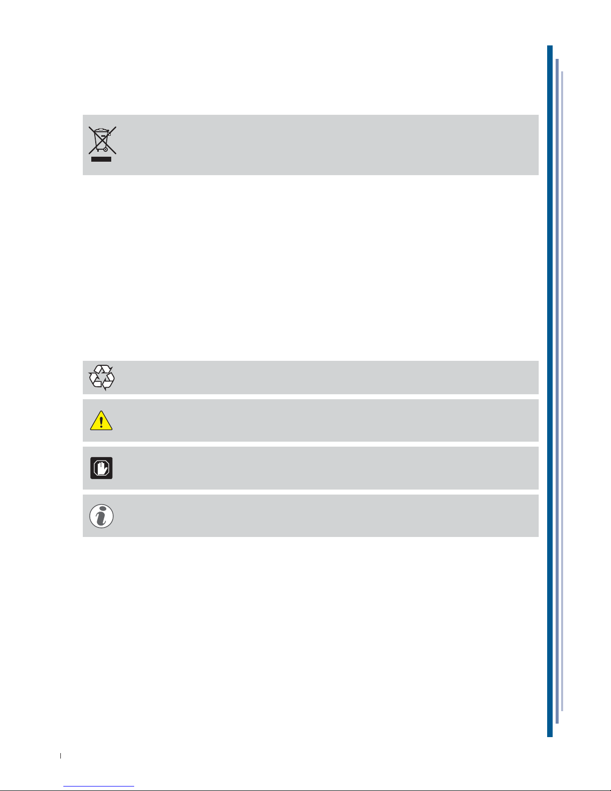
The symbol, applied to either the product or its packaging, indicates that the product should not be
considered as normal domestic waste, but should be taken to a waste collection point for the recycling
of electrical and electronic appliances. The correct disposal of this product contributes to preventing
potential negative consequences that might derive from an inadequate disposal of the product. For detailed
information about recycling this product, contact your council, your local waste collection service or the
store where you purchased the product.
PROCEDURE FOR DISPOSAL and RECYCLING AT THE END OF APPLIANCE LIFE SPAN
(AUTHORISED BODIES)
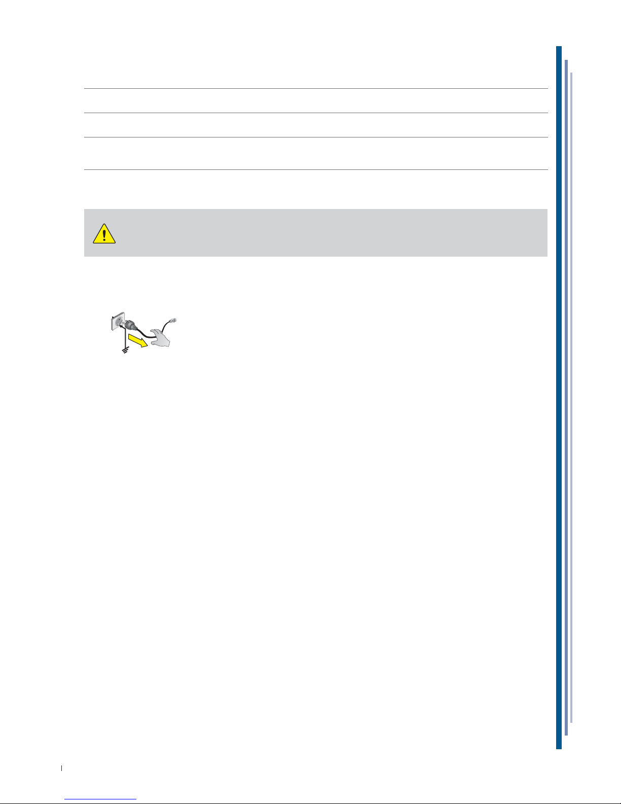
• Switch off the equipment and unplug the power supply cable.
• Remove the lamps (if installed).These should be disposed of separately.
• Remove the power units and the electronic cards.These should be disposed of separately.
• Remove all the independent parts (grids, casings, profi les, etc.) and group them according to shared features in
order to access the heat exchangers, pipes, cables, etc. and be careful not to damage the cooling circuit.
• Remove all mobile parts (doors, sliding doors, glass parts, etc.) and group the various materials according to their
features.
• Check the type of refrigerant on the plate positioned inside the counter; extract the refrigerant and dispose of it
through authorised services.
• Disconnect the evaporator, condenser, compressor, pipes and fans. These are made of copper, aluminium, steel and
plastic and should therefore disposed of separately.
• On removal of all guards and the various components from the frame, separate the different types of material
making up the appliance (plastic, sheet steel, polyurethane, copper, etc) and collect them separately.
All recyclable materials and waste should be processed and recycled by professionals, in compliance
with the laws in the country in question. The company responsible for recycling the materials should be
registered and certifi ed as a waste disposal service in accordance with the country in question.
ATTENTION
Illegal disposal of the product by the owner will result in administrative sanctions as required by current
laws. Disposal of the product should comply with current laws on the disposal of coolant liquids and mineral
oils.
IMPORTANT
If the crossed wheelie bin sign is not present on the appliance, it means that the disposal of the product is
not the manufacturer’s responsibility. In this case, the Regulations regarding the disposal of waste in force
are valid.
ADDITIONAL INFORMATION
Further information on the disposal of liquid coolant, oils and other substances is available on the safety
data sheet corresponding to the substance itself. In order to dispose of foamed assemblies, remember that
the polyurethane foams used are CFC, HFC and HCFC free.
Page 15
15
USE AND MAINTENANCE MANUAL
EN
428000692237 MARIN
8. INSTALLATION
This manual supplies the information necessary for correct unpacking, procedures for positioning and connection to
mains electricity.
8.1 STORAGE AND UNPACKING
The appliance, with or without the packaging, should be carefully stored inside warehouses or in areas away from the
elements and direct sunlight, at a temperature between 0 and +40 °C.
The movement of the apparatus should only be carried out using a fork lift of a suitable power for
the weight of the same and manoeuvred by qualifi ed personnel: during such operations
the equipment must be positioned on the supplied pallet.
Unplug the appliance from removing the screws that lock the pallet.
All packaging materials are recyclable and should be disposed of in accordance with local regulations.
Please destroy “plastic” bags to prevent them from becoming hazardous to children (suffocation).
8.2 ENVIRONMENTAL CONDITIONS
ATTENTION
A dry room that can be ventilated is the suitable location for the appliance’s installation. There should be
a good air fl ow around the compressor/condensing unit.Therefore the area around the unit should not be
obstructed by boxes or other objects.
Place the equipment away from sources of heat (radiators, heaters of any kind, etc.) and far from the
infl uence of continuous air movement (caused by fans, air conditioning units, etc.). If it is unavoidable to
install near a heat source, use a suitable insulating plate,
Also avoid exposure to direct sunlight; all of this causes the temperature inside the refrigerated
compartment to rise with negative consequences on operation and energy consumption. Do not use the
appliance outdoors and do not leave it exposed to rain.
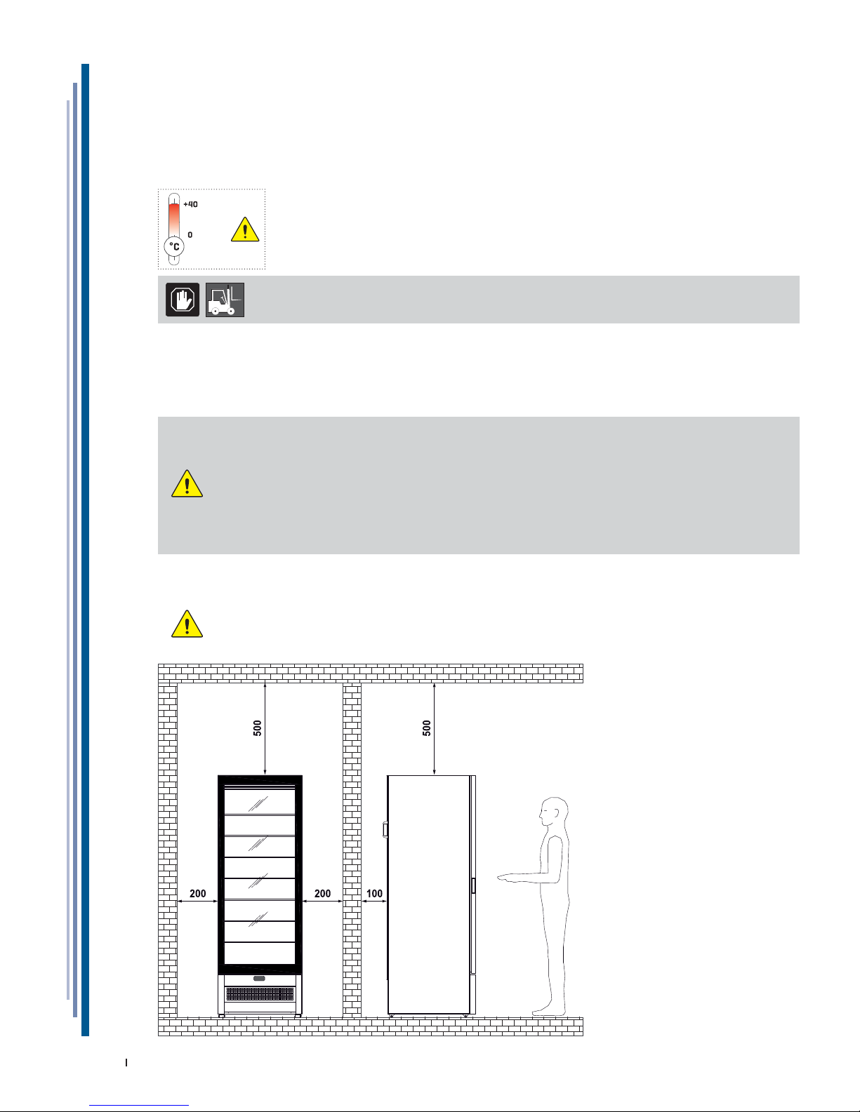
8.3 INSTALLATION
ATTENTION
It is fundamental to respect the distances indicated (mm) for correct installation of the appliance.
MAX
MIN
Page 16
16
USE AND MAINTENANCE MANUAL
EN
428000692237 MARIN
8.5 ELECTRIC CONNECTION
ATTENTION
Check that the network voltage matches the one displayed on the identifi cation plate of the appliance,
and that the power is adequate. Check on the socket that the power supply voltage provides rated voltage
(±10%) when you start up the compressor. The plug should be directly connected to the electrical socket.It
is forbidden to connect the plug to the socket by means of multiple socket extensions or adaptors.
the plant power supply socket must be fi tted with a disconnection device from the mains electricity
(dimensioned to the load and in compliance with Standards in force), which guarantees complete
disconnection in category III (3) over-voltage conditions and therefore protects the circuits against earth
faults, overloads and short circuits. Do not route the electricity cable in passageways.
ATTENTION
Earthing is necessary and mandatory by law.
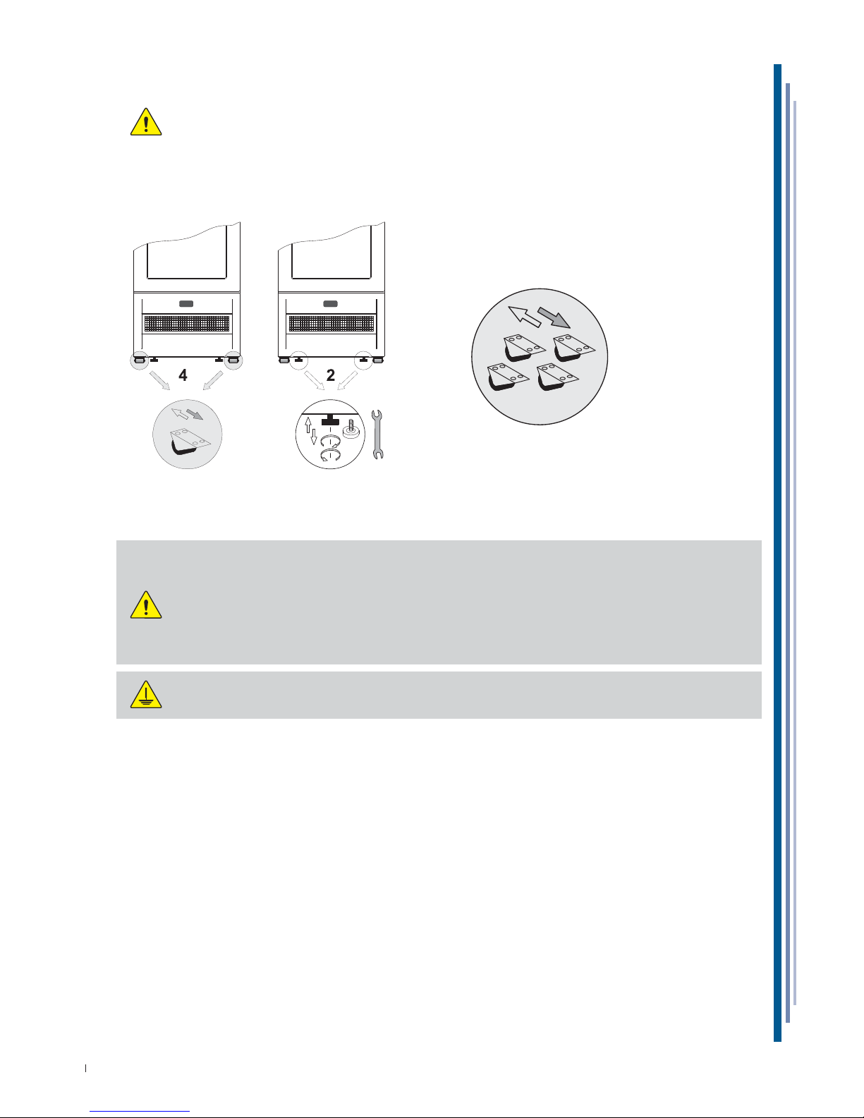
8.4 POSITIONING
ATTENTION
ONE-WAY PADS
The appliance is set-up with four (4) one-way pads for handling and positioning.
HEIGHT-ADJUSTABLE FEET
The appliance is set-up with two (2) height-adjustable feet for stabilisation of the fl oor.
After positioning it is necessary to stabilise the appliance to the ground.
Page 17
17
USE AND MAINTENANCE MANUAL
EN
428000692237 MARIN
9. MAINTENANCE
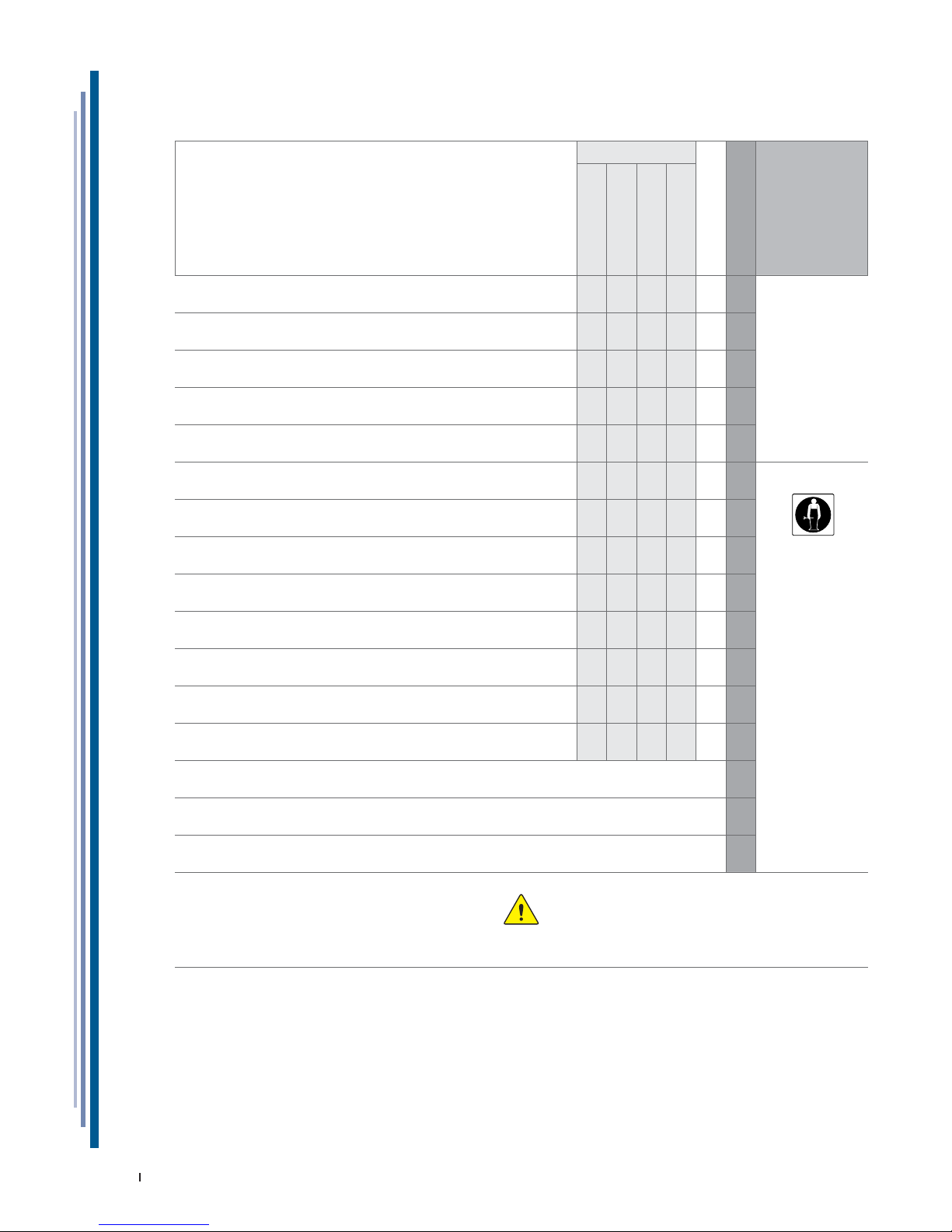
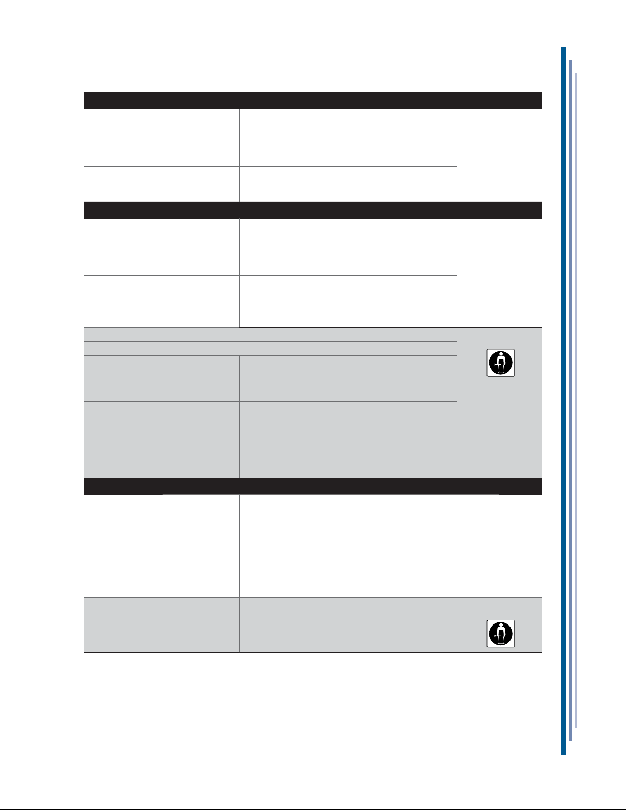
The Staff in charge of the appliance must control and respect the expiry dates for maintenance, given in the table
below, calling the authorised Technical After-sales assistance when indicated.
OPERATION FREQUENCY
ORDINARY
EXTRAORDINARY
PERSONNEL
AUTHORISED
Depending on the
Use and Necessity
Monthly
six-month
Annual
CLEANING THE EXTERNAL SURFACES
XX
USER
CLEANING THE ACCESSIBLE INTERNAL PARTS
(without the use of tools)
XX
CONTROL POWER SUPPLY CABLE,
PLUGS AND / OR ELECTRICAL SOCKETS
XX
INTEGRITY CONTROL SEAL
XX
FILTER CLEANING CONDENSING UNIT
(whenever present)
XX
CLEANING THE DEFROSTING WATER COLLECTION TRAY
XX
TECHNICAL
ASSISTANCE
CONDENSER CLEANING
XXX
CHECK COMPRESSORE OIL LEVEL
(whenever present)
X
AIR TANK DRAINING
(whenever present)
XX
CONTROL PNEUMATIC CONNECTIONS
(whenever present)
XX
INTEGRITY CONTROL PIPE COOLING SYSTEM
XX
INSPECTION OF CABLES
INTERNAL CONNECTIONS AND POWER
XX
CLEANING CONDENSATE DRYING SPONGES
(whenever present)
XX
LAMP / LED REPLACEMENT
(whenever present)
X
CONTROL PANEL REPLACING
(electronic control unit - thermostat - etc)
X
REPLACEMENT POWER SUPPLY CABLE, PLUGS AND / OR ELECTRICAL SOCKETS
X
ATTENTION
After all maintenance it is mandatory to perform all electric safety tests in agreement
with the IEC EN 50106 Standard.
Page 18
18
USE AND MAINTENANCE MANUAL
EN
428000692237 MARIN
10. FAULTS - TECHNICAL AFTER-SALES ASSISTANCE
If the appliance is not working properly or stops working, before contacting the Customer support centre,
check the following
:
THE EQUIPMENT DOES NOT WORK
CAUSE SOLUTION
PERSONNEL
AUTHORISED
Blown protective fuse Find the cause of the intervention of the switch fi rst, and then
replace the new fuse.
USER
The master switch is open Close the master switch.
The plug is not inserted Insert the plug.
Electrical black-out If the black-out should be prolonged, transfer the product
into an appropriate cold storage container.
THE INTERNAL TEMPERATURE IS NOT LOW ENOUGH
CAUSE SOLUTION
PERSONNEL
AUTHORISED
Evaporator/s obstructed completely
by ice
Carry out an additional defrosting cycle. USER
Wrong temperature setting Set the appropriate temperature.
The appliance is affected by draughts or is
exposed to direct or refl ected sunlight
Remove any draughts and prevent any direct or refl ected
sunlight.
Insuffi cient air fl ow for
cooling to the condenser
Remove anything that may affect air fl ow inside the condens-
ing unit (paper sheets, cardboard, grids with an insuffi cient
number of holes, etc.).
Internal fans at standstill or with fans damage TECHNICAL
ASSISTANCE
Internal ventilation is too high
Thermostat / Electrical base unit
not effi cient
Replace the electronic control board.
If the control unit is set up especially for must R290 refrigerant, it must only be replaced with an original replacement
from ISA. Replace the temperature probes only after
checking which of the two is not operating effi ciently.
Condenser unit blocked by dust
or dirt in general.
Clean the condensing unit thoroughly.
The air condenser or MAINTENANCE FREE, in particular heavy
environments (e.g. presence of dust, the presence of excessive moisture, oiled vapours etc..) in order to avoid performance loss, needs accurate cleaning.
Insuffi cient refrigerant
load in the cooling system
Find the cause behind the lower amounts of coolant and
eliminate it.Top up the coolant.If necessary, empty the system before topping up.
THE COMPRESSOR DOES NOT START-UP OR OPERATES FOR A FEW MOMENTS
CAUSE SOLUTION
PERSONNEL
AUTHORISED
No electric power supply to the appliance Check if there is a power cut.
Close the various switches on the power supply line.
USER
Excessively low power voltage Check that the network voltage of the power supply cable is
220V +/- 10%.
Temperature set too high If the temperature is higher than the air temperature
in the display chamber, the compressor will not start.
Set the suited temperature if the current temperature
is not low enough.
Intervention of the maximum pressure
switch (where present)
Check the cause of continuous intervention of the maximum
pressure switch, which may be: air condenser blocked, condensing fan stopped, ambient
temperature too high, pressure switch defective.
TECHNICAL
ASSISTANCE
Page 19
19
USE AND MAINTENANCE MANUAL
EN
428000692237 MARIN
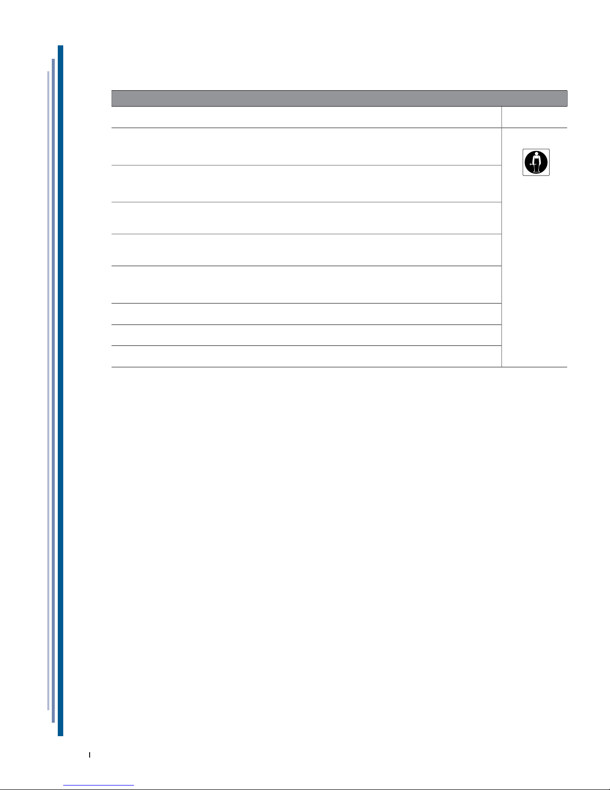
10.1 ALARMS LIST (IF PRESENT)
ALARMS
ALARM DESCRIPTION OUTPUTS
PERSONNEL
AUTHORISED
P1
E0
Broken thermostat probe.
Compressor output according to “COn” and
“COF parameters
• The alarm starts a few seconds after the probe breaks down; it
stops a few seconds after the probe starts working again properly.
• We recommend checking the probe connections before replacing it.
TECHNICAL
ASSISTANCE
P2
E1
Broken evaporator probe.
Set time for defrosting.
• The alarm starts a few seconds after the probe breaks down; it
stops a few seconds after the probe starts working again properly.
• We recommend checking the probe connections before replacing it.
HA
HI
High temperature alarm. • The alarm stops automatically on reaching the temperature set.
• Check programming.
LA
LO
Low temperature alarm. • The alarm stops automatically on reaching the temperature set.
• Check programming.
EA
IA
CB
External alarm. • The external alarm stops after the digital infeed is deactivated, it is
restored automatically.
• The alarm is linked to the intervention of the pressure switch and/or
the compressor circuit breaker, when present.
ETc
RTF
Real time clock is broken. • Reset the clock.
• If the alarm does not stop, replace the clock.
EE Machine parameter error. • The instrument is damaged. It must be replaced.
EF Operating parameters er-
ror.
• The instrument is damaged. It must be replaced.
Page 20
20
USE AND MAINTENANCE MANUAL
EN
428000692237 MARIN
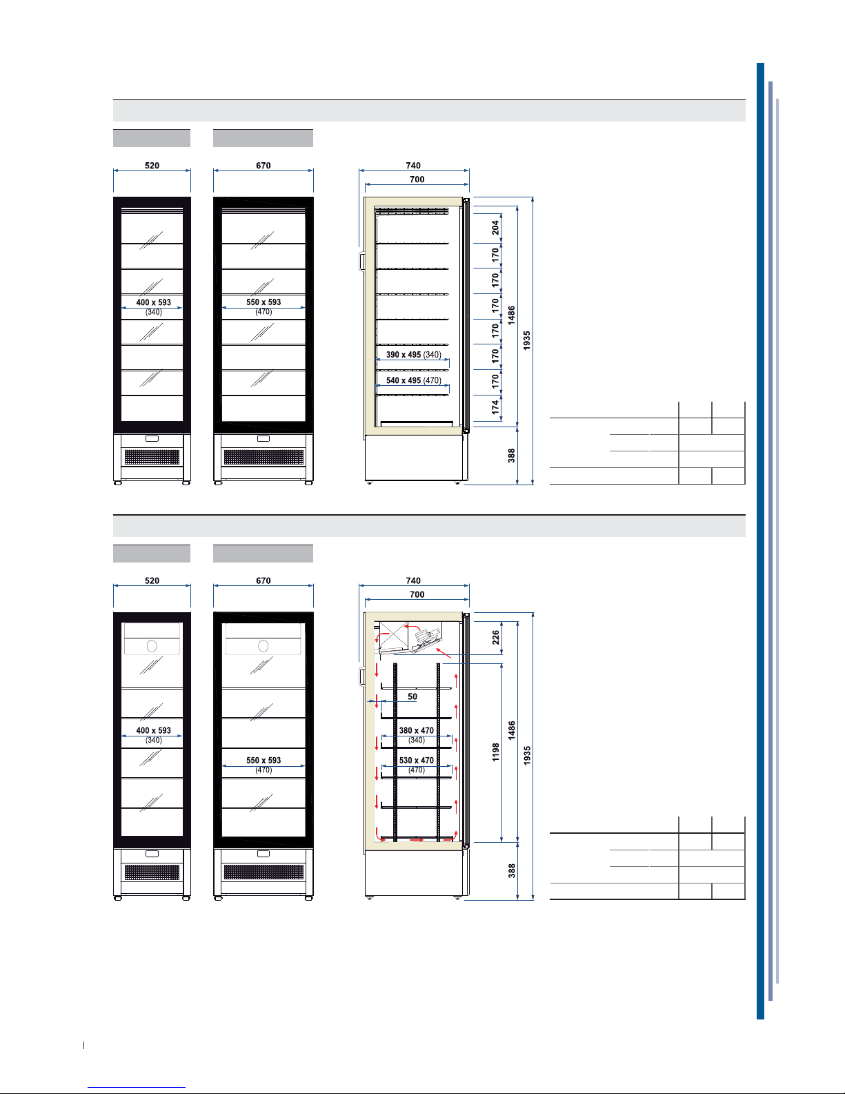
11. TECHNICAL SPECIFICATIONS
340 470
External
dimensions
Lenght mm 520 670
Depth mm 740
Height mm 1935
Weight (net) Kg 108 128
RS
340 470
RV
340 470
340 470
External
dimensions
Lenght mm 520 670
Depth mm 740
Height mm 1935
Weight (net) Kg 108 128
Page 21
21
USE AND MAINTENANCE MANUAL
EN
428000692237 MARIN
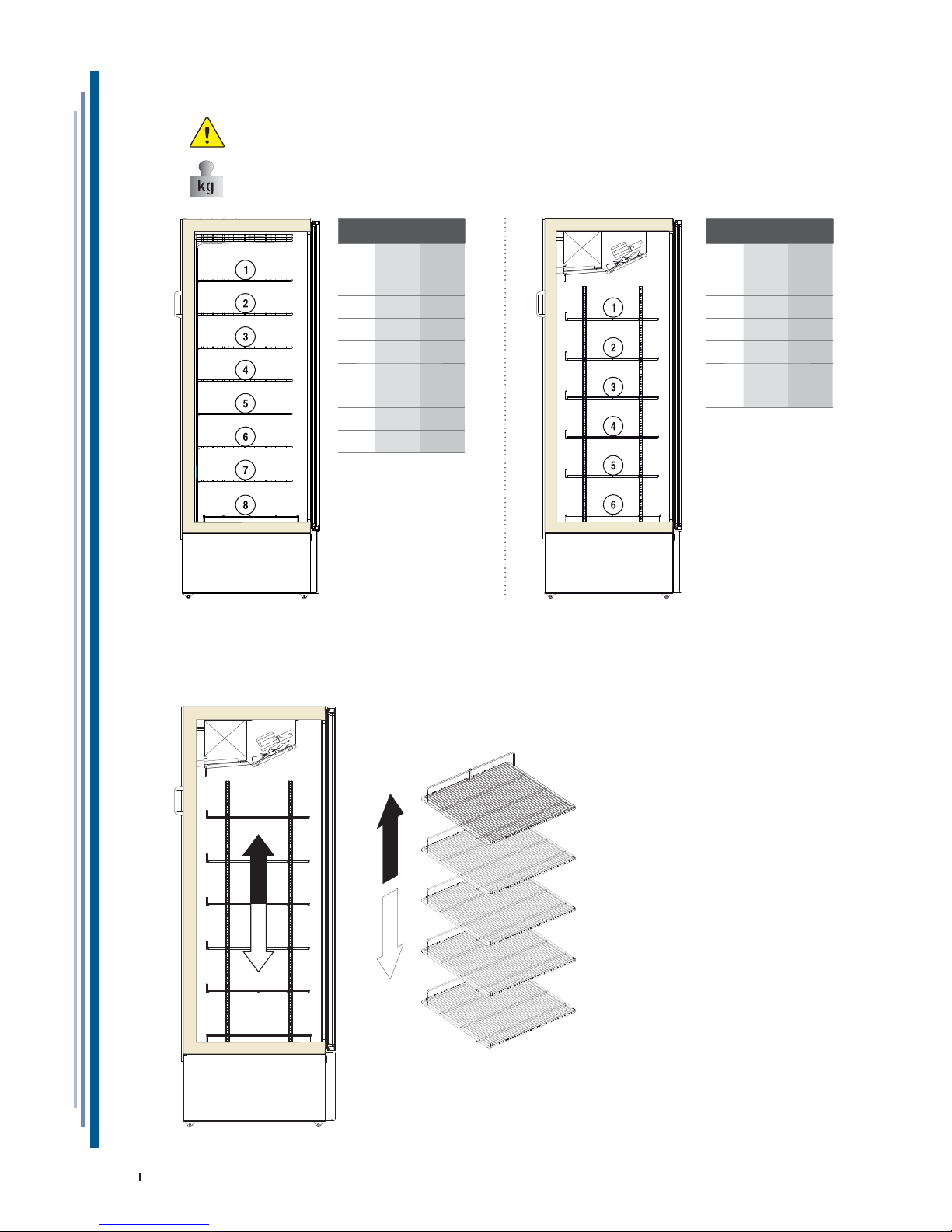
11.1 MAX LOAD ON SHELVES / GRIDS
ATTENTION
The load limits indicated for each shelf / grid must be respected to avoid their deformation or breaking.
RS
N° 340 470
12025
22025
32025
42025
52025
62025
72025
82025
RV
N° 340 470
12025
22025
32025
42025
52025
62025
11.2 GRIDS (RV)
The grids are adjustable in height as shown in fi gure.
Page 22
22
USE AND MAINTENANCE MANUAL
EN
428000692237 MARIN
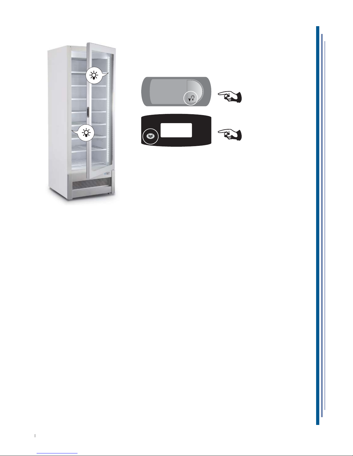
11.3 LIGHTING
ON/OFF
ON/OFF
Page 23
23
USE AND MAINTENANCE MANUAL
EN
428000692237 MARIN
12. CONTROL PANEL
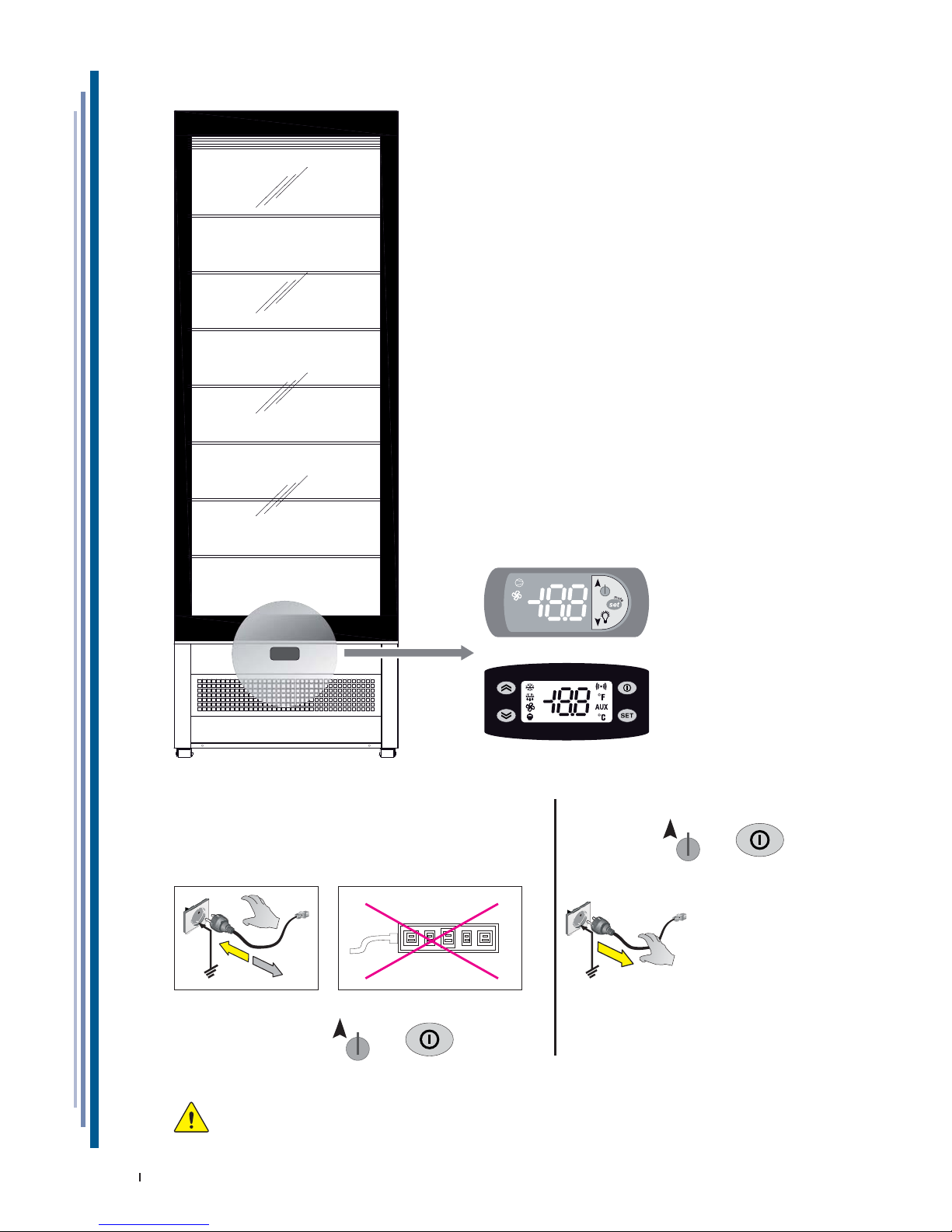
START-UP
Plug the appliance in at the socket supplied by the customer,
ensuring that the plug is fi tted with an earth contact and that
there are no multiple sockets connected to it.
The appliance will start working automatically
otherwise press the keys or .
NO
OFF
Press the keys or ;
otherwise detach the power plug.
WARNING
The electronic control board is installed already programmed.
Any changes to the control board settings can be carried out exclusively by qualifi ed technical personnel.
Page 24
24
USE AND MAINTENANCE MANUAL
EN
428000692237 MARIN
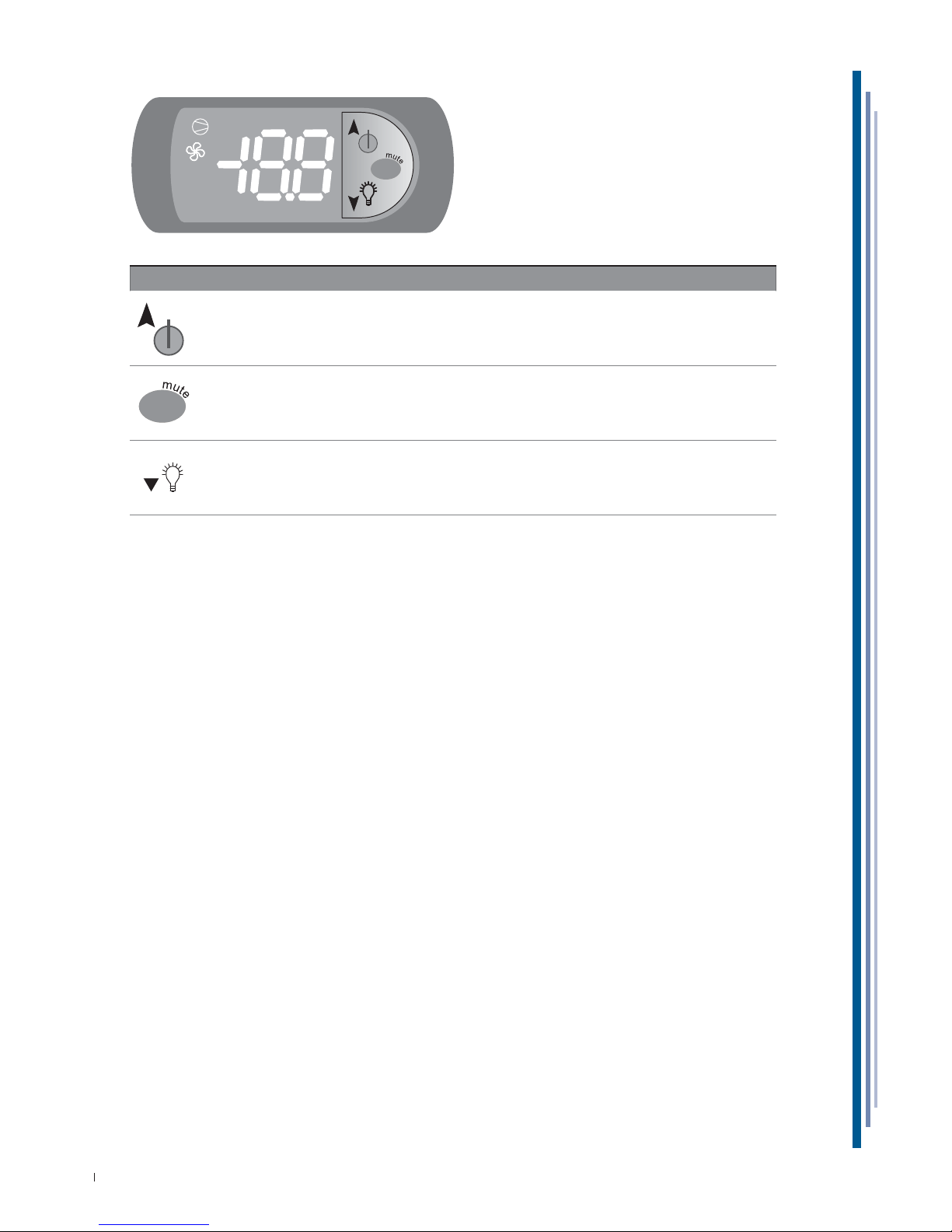
12.1 USER INTERFACE PJ EASY
set
KEYS
Pressed for more than 3 seconds alternates ON / OFF status
Pressed for 1 second displays/sets the set point.
Pressed for more than 3 seconds accesses the parameter setting menu (insert password 22).
Silences acoustic alarm (buzzer).
Lighting.
set
Page 25
25
USE AND MAINTENANCE MANUAL
EN
428000692237 MARIN
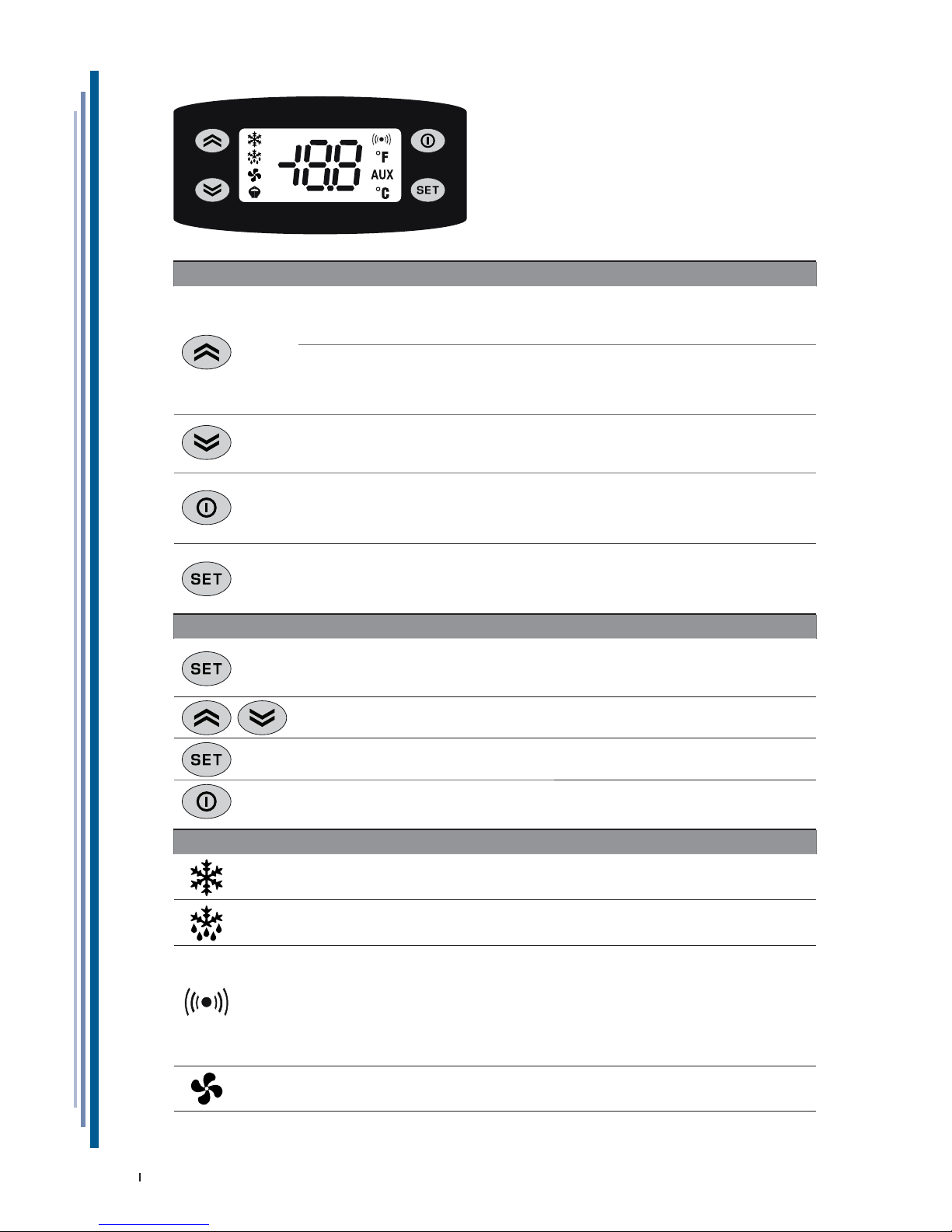
KEYS
UP
Scrolls menu options.
Increases the values.
Activates manual defrosting.
MANUAL ACTIVATION OF THE DEFROSTING CYCLE
To manually activate the defrosting cycle, press and hold the UP key for 5 seconds.
If defrosting conditions are not present (for instance the temperature of the evaporator probe is
higher than the temperature at the end of the defrosting process), the display will fl ash three (3)
times to indicate that the operation will not be performed.
DOWN
Scrolls menu options.
Decreases the values.
ON / OFF the internal lighting
STAND-BY (ESC)
Goes back up one level with respect to current menu.
Confi rms parameter value.
Activates the Stand-by function.
ON / OFF the equipment.
SET (ENTER)
Accesses the Set-point.
Accesses the programming menu.
Confi rm the commands.
Display any alarms (if present)
SETTING THE SET POINT
Press the SET (ENTER) button and release immediately.
The “Set” label will appear.
To view the Set point value, press the SET (ENTER) button again.
The Set-point value will appear on the display.
To change the Set point value, press the UP and DOWN buttons within 15 seconds.
To confi rm the new Set-point value set, press the SET (ENTER) key again.
By not operating on the keyboard for more than 15 seconds (time-out) or pressing the STAND-BY
(ESC) key once, the last value displayed is confi rmed and you go back to the previous display.
LED
COMPRESSOR or RELAY 1
ON for compressor on.
Flashing for delay, protection or blocked activation.
DEFROSTING
ON for defrosting in progress.
Flashing for manual activation.
ALARM
ON for active alarm.
Flashing for silenced alarm.
Alarm conditions are always signalled by the buzzer (if present)
and by the corresponding alarm icon LED.
The alarm signal deriving from a faulty probe (probe 1) appears
directly on the instrument display with the indication E1.
The alarm signal deriving from a faulty evaporator probe (probe 2)
appears directly on the instrument display with the indication E2.
FANS
ON for operating fans.
12.2 USER INTERFACE EW978
Page 26
26
USE AND MAINTENANCE MANUAL
EN
428000692237 MARIN
The materials listed below must be cleaned as follows:
STAINLESS STEEL Only use warm water and non-aggressive detergents and then rinse and dry
using a soft cloth.
ACRYLIC OR POLYCARBONATE Wash with lukewarm water, using a soft cloth or a chamois cloth.
Do not use abrasive cloths or sponges.
GLASS Only use products specifi cally designed for cleaning glass.
We do not recommend using tap water, which may leave calcium deposits on the
surface of the glass.
13. CLEANING
13.1 INTERNAL
ATTENTION
Do not scrape the ice from the walls with pointed tools, the surfaces will be ruined.
Do no use high pressure appliances (e.g. steam generators).
1. Remove the product contained in the refrigerated compartment and place it immediately in a special refrigerator
conservative to ensure proper storage.
2. Turn off the equipment.
3. Remove accessories manually removable (e.g.. Sliding, grills, ice cream containers, etc).
4. Wait at least 4 to 6 hours, until the ice on the evaporator has melted completely, before proceeding with cleaning
operations. We suggest in this regard, you wait for the next day to make sure that the defrosting is completely
done. Do not use mechanical devices or other means to accelerate the defrosting process, other than those
recommended by the manufacturer.
5. Remove (if present) the drain plug of the tank bottom to drain the defrost water.
6. Clean the side panels and the bottom of the tank using a mild detergent, warm water and a cloth or sponge. Do
not use sharp tools. Rinse thoroughly and dry with an absorbent cloth.
7. If the equipment was joined to a fl oor drain, slide lukewarm water containing a sanitizing solution suited to the
specifi c application. The amount of solution to be used should be such as to ensure a perfect removal of any
residual product and proper sanitation along the entire path of the drainage.
8. If the equipment is not joined to a fl oor drain, follow the procedure referred to above. The rinse water collected
in the tank will be positioned inside the base of the apparatus. Clean and disinfect the collection tray.
9. Fit the accessories that were removed (step 3).
10. Turn on the equipment and allow to cool on the bench until it reaches the desired temperature before
reintroducing foods.
Page 27
27
USE AND MAINTENANCE MANUAL
EN
428000692237 MARIN
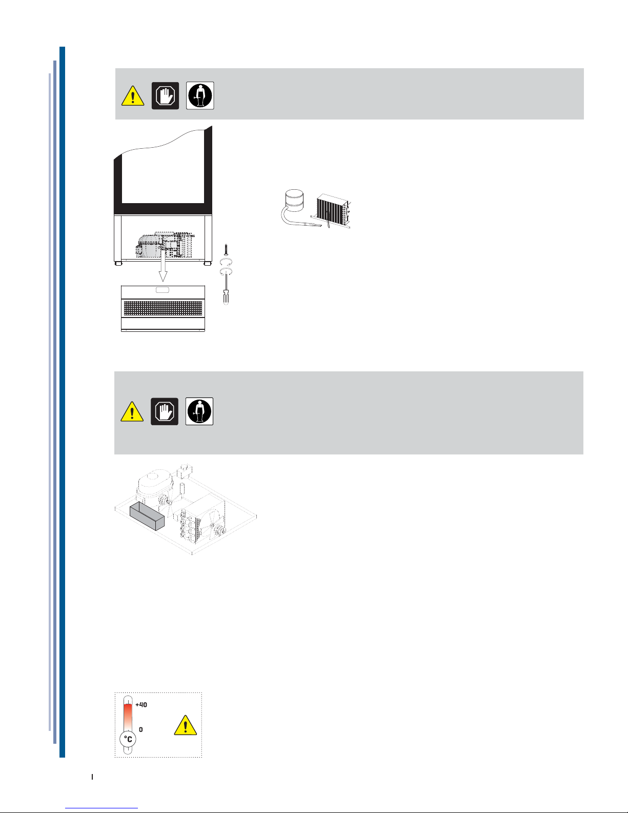
13.2 CONDENSING UNIT
ATTENTION
Turn off the product, wait a few hours until the equipment of the condensing unit has
reached a temperature close to that of the environment.
Remove the rear protective grids and front and remove them as shown.
Clean the condensing unit using a suction brush.Clean the condenser with
a soft bristle brush; make sure you do not bend the condensing unit
springs whilst cleaning it.
13.3 DEFROST WATER COLLECTION TRAY (IF PRESENT)
ATTENTION
Clean based on use and as needed and in certain environmental conditions (e.g., high
humidity, low environmental temperature, presence of dust, etc.) in order to avoid the
incorrect and complete evaporation of the water and/or the presence of unpleasant
odours.
Sanitise the tray with specifi c products.
14. PROLONGED APPLIANCE SWITCH-OFF
• Remove the product contained in the refrigerated compartment and place it immediately in a special refrigerator
conservative to ensure proper storage.
• Open the equipment and wait for it to reach room temperature and then clean it.
• Leave the door/sliding panels open by 2-3 cm so as to guarantee circulation of the air and prevent the formation of
mould and bad smells inside the appliance.
• The appliance, with or without the packaging, should be carefully stored inside warehouses or in areas away from
the elements and direct sunlight, at a temperature between 0 and +40 °C.
MAX
MIN
Page 28
ATTACHMENTS
28
USE AND MAINTENANCE MANUAL
EN
428000692237 MARIN
1
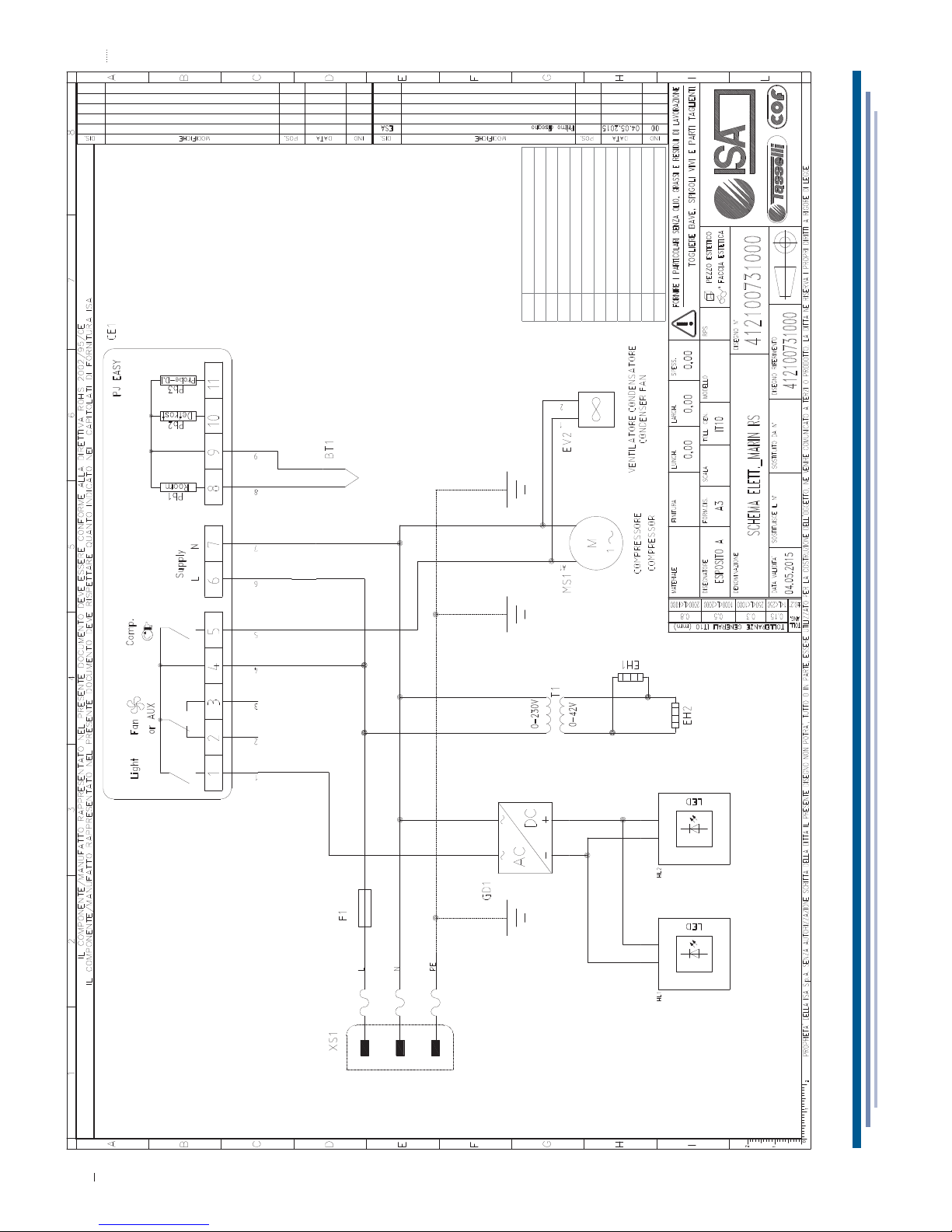
WIRING DIAGRAM - 412100731000
BT1 Temperature probe
CE1 Electronic control board
EH1 Heating Elements door glass
EH2 Heating Elements door perimeter
F1 Fuse
EV2 Condenser fan
GD1 Power supply led
HL1 Vertical led right
HL2 Vertical led left
MS1 Compressor
T1 Trasformer
XS1 Power supply
Page 29
ATTACHMENTS
29
USE AND MAINTENANCE MANUAL
EN
428000692237 MARIN
2
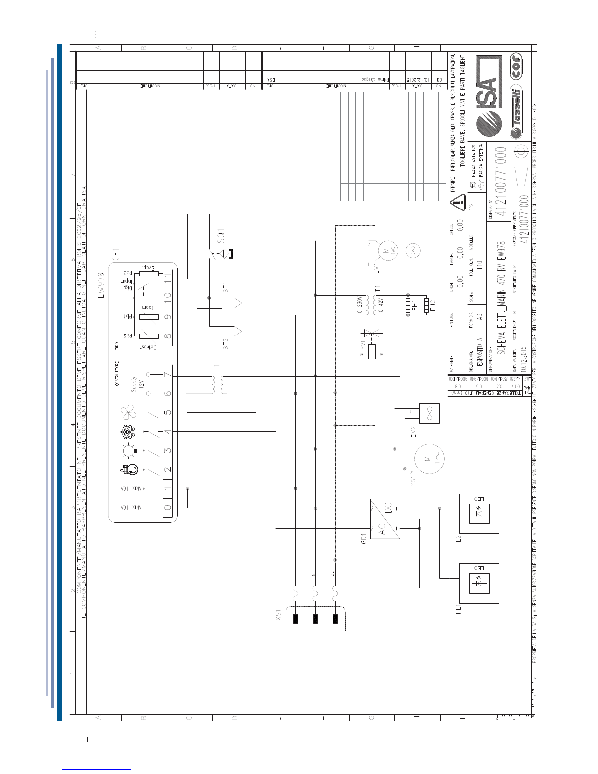
WIRING DIAGRAM - 412100771000
BT1 Temperature probe
BT2 Defrost probe
CE1 Electronic control board
EH1 Heating Elements door glass
EH2 Heating Elements door perimeter
EV2 Condenser fan
GD1 Power supply led
HL1 Vertical led right
HL2 Vertical led left
MS1 Compressor
SQ1 Door microswitch
YV1 Defrost valve
T1 Trasformer
XS1 Power supply
Page 30
ISA
Bastia Umbra - Perugia
Italy
Tel. +39 075 80171
Fax +39 075 8000900
www.isaitaly.com
 Loading...