

Marilyn DAR-01 User Manual
DAR-01 Rev. D
User’s Manual
Release Date 03/31/2015


Table Of Contents
Table of Contents
Introduction ........................................................................................................................................ 1
Disclaimer.............................................................................................................................................................................. 1
Warranty................................................................................................................................................................................ 1
Use and Care ....................................................................................................................................................................... 1
Contact Information ........................................................................................................................................................... 1
Overview ............................................................................................................................................. 2
Device Layout ...................................................................................................................................... 3
Front Panel ............................................................................................................................................................................ 3
Left Panel .............................................................................................................................................................................. 4
Right Panel ............................................................................................................................................................................ 5
Wiring Examples .................................................................................................................................. 6
Power ..................................................................................................................................................................................... 6
Speakers-stereo ................................................................................................................................................................... 7
Speakers-mono .................................................................................................................................................................... 7
Inputs with negative common .......................................................................................................................................... 8
Inputs with positive common ............................................................................................................................................. 8
Outputs with negative common ....................................................................................................................................... 9
Outputs with positive common ......................................................................................................................................... 9
Serial to PC.......................................................................................................................................................................... 10
Serial to Other Marilyn Systems Equipment ................................................................................................................... 10
File Names ........................................................................................................................................ 11
Configuration File ............................................................................................................................... 12
INI file overview .................................................................................................................................................................. 12
[StartUp] Section ................................................................................................................................................................ 13
[Audio] Section .................................................................................................................................................................. 14
[Serial] Section.................................................................................................................................................................... 15
[Input] Section .................................................................................................................................................................... 16
[InputxMake] Section ........................................................................................................................................................ 17
[InputxBreak] Section ........................................................................................................................................................ 18
[ButtonMake] Section ....................................................................................................................................................... 19
[ButtonPress] Section ......................................................................................................................................................... 20
[ButtonBreak] Section ....................................................................................................................................................... 21
[ButtonRelease] Section ................................................................................................................................................... 22
[UserPot] Section ................................................................................................................................................................ 23
[VolumeControl] Section .................................................................................................................................................. 23
[UserLed] Section ............................................................................................................................................................... 24
[PlayLed] Section ............................................................................................................................................................... 24
[StatusOutput] Section ...................................................................................................................................................... 24
ButtonxMake, ButtonxBreak, VolumeControl, PlayLed, and StatusOutput Examples .................................. 25
Configuration File Application Examples ............................................................................................... 26
CONFIG.001 ........................................................................................................................................................................ 26
CONFIG.002 ........................................................................................................................................................................ 27
CONFIG.003 ........................................................................................................................................................................ 28
CONFIG.004 ........................................................................................................................................................................ 29
ASCII Serial Protocol .......................................................................................................................... 30
Firmware Upgrade ............................................................................................................................. 31
Techical Specification ......................................................................................................................... 32
Mechanical Drawings .......................................................................................................................... 33

2015, Marilyn Systems, llc.
1

Introduction
Thank you for purchasing the DAR-01 digital audio repeater. This rugged, versatile, player
should provide years of reliable service. The following user manual will provide the information
needed to install and use this device.
Disclaimer
Marilyn Systems equipment is neither designed nor intended for use in safety critical
applications where the potential for personal injury or property damage is present. The
customer assumes full responsibility and liability for any consequences arising from such use.
Marilyn Systems, llc. makes no assertion that this product is suitable for any specific
application and will not be held responsible or liable in any way for improper use.
Marilyn Systems strives to ensure the accuracy of the information provided in this manual.
Should you find an error, please bring it to our attention so that we may correct it in a future
revision.
Warranty
Unless stated otherwise, all products manufactured by Marilyn Systems are warranted to be
free from defects in material and workmanship for a period of one year from date of
purchase. Products that fail during the warranty period will be repaired or replaced at the
discretion of Marilyn Systems.
The warranty does not cover return shipping charges to Marilyn Systems or physical product
damage due to improper configuration or application, abuse, accidents, or shipping damage.
Marilyn Systems will however cover reasonable return shipping charges for products repaired
or replaced under the conditions of this warranty.
All products manufactured by others and sold as such by Marilyn Systems shall be governed
by the terms of said manufacturer’s warranty.
Use and Care
The DAR-01 should be mounted securely a clean, dry environment with an operating
temperature range of 0ο to 38οC (32ο to 100οF). Always operate the DAR-01 within specified
parameters. Clean with a soft, damp cloth.
Customer Support
You may contact Marilyn Systems for technical or service support by phone or email:
Phone: 210.200.8451 between the hours of 9am-6pm Central Standard Time
Fax: 210.200.8487
Email: support@marilynsystems.com
www.marilynsystems.com
Marilyn Systems, llc.
12915 Agency
San Antonio, Texas 78247
2
2015, Marilyn Systems, llc.

Device Overview
The DAR-01 is a solid-state device that plays MP3 and WAV audio files. It can directly drive
loudspeakers with a powerful, built-in amplifier, or, it can be interfaced to an external audio
system using the line-level outputs.
Up to 500 audio tracks are stored on an SD or SDHC flash memory card and called up using
the eight optically-isolated inputs, the serial port, or internally. A simple, plain-English
configuration file allows the user the flexibility to modify all operating parameters to suit their
needs. Being a standard text file, the user needs only a text editor on the platform of their
choice to quickly make configuration changes - no specialized software is required. A
convenient user interface consisting of various status LEDs, a test button, and a volume control
potentiometer are present on the front of the unit. A solid-state relay output provides devices
status.
Out of the box, the DAR-01 can be surface or edge mounted. An optional DIN-rail mount kit is
available for standardized integration into industrial panels. A card-guard kit is also available to
prevent card removal.
Updating the firmware on the DAR-01 is a snap and ensures that you always have the newest
features. The latest firmware is always available on our website at www.marilynsystems.com.
The Revision D DAR-01 is differentiated from its predecessors by:
• A more powerful, 80-Watt amplifier
• An RS-232 serial interface replaces the RS-485 port found on previous models. This
version had a single RJ-45 jack as opposed to two.
• The volume control now has a knob rather than being recessed
• Unique silkscreen graphics.
2015, Marilyn Systems, llc.
3
Unit Layout
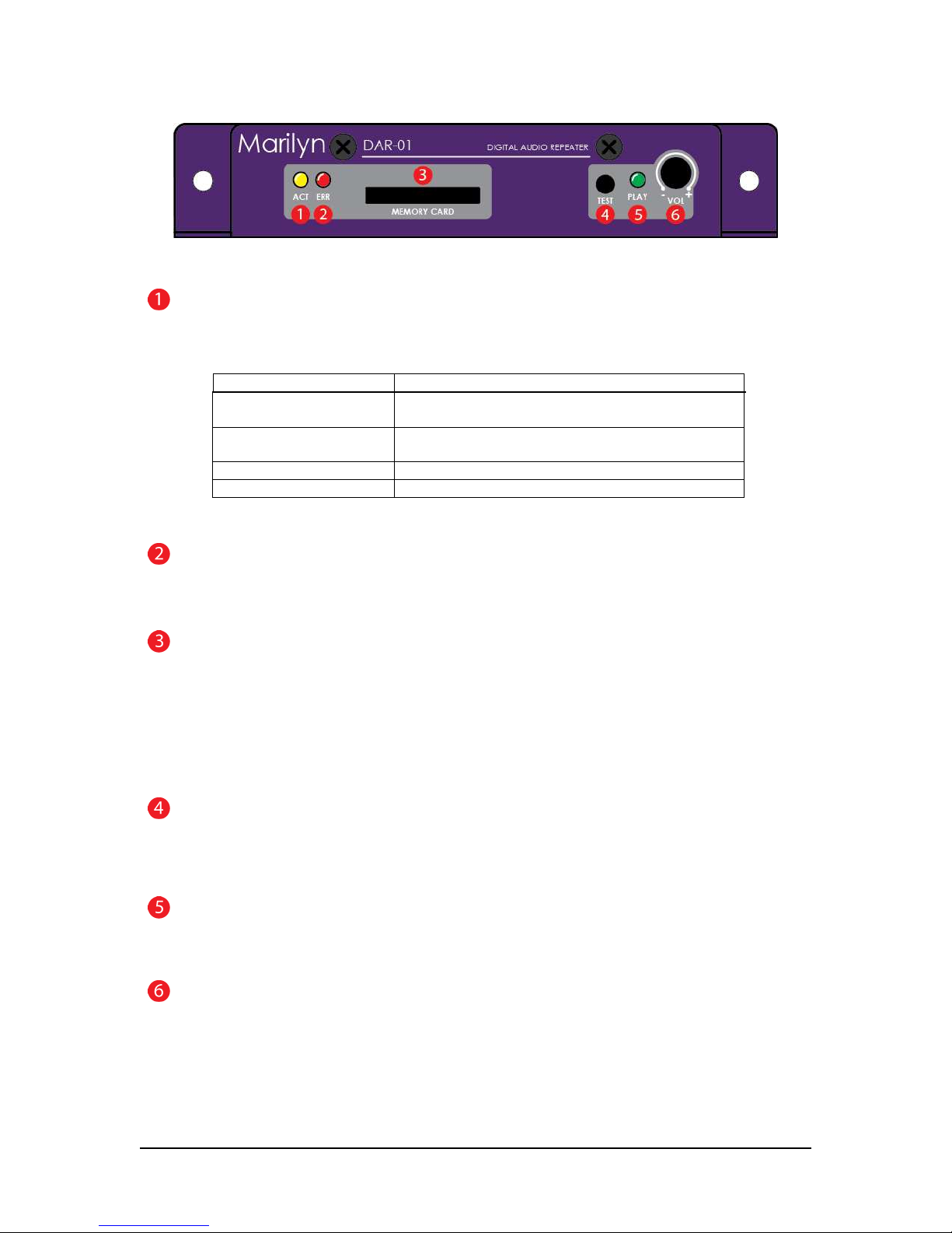
Figure 1 – Front View
ACTivity Indicator
The yellow ACT indicator shows both the current state of the player and any occurring activity.
Indication Function
Slow blink No flash card inserted or no usable configuration
file/media found on the card
Fast blink DAR-01 is reading the configuration file and analyzing
any media present on the flash card
short flash every second Unit is operating normally
½-second flash Indicates input or serial activity
Table 1
ERRor Indicator
The red ERR indicator lights when an issue is present.
MEMORY CARD slot
All sound files and configuration information are stored a SD or SDHC flash memory card. The card is
inserted by gently pushing it into the socket, with the contacts down and towards the DAR-01, until a “click”
is heard. To remove the card, push it in slightly until a “click” is heard. The card is now unlocked and will
be ejected from the socket.
If you wish to prevent removal of the card, an optional guard cover is available.
TEST button
This momentary pushbutton switch provides a user-programmable means of testing the unit. Please refer to
the configuration section for more details.
PLAY LED
The red PLAY indicator lights to indicate that the unit is playing audio
VOLume Potentiometer
This programmable potentiometer provides control over upper and lower limits or can be disabled. Please
refer to the configuration section for more details.
4
2015, Marilyn Systems, llc.
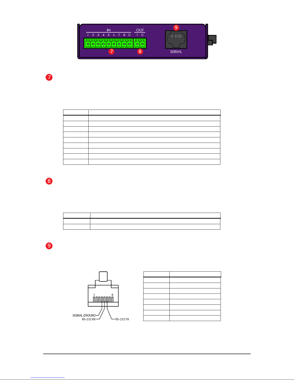
Figure 2 – Left View
INputs Connector
Eight non-polarized, optically-isolated inputs are available for triggering tracks and performing other actions.
The entire group shares a single common. The inputs can accept 12-24VDC and draw a maximum of 10mA.
Please refer to figures 7 & 8 for wiring examples.
Terminal Function
1 Input 1
2 Input 2
3 Input 3
4 Input 4
5 Input 5
6 Input 6
7 Input 7
8 Input 8
C Input Common
Table 2
OUTput Connector
A solid-state relay output is available for various functions. This relay can switch 100mA at 24VDC, enough
to drive a typical electromechanical relay, lamp, or other similar device. Please refer to figures 9 & 10 for
wiring examples.
Terminal Function
C Status output common contact
NO Status output normally-open contact
Table 3
SERIAL Connector
RS-232 port brought out on an EIA-561 compatible RJ-45 jack. See configuration file section for serial port
operating parameters.
Terminal Function
1 NC
2 NC
3 NC
4 Signal Ground
5 DAR-01 Rx
6 DAR-01 Tx
7 Reserved
8 NC
Pin-out (cable-end, connector front) Table 4
2015, Marilyn Systems, llc.
5
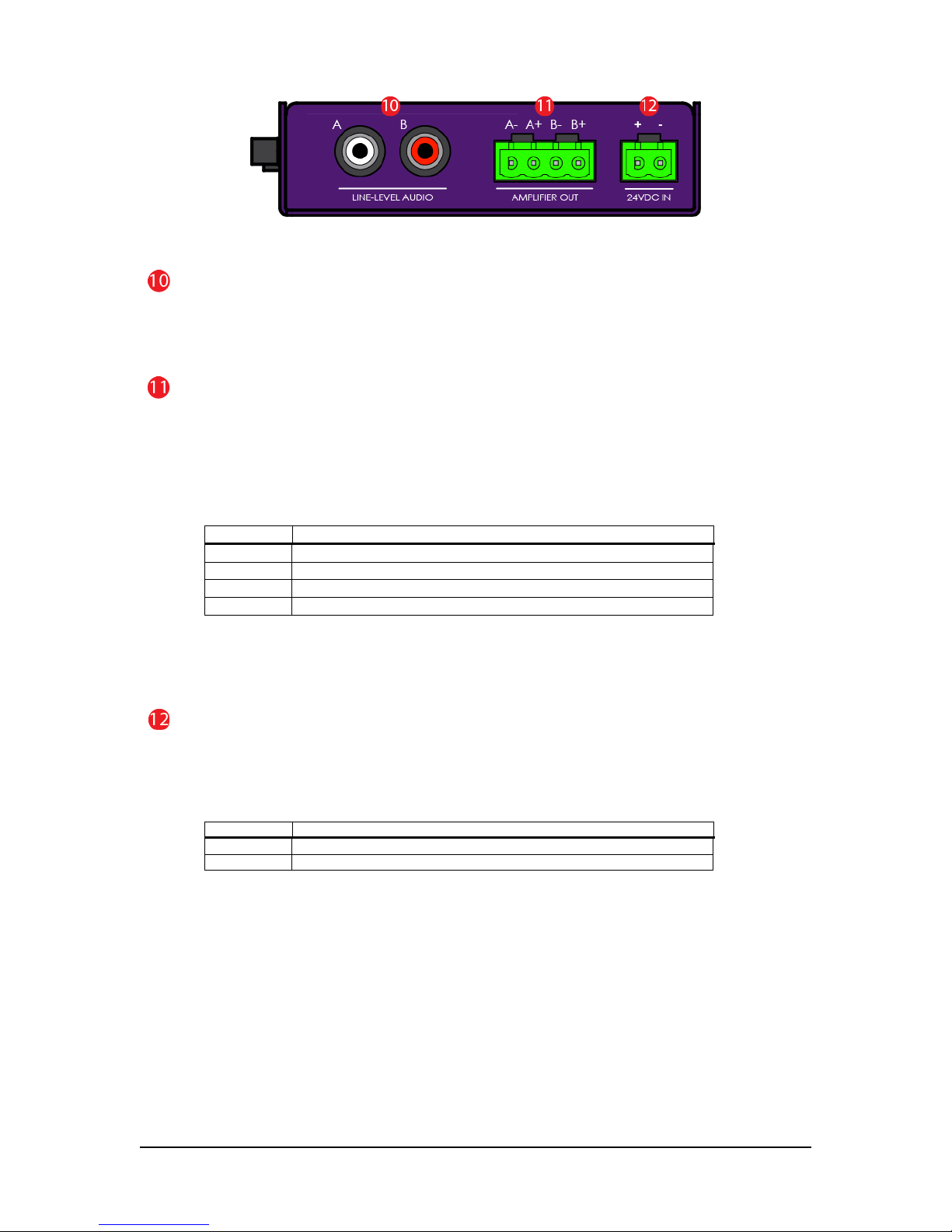
Terminal
Function
+ Power supply positive
- Power supply ground
Figure 3 – Right View
LINE-LEVEL AUDIO Jacks
Two RCA, line-level output jacks marked A (left) and B (right) are provided for connection to an external
audio system. These outputs are always active regardless of the state of the amplifier.
AMPLIFIER OUT Connector
A 40W-per-channel, stereo amplifier which can directly drive a 4 to 8-ohm loudspeaker load (see figure 5).
Optionally, the outputs may be paralleled for a single, 80W output by jumping together both positive
terminals and both negative terminals respectively (see figure 6 for a wiring example). PLEASE NOTE that
a mono audio file
not be used. Please refer to the configuration information below for more details.
Table 5
If you are upgrading from a rev. b or rev. c DAR-01, please notice that the amplifier output pin-outs
have changed.
24VDC IN Connector
The DAR-01 can operate on a little as 12VDC however for optimal amplifier performance, 24VDC should be
provided. With the amplifier enabled, a minimum 100Watt supply should be used.
unregulated supply as this could damage the player. See figure 4 for a wiring example.
must
be used when the outputs are paralleled. The amplifier can be disabled if it will
Terminal Function
A- Channel A (left) negative terminal
A+ Channel A (left) positive terminal
B- Channel B (right) negative terminal
B+ Channel B (right) positive terminal
Do not
use an
Table 6
6
2015, Marilyn Systems, llc.
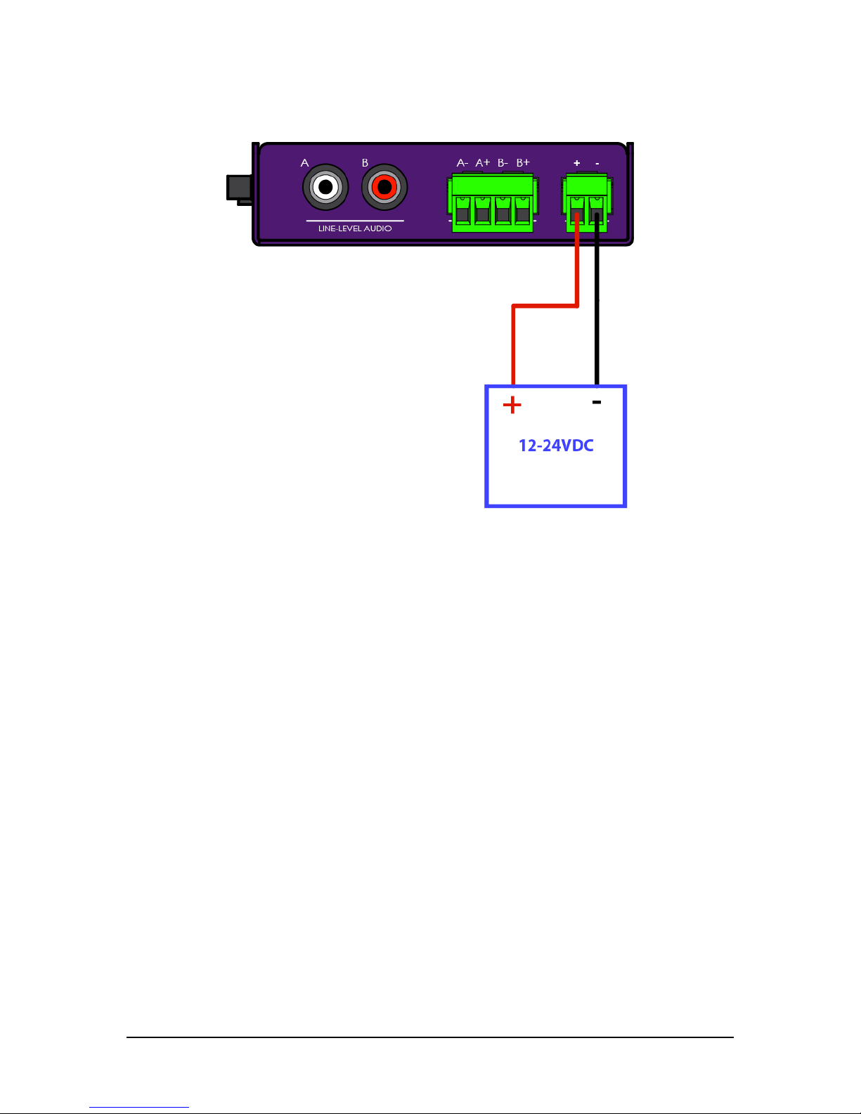
Power Wiring Example
Figure 4 – Power wiring example
2015, Marilyn Systems, llc.
7

Speaker Wiring Examples
Figure 5 – Stereo speaker wiring example
Figure 6 – Mono speaker wiring example (amp paralleled)
8
2015, Marilyn Systems, llc.
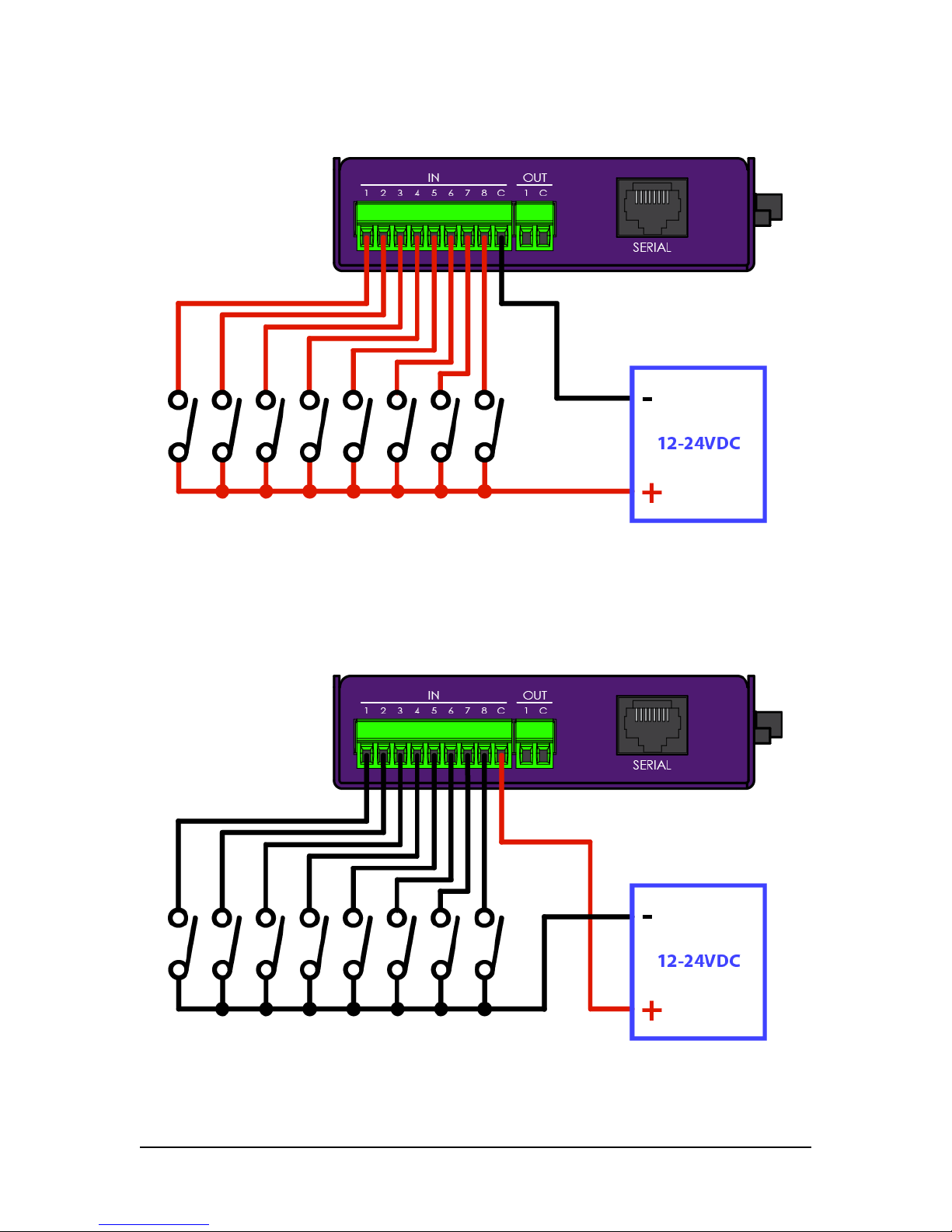
Input Wiring Examples
Figure 7 – Inputs with negative common wiring example
Figure 8 – Inputs with positive common wiring example
2015, Marilyn Systems, llc.
9
 Loading...