

mariel Idea Tronic User Manual
INSTRUCTIONS FOR USE

Index
Description of the device 4
Components 5
Connection of the base to the vacuum pump 6
Switching on the equipment 7
Language and/or contrast modication 7
Connection of 1 - 2 kg. cylinders 8
Connection of 5 - 10 - 12 - 40 kg. cylinders 9
Choice of refrigerant uid - BT, TN, AC and charge method 10
System check up 11
Vacuum 11
Charge
Charge by weight 12
Charge by pressure 13
Refrigerant recovery procedure 14
Check of special systems 15
Display light 16
Switching o the equipment 16
Batteries replacement 16
Decommissioning / Waste disposal 17
Warranty 17
Optional 18 - 19
3
4
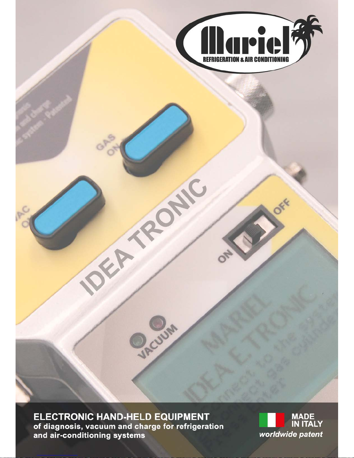
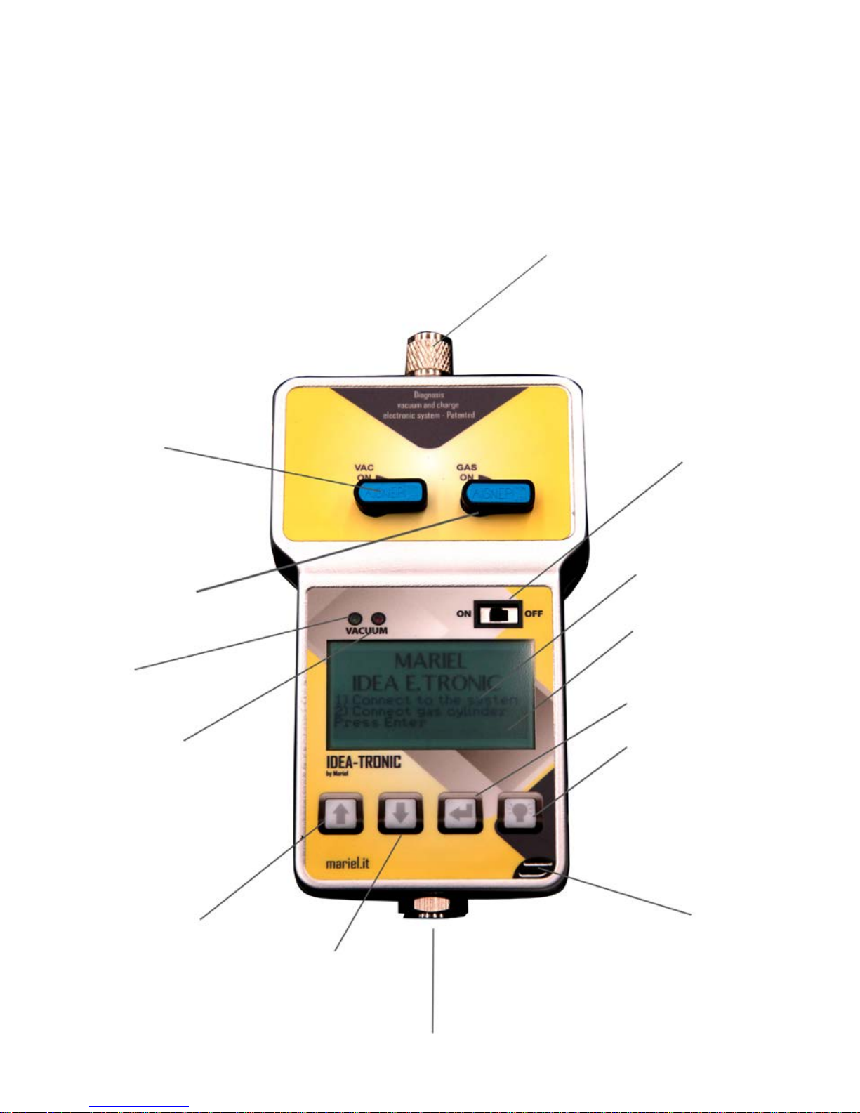
DESCRIPTION OF THE DEVICE
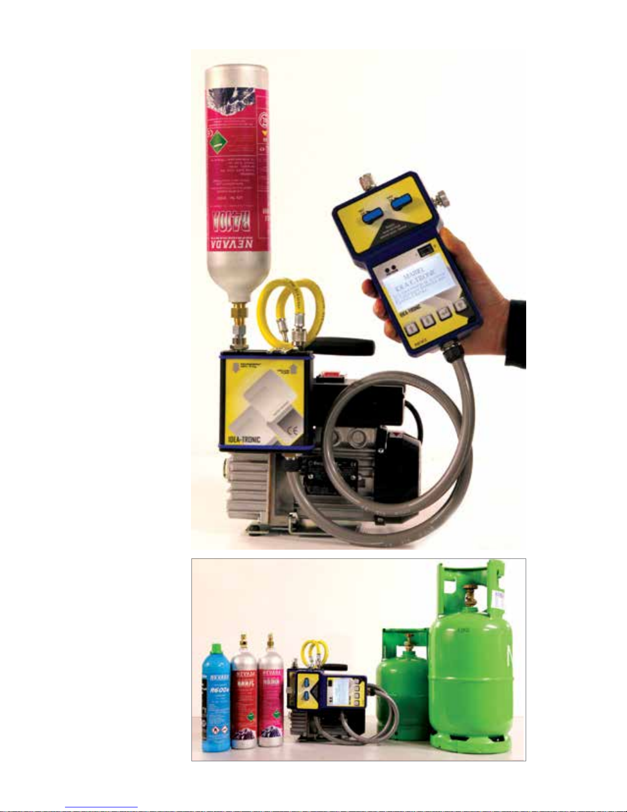
IDEA TRONIC is an “integrated” device composed by two connected parts, a base and a
hand-held equipment which, once connected to any refrigerating or air-conditioning system
will allow you, without more disconnecting, to: 1) RECOVER THE REFRIGERANT GAS,
2) MAKE THE VACUUM, 3) CHECK FOR POSSIBLE LEAKS, 4) MAKE THE CHARGE
WITH GRAM ACCURACY, 5) CHECK IF THE CARRIED OUT CHARGE IS CORRECT.
1. SYSTEM CONNECTION OR
2. EXTENSION
3. VACUUM TAP
4. GAS TAP
5. VACUUM GREEN LED
6. VACUUM RED LED
12. FORWARD KEY
13. BACKWARD KEY
15. BASE CONNECTION
14. THERMOMETER
SENSOR
10. DISPLAY LIGHT
11. ENTER KEY
9. PROGRESS PRESSURES
BAR
8. DISPLAY
7. SWITCH On / O
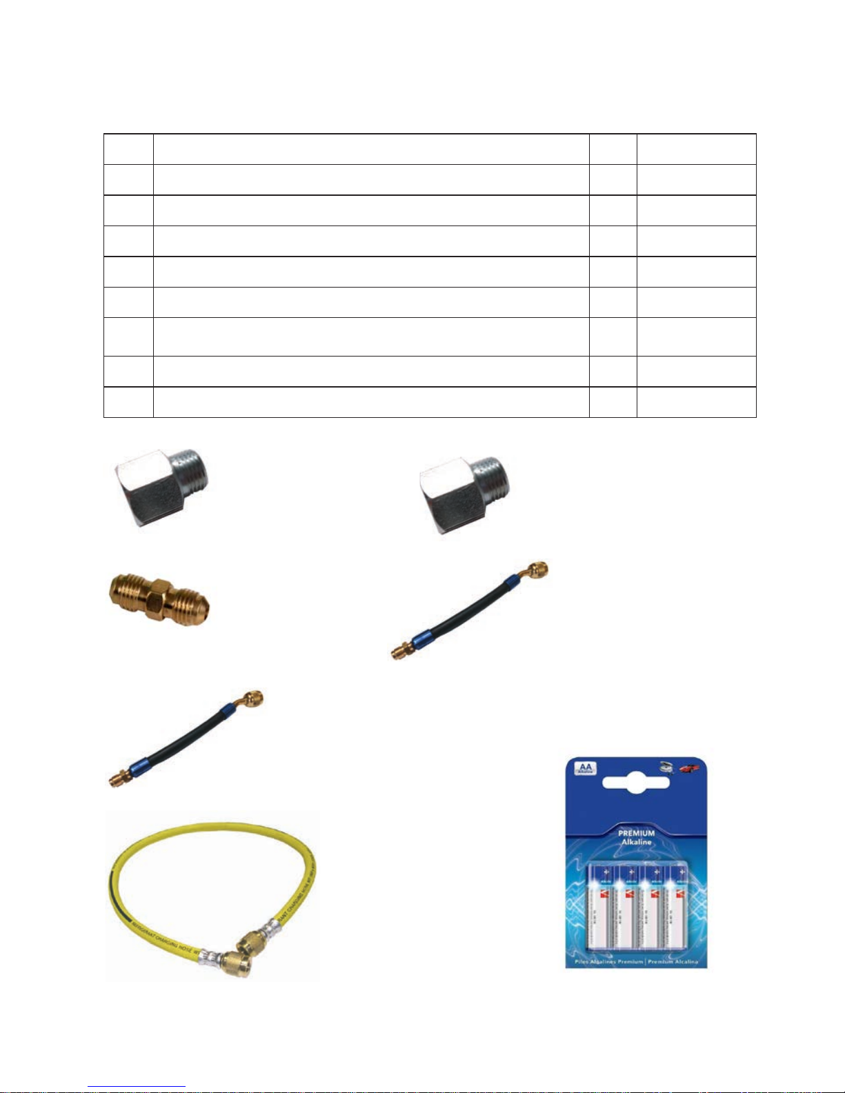
1) 1/4” - 5/16” adapter
for R410A
4) 20 cm. hose 1/4”M - 1/4”F for
R22 - R422B - R407C - R404A
- R134a
5) 20 cm. hose, 1/4”M - 5/16”F
R22 - R422B - R407C - R404A - R134a
6) Connecting hose for vacuum
pump
7) Batteries mod. AA
3) Nipple for cylinders of
5 - 10 - 12 - 40 Kg.
2) 1/4” - 1/4” adapter for
R22 - R422B - R407C - R404A
- R134a
5
Q.ty DESCRIPTION Pic. CODE
1
Complete device, 2 parts: base / hand-held equipment IDEAT
1
Brass adapter 5/16” F - 1/8“ M. - with aerosol M. connection
1
ADATTATORI5/16
1
Brass adapter 1/4” F - 1/8“ M. - with aerosol M. connection
2
ADAT TATORI
1
Nipple 1/4” M - 1/4” M. for the connection of 5 - 10 - 12 - 40 kg. cylinders
3
MA30
1
Connecting hose of 20 cm., 1/4” sae M. - 5/16” F.
4 D20008
1
Connecting hose of 20 cm., 1/4” sae M. - 1/4” sae F
5 D20007
1
Yellow connecting hose for vacuum pump
6 D20005
4
Battery of 3 Volts mod. AA
7
D70001
COMPONENTS OF THE KIT
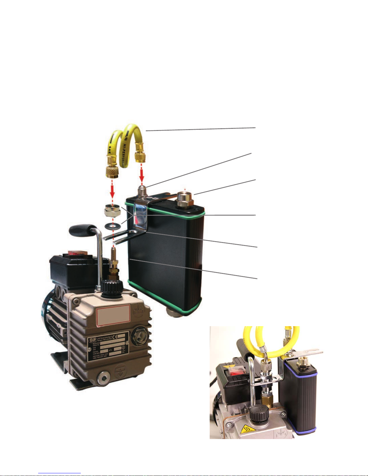
CONNECTION OF THE BASE TO THE VACUUM PUMP
6
1 - Screw the 1A nut (point 6) on the vacuum pump connecting port.
2 - Put the bracket (point 5) on the base of the 1A nut and screw it with 1B nut +
washer (point 4).
3 - Connect the yellow hose (point 1) to the 1A nut and to the vacuum connecting port
of the Idea Tronic (point 2).
4 - Select the appropriate reduction before screwing the cylinder (check page 8).
5. Bracket
6. 1A nut
Example of an appropriate connection
4. 1B nut + washer
3. Cylinder connecting port
(use the adapter if necessary)
1. Hose for vacuum
pump connection
2. Vacuum port of Idea
Tronic base
 Loading...