

Page 1

eLea™
Home Care Installation
Manual
Page 2
Home Care Installation Manual
MariCare Professional Care Solutions for Elderly Care Sector
Copyright © MariCare™, Finland
No part of the contents of this document may be reproduced or duplicated
without the prior written permission of MariCare™. The data published
corresponds, under reservation of all our rights, to the most recent information
at the moment of publication and is subject to future modification. MariCare™
reserves the right to modify the contents of this document at any time. No
rights can be derived from this publication.
e
Lea™ is a trademark of MariCare™
Page 3

MariCare Oy, www.maricare.com 3 (32)
CONTENTS
1. Introduction
2. Overview of the eLea™ System
3. eLea™ Smart Detector Working Range
4. Installing an eLea™ Smart Detector Unit
5. Communication Installations
6. Setting up the System
7. Activity Indicators
8. Appendices
Page 4

MariCare Oy, www.maricare.com 4 (32)
1. INTRODUCTION
MariCare™ is the leading provider of Professional Care Solutions for
the Elderly Care sector. Since its introduction to the market in 2005,
Elsi® Care Solution with the Elsi® Smart Floor, has been the
unchallenged forerunner in its field, and has been selected by many
new Elderly Care facilities for its performance, uniqueness and newly
innovated features for improved service and quality.
e
Lea™ Activity
Sensing is the newest solution, specially developed for existing
Healthcare facilities & Home Care.
This manual is specifically for
• Home Care installations, includes small Elderly Care Homes,
Nursing Homes, Rehabilitation Homes, and private Homes.
• Retro fitting existing facilities, which may/will already contain
fire detection sensors, nurse call systems, phones, etc. but
still requires a fall detection system
e
Lea™ Activity Sensing is a wireless solution and the installation of
the devices requires accurate positioning to allow the sensor to
function perfectly and always provide the best service for which it has
been designed.
This document includes
• An overview of the equipment
• The theory and method for positioning the equipment
• The Installation procedure for the equipment
1.1 PERSONNEL QUALIFICATIONS FOR
MAINTENANCE WORK
Note: All eLea™ Activity Sensing products are easy to install, but
installation, maintenance and service work needs to be carefully
made according to instructions.
Page 5
MariCare Oy, www.maricare.com 5 (32)
2. OVERVIEW OF THE eLea™ HOME CARE SYSTEM
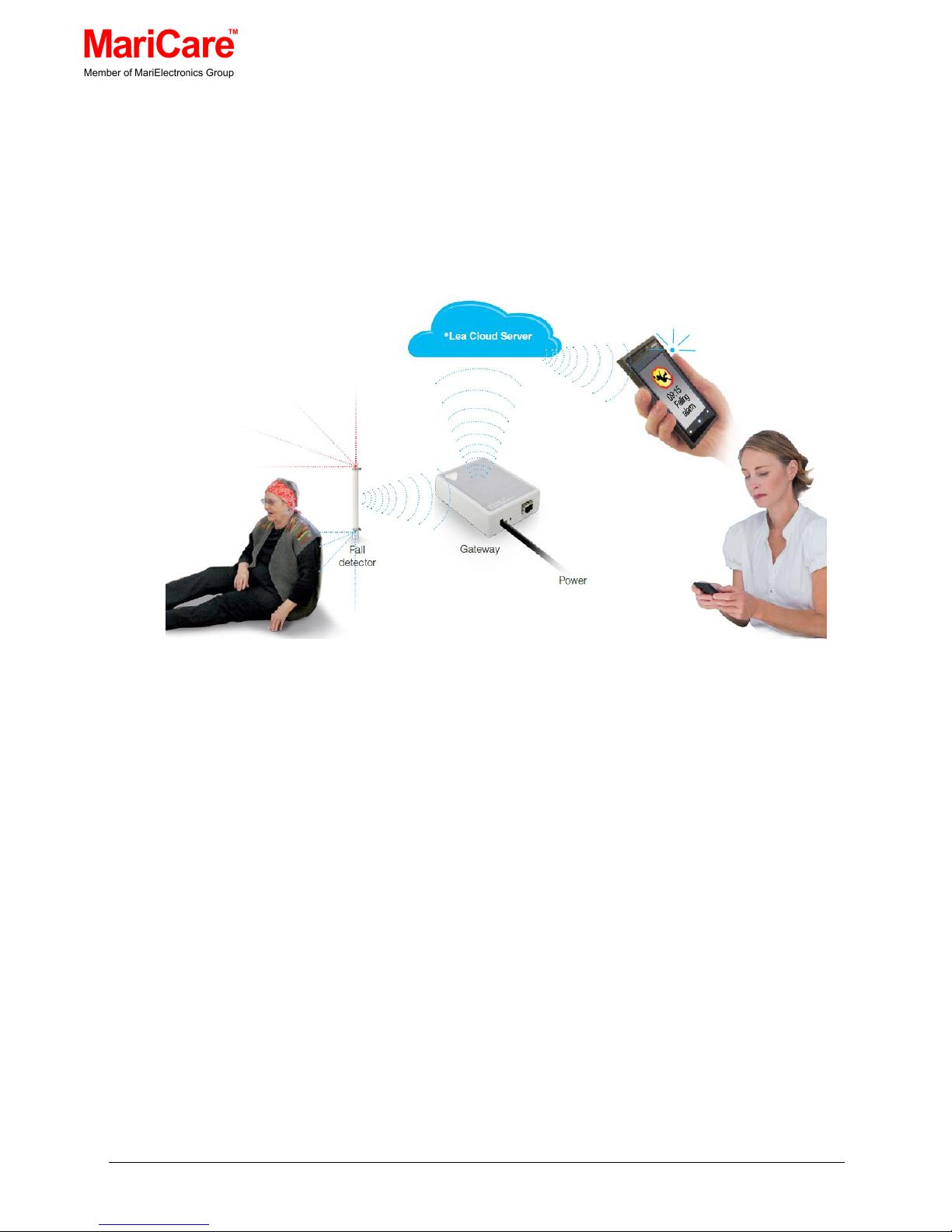
All
e
Lea™ products are based on wireless “EnOcean®” technology.
The
e
Lea™ components communicate and send the fall, burglar or
fire alarm to the
e
Lea™ Gateway, which is connected to the eLea™
Server via internet or 3G.
Figure 2.1 Overview of the eLea™ Home Care System
Page 6

MariCare Oy, www.maricare.com 6 (32)
2.1
e
Lea™ SOLUTION FUNCTIONS
The eLea™ Activity Sensing Solution has a full complement of
standard and optional functions that can cover every situation for
elderly care.
Equipment
Description/Comments
e
Lea™ Activity Sensing
Solution to detect a person
falling
Sends a signal if both sensors first see
movement by an infrared source, followed
by only the lower sensor seeing
movement by the infrared source.
e
Lea™ Activity Sensing
Solution to detect activity
Sends a signal when both sensors see
movement by an infrared source and no
prior activity has been detected for a
specified time (configurable by software).
Door Monitor
Sends a signal when the door is open
Switch
Alarm button eg. toilet/bed
eLea Bracelet
Alarm Bracelet for Summoning Help
Lighting Control
Switches on the lighting when movement
indicates the resident is out of bed
Burglar Alarms
Optional-Special System Design
Switching off the electricity when
leaving premises
Optional-Special System Design
Shutting off the water when
leaving premises
Optional-Special System Design
Adjusting the room temperature
when leaving premises
Optional-Special System Design
Table 2.2 eLea™ Activity Sensing Equipment
Page 7
MariCare Oy, www.maricare.com 7 (32)
3. eLea™ ACTIVITY SENSING WORKING RANGE
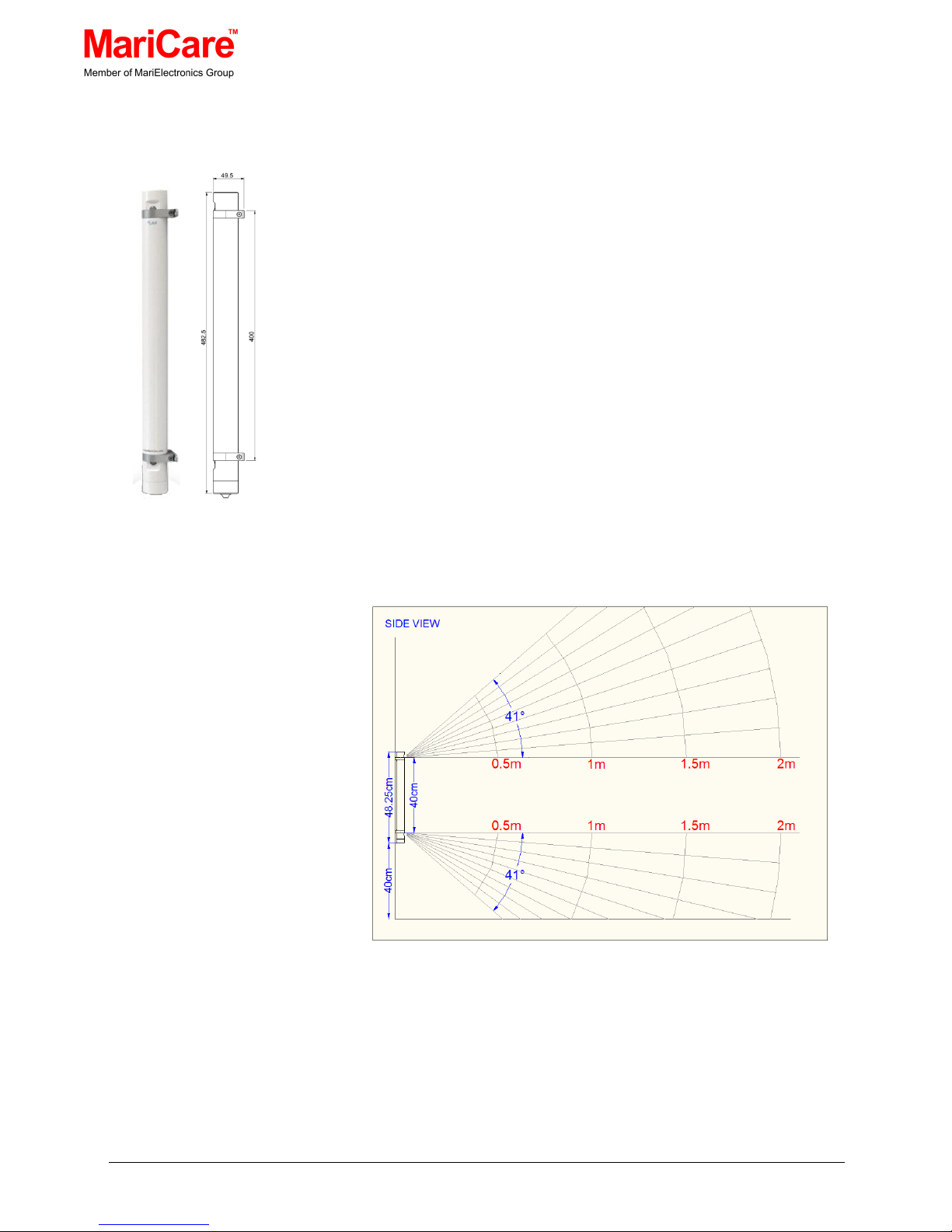
The eLea™ Activity Sensing is a tubular, waterproof device (IP44). Its
body length is 482.5 mm and when fixed to a wall, it stands out from
the wall 49.5 mm.
The small indentations on the side of the tube at the top and the
bottom of the detector are where the PIR (Passive Infrared) sensors
are located.
It is essential that the eLea™ Activity Sensing concept is clear, so
fitters can install the detector with an in-depth understanding of the
necessity to position the detector with the utmost accuracy.
The eLea™ Activity Sensing have a specific operational range and
direction.
The vertical detection angles of the eLea™ Activity Sensing’ two PIR
sensors are shown in Figure 3.2.
Figure 3.2 Vertical Detection Angles
The detector must be positioned so that the detection angle of the top
sensor ranges from horizontal upwards to an angle of 41°, while the
detection angle of the bottom sensor ranges from horizontal
downwards to an angle of 41°. The separate infrared sensors retrieve
Figure 3.1 eLea™
Activity Sensing
Page 8
MariCare Oy, www.maricare.com 8 (32)
independent information that is analysed by the eLea™ Activity
Sensing.
With this in mind, the eLea™ Activity Sensing is positioned at a
suitable location on a wall with its lower end 400 mm above the floor.
The eLea™ Activity Sensing must be fixed vertically in a position to
ensure the horizontal angle of the sensors.
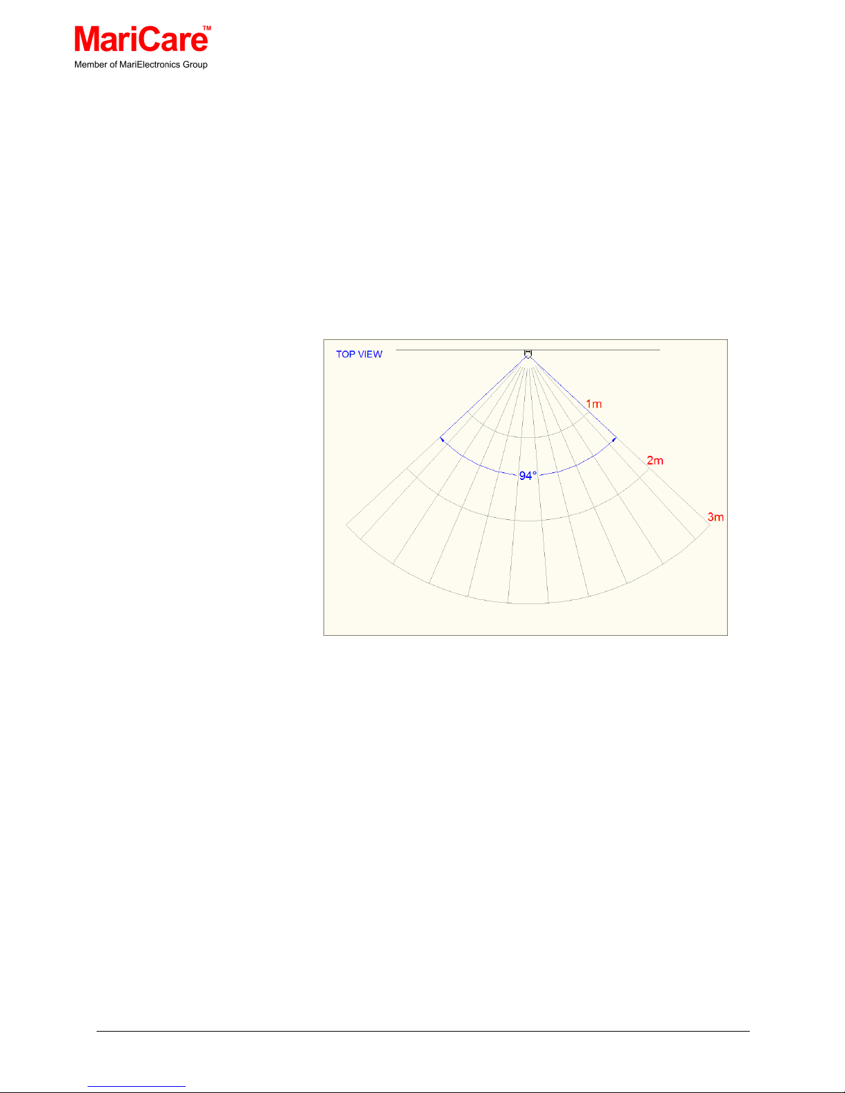
Before the eLea™ Activity Sensing is finally secured, the position of
the horizontal detection angle must be adjusted to the correct
position. The range of the horizontal detection angle is 94°as shown
in Figure 3.3.
Figure 3.3 Horizontal Detection Angle
The detector should be rotated so that this range of 94°
encompasses the area of the room or space that is required to be
surveyed.
Other points when deciding on the location of the eLea™ Activity
Sensing:
• The sensitivity of PIR sensors decreases with distance, which
in practice means that the farther away a person is from a
PIR sensor; the more exaggerated movement must be to
trigger a response from the eLea™ Activity Sensing
• Ideally, the best PIR sensor response is achieved within 3
metres of the eLea™ Activity Sensing
• The maximum detection range is 5 m
Page 9
MariCare Oy, www.maricare.com 9 (32)
3.1 HOW AN eLea™ ACTIVITY SENSING
WORKS
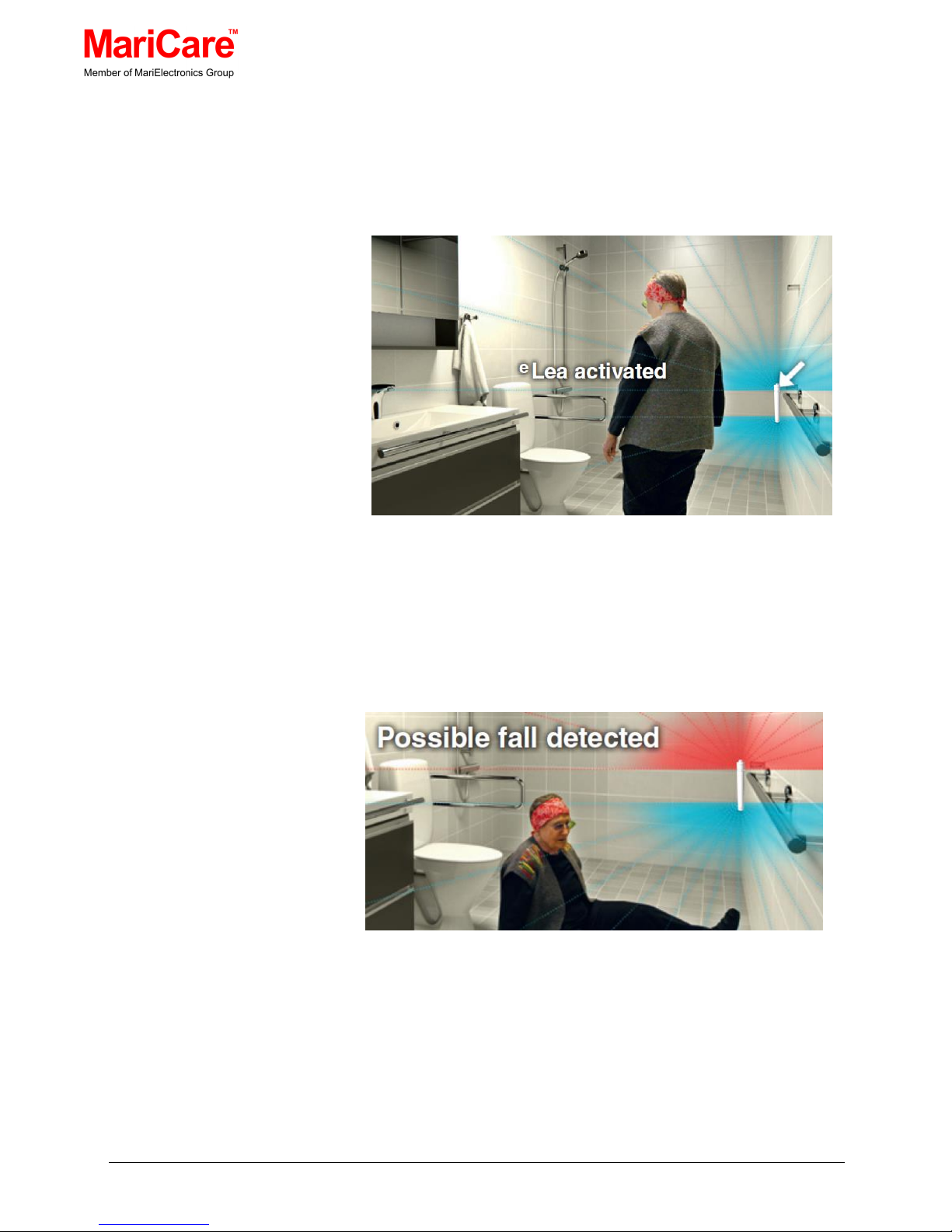
When an eLea™ Activity Sensing is active, it detects infrared from the
area it has been designed to survey.
Figure 3.4 Both Bottom and Top PIR Sensor detects the Presence of
a Person
When a person enters the surveyed area both sensors pick up the
presence (viz. IR and movement) of the person as shown in Figure
3.4.
Figure 3.5 Only the Bottom PIR Sensor now detects the Person,
triggering an Alarm
If a person falls while still within the range of the device as shown in
Figure 3.5, the top sensor cannot now detect the presence of the
person while the bottom one can, which causes the eLea™ Activity
Sensing to send out a fall alarm.
Page 10
MariCare Oy, www.maricare.com 10 (32)
3.2 POSITIONING DETECTORS
An accommodation unit will have a WC and one or two living areas.
One or two eLea™ Activity Sensing detectors are required in the WC,
and one or more in each living space.
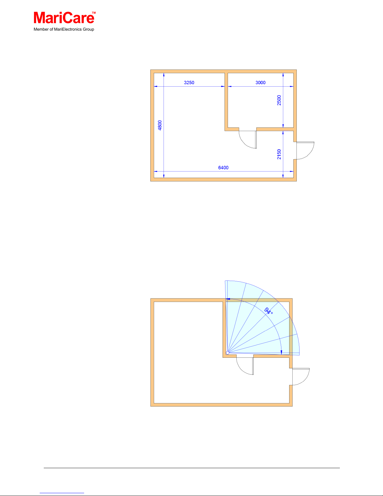
Figure 3.6 Example of an Accommodation Unit
Typically, the WC will include a washbasin, toilet and shower. The
e
Lea™ Activity Sensing detectors should be placed in a position so
that neither the toilet bowl nor washbasin becomes an obstruction to
the eLea™ Activity Sensing’s field of view.
Figure 3.7 Positioning an eLea™ Activity Sensing in a WC
Page 11
MariCare Oy, www.maricare.com 11 (32)
The living area needs more consideration. A living area with perhaps
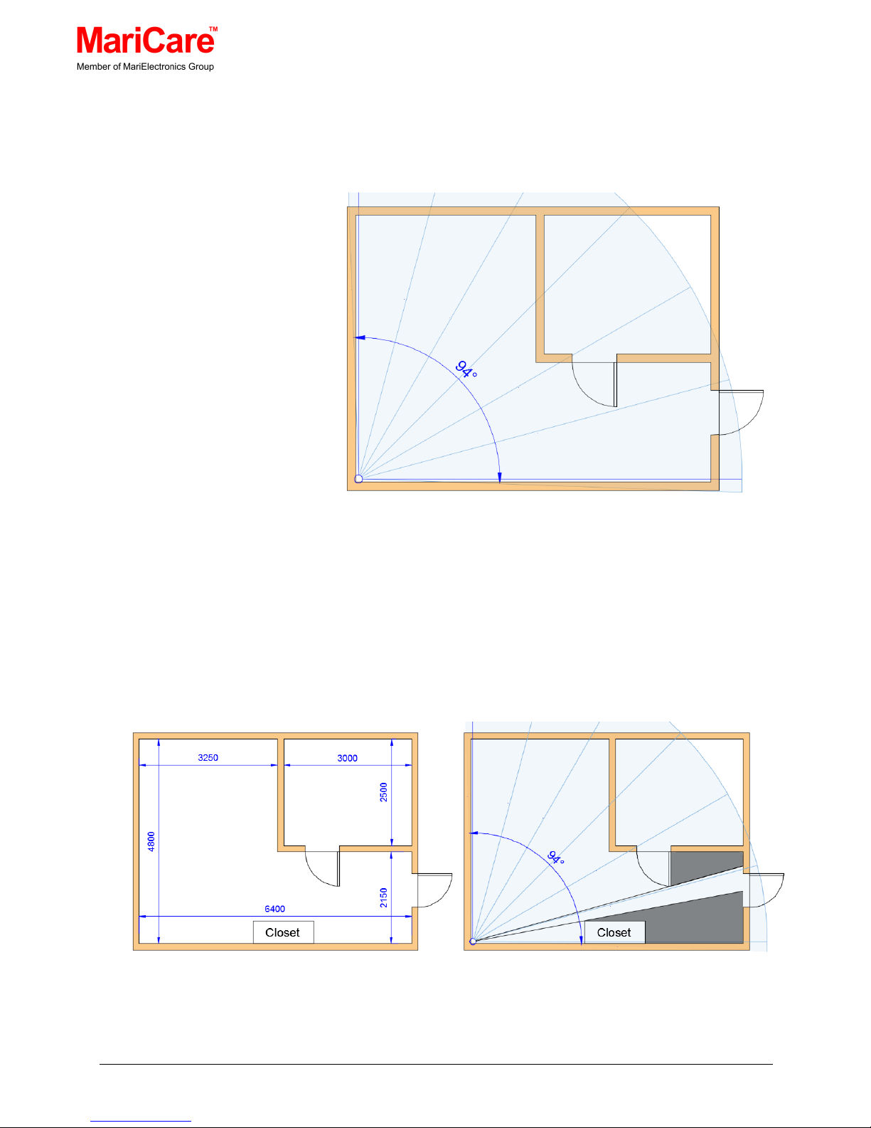
a bed, bedside table, etc. such as in Figure 3.8
with the WC door expected to always be closed could be served by a
single eLea™ Activity Sensing but that is seldom the case.
Figure 3.8 Positioning an eLea™ Activity Sensing in an Unobstructed
Room
In Figure 3.9 it can easily be seen that a piece of furniture and the
WC door left open limits the eLea™ Activity Sensing’s field and the
entrance to the accommodation is hidden from the eLea™ Activity
Sensing’s field range. See the blue shaded area on the figure, which
indicates the obstructed area.
Figure 3.9 Obstructions will limit the Detectors Field of View
Page 12
MariCare Oy, www.maricare.com 12 (32)
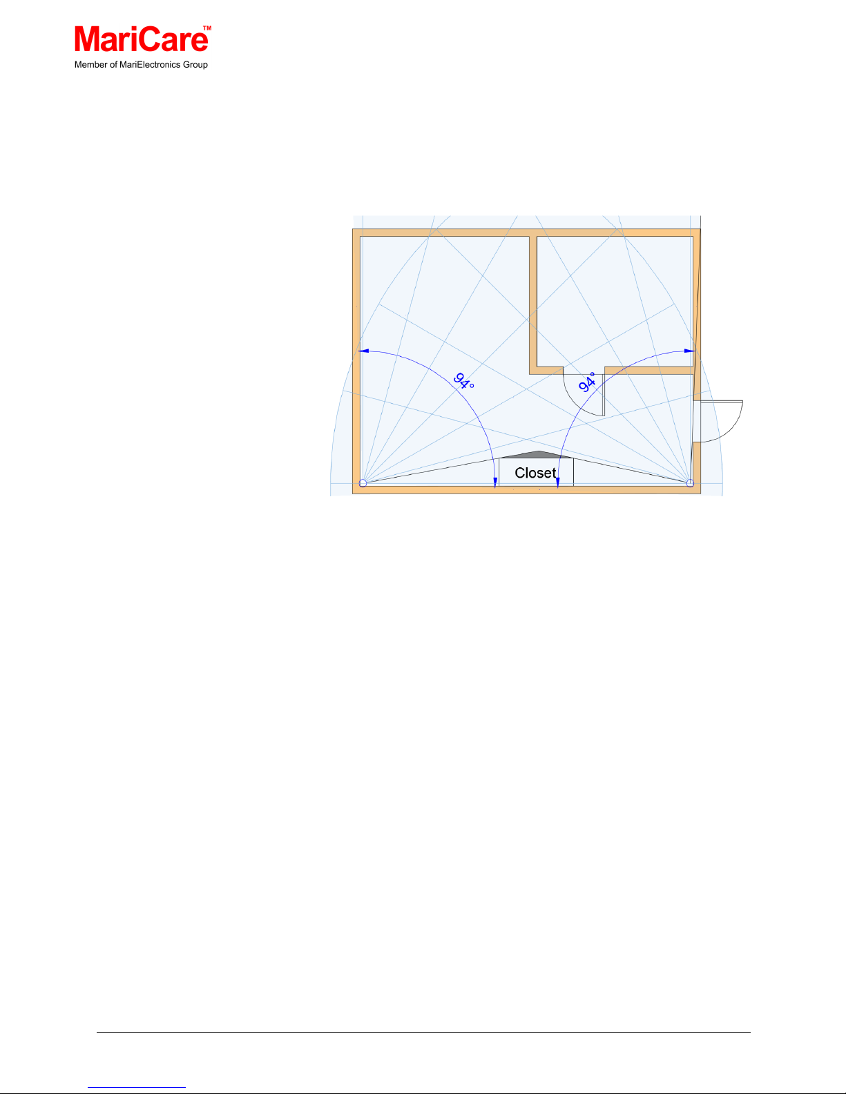
To compensate for these obstructions, a second eLea™ Activity
Sensing is installed at the accommodation’s entrance as shown in
Figure 3.10.
Figure 3.10 A Second eLea™ Activity Sensing eliminates the Problem
of the Obstructed Area
It immediately becomes obvious the living area shown in
Figure 3.10 is now within the range of one or both detectors.
See the blue shaded area on the figure, which indicates the
obstructed area.
It is therefore necessary to check that the eLea™ Activity Sensing(s)
have an unobstructed field of view to operate in, and if an obstruction
comes within the field of view, either or both of the eLea™ Activity
Sensing(s) should be relocated to the optimum position or one or
more extra eLea™ Activity Sensing(s) should be installed to cover
each obstructed area in the room.
Note: Ideally, an eLea™ Activity Sensing should not be positioned in
a way that it faces out of an open doorway or window, as it may
detect movement unrelated to the activities within the controlled living
space.
Page 13
MariCare Oy, www.maricare.com 13 (32)
4. INSTALLING AN ELEA™ ACTIVITY SENSING UNIT
Once the eLea™ Activity Sensing theory and practice is understood,
the fitter has no difficulty appreciating what is required.
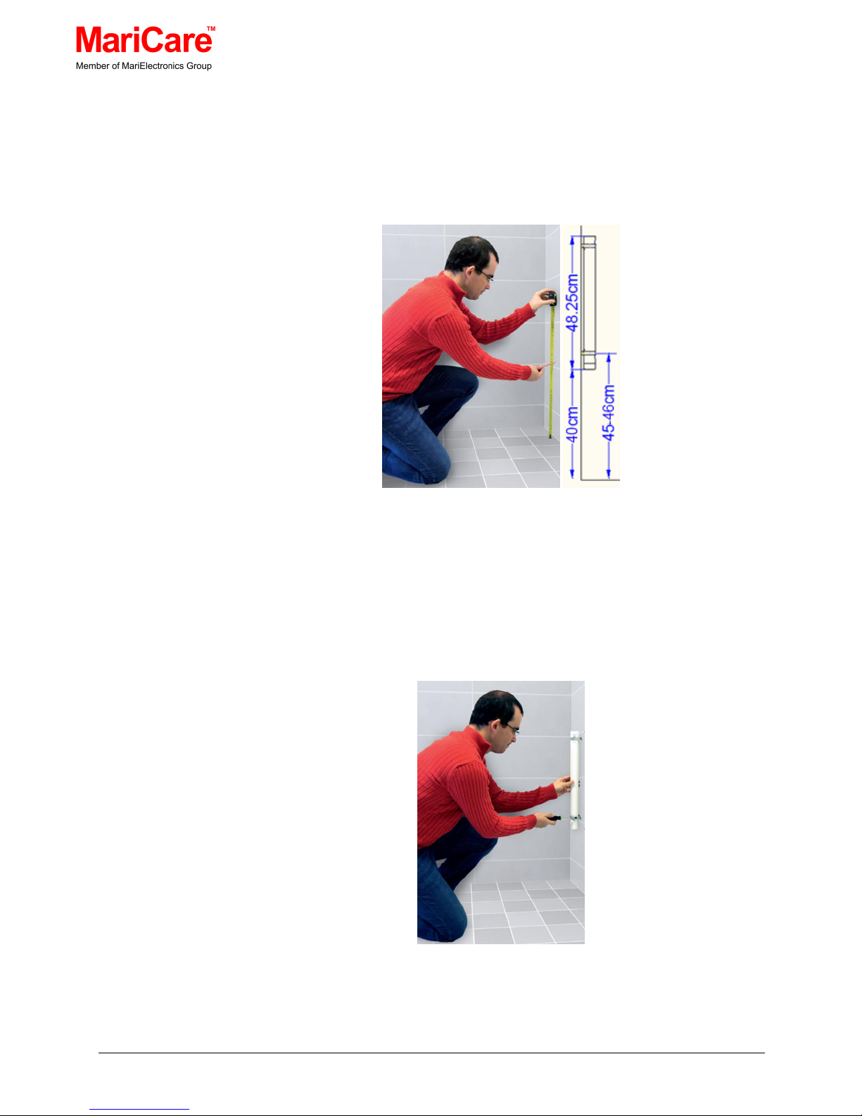
Figure 4.1 Mark the Height of the eLea™ Activity Sensing Clamps
• The positions of the holes to be drilled in the wall for securing
the lower the eLea™ Activity Sensing clamp are marked (i.e.,
about 45-46 cm above the floor), the holes are drilled and the
e
Lea™ Activity Sensing lower clamp is screwed lightly in
place on the wall. See Figure 4.2.
Figure 4.2 Secure the Lower the eLea™ Activity Sensing Clamp lightly
in Place
Page 14

MariCare Oy, www.maricare.com 14 (32)
• The eLea™ Activity Sensing must be checked with a spirit level in
both vertical directions before the holes to be drilled for the upper
clamp are marked, the holes are drilled and then the eLea™
Activity Sensing clamp wall screws are tightened firmly in place
• When the vertical alignment is assured, the eLea™ Activity
Sensing clamp’s locking screws are sufficiently loosened to allow
the eLea™ Activity Sensing tube to be swivelled in the clamps
until the horizontal detection angle of the eLea™ Activity Sensing
encompasses the correct area of the room or place to be
surveyed.
• Once the eLea™ Activity Sensing has been positioned
satisfactory both vertically and horizontally, the holding screws
can be tightened, so the detector is fixed firmly in place
Note: If the wall where the eLea™ Activity Sensing is placed is out of
vertical alignment, the eLea™ Activity Sensing clamp screw
placements can be shimmed with washers to ensure the vertical
alignment of the eLea™ Activity Sensing on the wall.
Note: The FD05R and the FD05R9V versions of the eLea™ Activity
Sensing are wireless; however, the FD05CR version will need a
connecting power cable and power supply. See section 8
Appendices.
Page 15
MariCare Oy, www.maricare.com 15 (32)
5. COMMUNICATION INSTALLATIONS
Once the eLea™ Activity Sensing(s) are in place, the units
communication equipment can be installed.
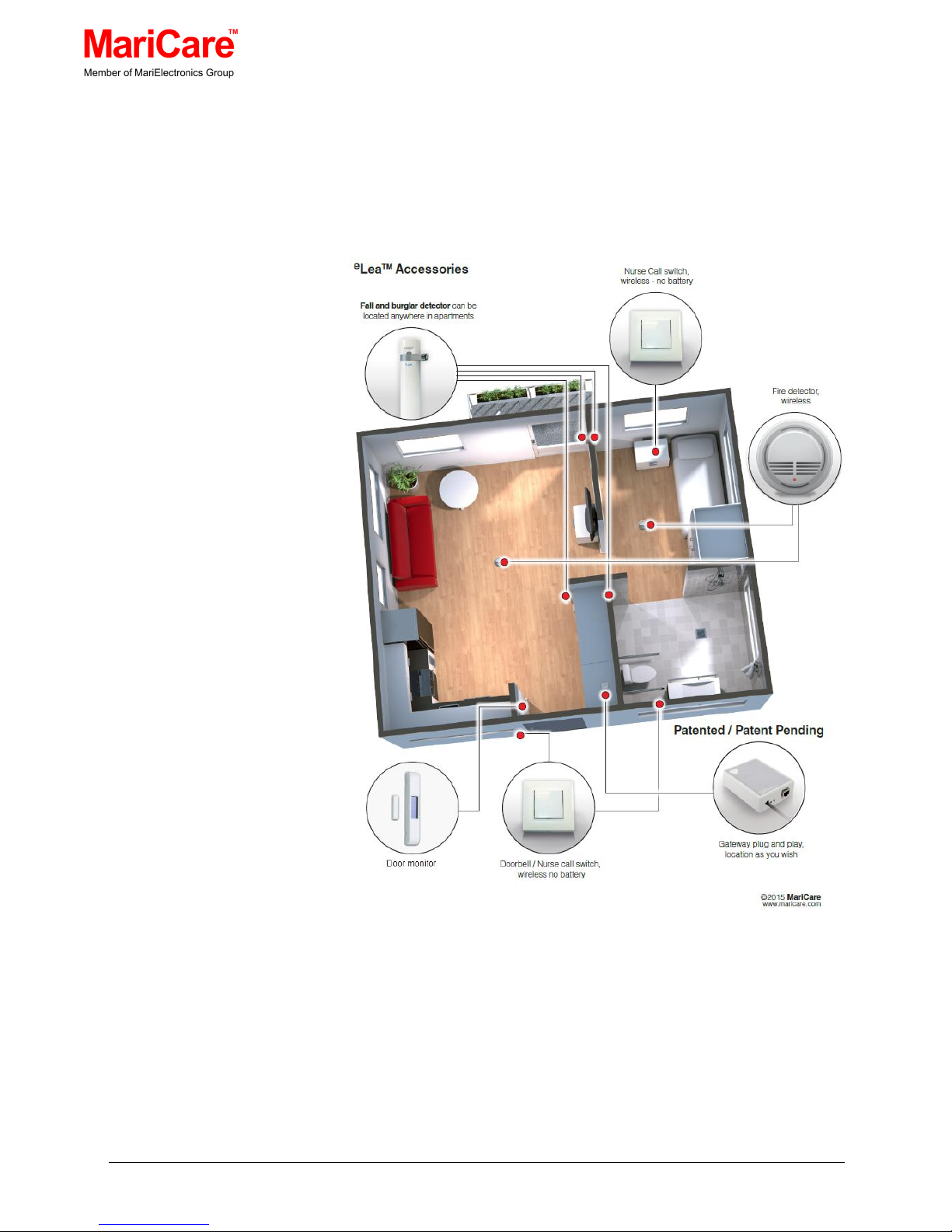
Figure 5.1 Example of eLea™ Activity Sensing Equipment Locations
The Gateway has a maximum range of 15 m, and as long the
associated eLea™ Activity Sensing equipment is within that range,
there should be adequate communication between the gateway and
all of the system’s home care components.
Page 16
MariCare Oy, www.maricare.com 16 (32)
Structural considerations should be taken into account when
installing communications equipment.
See section 5.1 Installation Considerations
The Gateway requires a power supply and an Ethernet connection.
The Ethernet needs to be connected to a router or modem that
provides Internet access and has DHCP enabled.
All other eLea™ Activity Sensing Equipment is working with wireless
and their location is determined solely by their function.
This equipment includes,
• Nurse call switch outside the entrance
• Nurse call switch by the bed
• Fire detectors on the ceiling
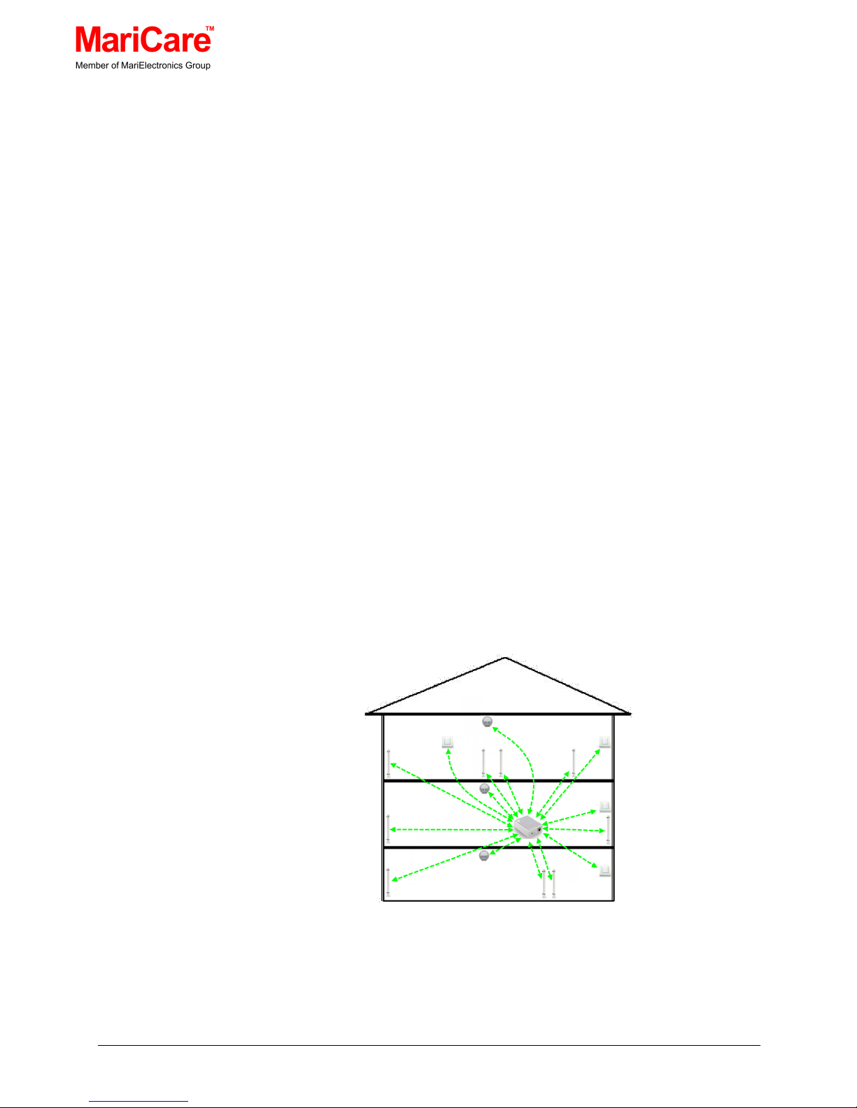
In a house where the floors and walls are constructed of light material
such as wood, a single centrally-placed gateway will have a signal
intensity that is enough for all of eLea™ Activity Sensing equipment in
the building.
Figure 5.2 Example of eLea™ System with a Single Gateway
Page 17

MariCare Oy, www.maricare.com 17 (32)
5.1 INSTALLATION CONSIDERATIONS
The building structure must be considered when planning the
installation for an eLea™ system layout.
• If the partitioning structure between rooms is of dense material
(e.g. reinforced concrete, stone, steel, etc.), it reduces the
intensity of the signals passing through it; however, if the
partitioning structure is of light material (e.g. gypsum board,
plywood, etc.), it will have an insignificant effect on the intensity of
the signals passing through it
• Solid objects (e.g. heavy furniture, pianos, stairs, etc.), objects
made from metal (e.g., cabinets, lockers, ventilation ducts, etc.)
and interference from electronic equipment can disturb and affect
the intensity of the signals. Test all device locations to make sure
the radio telegrams are delivered. If necessary move the gateway
to a better position, so all devices are within range.
• Each gateway controls a circular area of 15 meter radius. A
greater distance from the gateway may be possible in ideal
circumstances.
Page 18
MariCare Oy, www.maricare.com 18 (32)
6. SETTING UP THE SYSTEM
The following sections describe the steps for setting up an
e
Lea™
System through an Internet browser.
6.1 ACCESSING THE SYSTEM
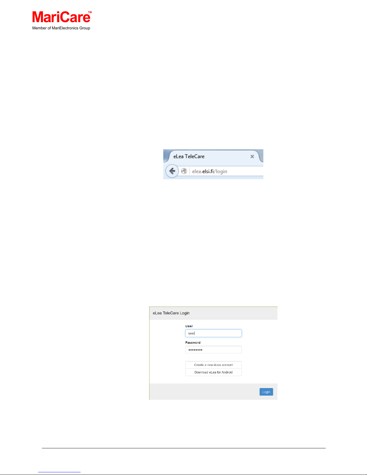
The system is set up using the elea.elsi.fi web site provided by
MariCare™.
Figure 6.1 eLea™ System Web Site Address
Note: the
e
Lea™ System web site address automatically starts by
displaying the Login dialogue window.
6.2 USER ACCOUNT
The first time the system is used, the user must create an account.
After that the user can login by entering the user name and password
as in
Figure 6.2.
Figure 6.2 Logging in to the eLea™ System
Page 19
MariCare Oy, www.maricare.com 19 (32)
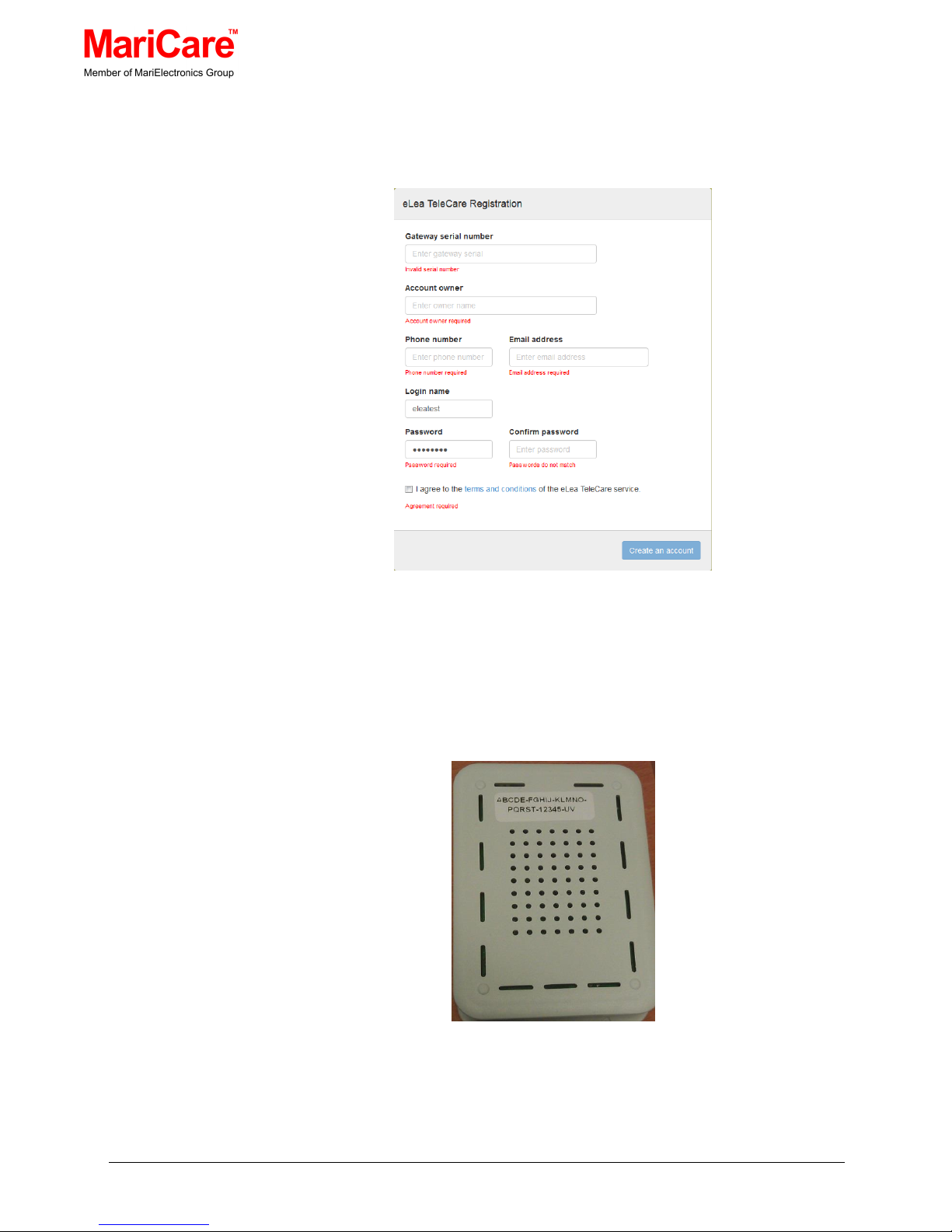
In the registration phase enter all the required information in the
‘eLea Telecare Registration’ dialogue window.
Figure 6.3 eLea™ TeleCare Registration
The gateway serial number can be found on the underside of the
device as show in
Figure 6.4.
Figure 6.4 Serial Number
Page 20

MariCare Oy, www.maricare.com 20 (32)
6.3 USER INTERFACE OVERVIEW
Figure 6.5 eLea Activity Sensing user interface overview
The overview of the shows the name of the resident, daily activities
and the routines in the past 8 days as well as the activities and
recent alarms.
6.4 RESIDENT PRESENCE
House icon tells if the resident is inside the house or outside. In the
example below, the resident has been inside for 4 hours.
The color of the icon is white when the resident is inside.
When the resident is outside the color changes as follows:
0 - 4 hours => green
Page 21
MariCare Oy, www.maricare.com 21 (32)
4 - 8 hours => yellow
8 - hours => red
The resident is considered to have left the house, if the last motion
detection was from a detector located in the entrance of the house
and 5 minutes has passed without detections from other motion
detectors.
6.5 LATEST MOTION
The walking man field tells the time elapsed since the last motion
detection from inside the house. It also gives the name of the
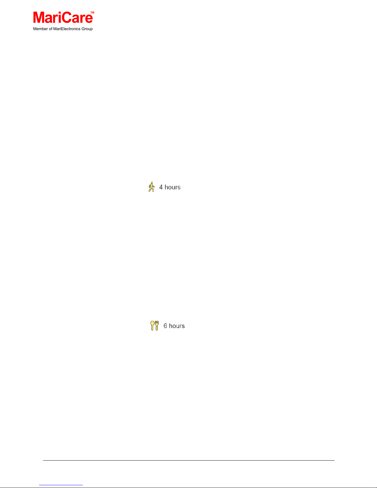
detector that did the detection. In the example below, the resident
has been inside for 4 hours.
The color of the icon changes as follows:
0 - 4 hours => green
4 - 8 hours => yellow
8 - hours => red
6.6 MEAL
The meal field tells the time elapsed since the door of the refrigerator
was last opened. In the example below, the resident has not opened
the refrigerator for 6 hours.
The color of the icon changes like above:
0 - 4 hours => green
4 - 8 hours => yellow
8 - hours => red
Page 22
MariCare Oy, www.maricare.com 22 (32)
6.7 TOILET VISITS
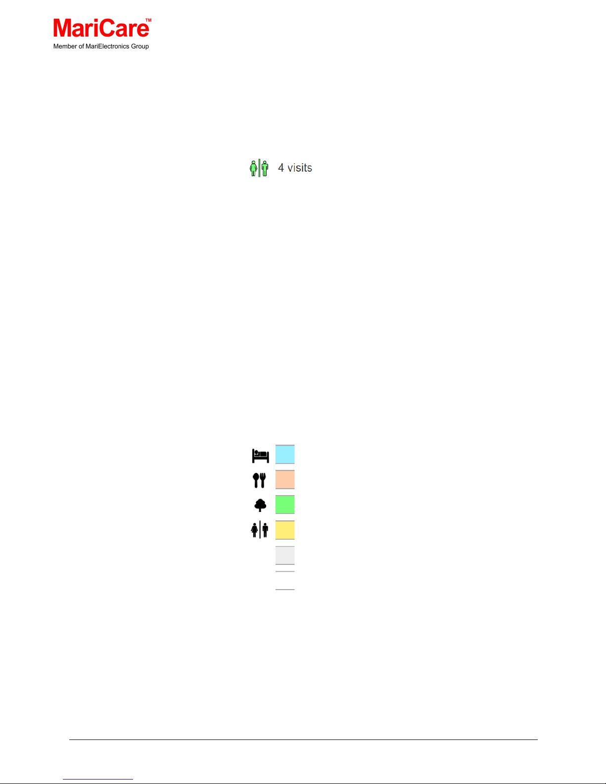
The toilet field tells the number of times the resident has visited the
toilet since the beginning of the day (00:00:00). In the example
below, the resident has visited the toilet 4 times.
The color of the icon is chosen according to the following rules:
No bathroom activity indicator => white
0 – 0.75 => green
0.75 – 1.0 => yellow
>= 1.0 => red
6.8 TIMELINE
The time line illustrates the movements of the resident. Each
location visited by the resident is shown as a colored bar whose
length corresponds to the time the resident spent in that
location. The colors and icons are as follows:
Bedroom.
Kitchen. The icon, if present, tells when the fridge
was opened.
Outdoors.
Bathroom.
Living room or entrance.
Other or unknown location.
The icon is visible when the length of the visit is > 30 min or the
location is bathroom or the icon is the meal icon.
Page 23
MariCare Oy, www.maricare.com 23 (32)
6.9 HISTORY
Clicking the down arrow reveals the time line for the last 7 days.
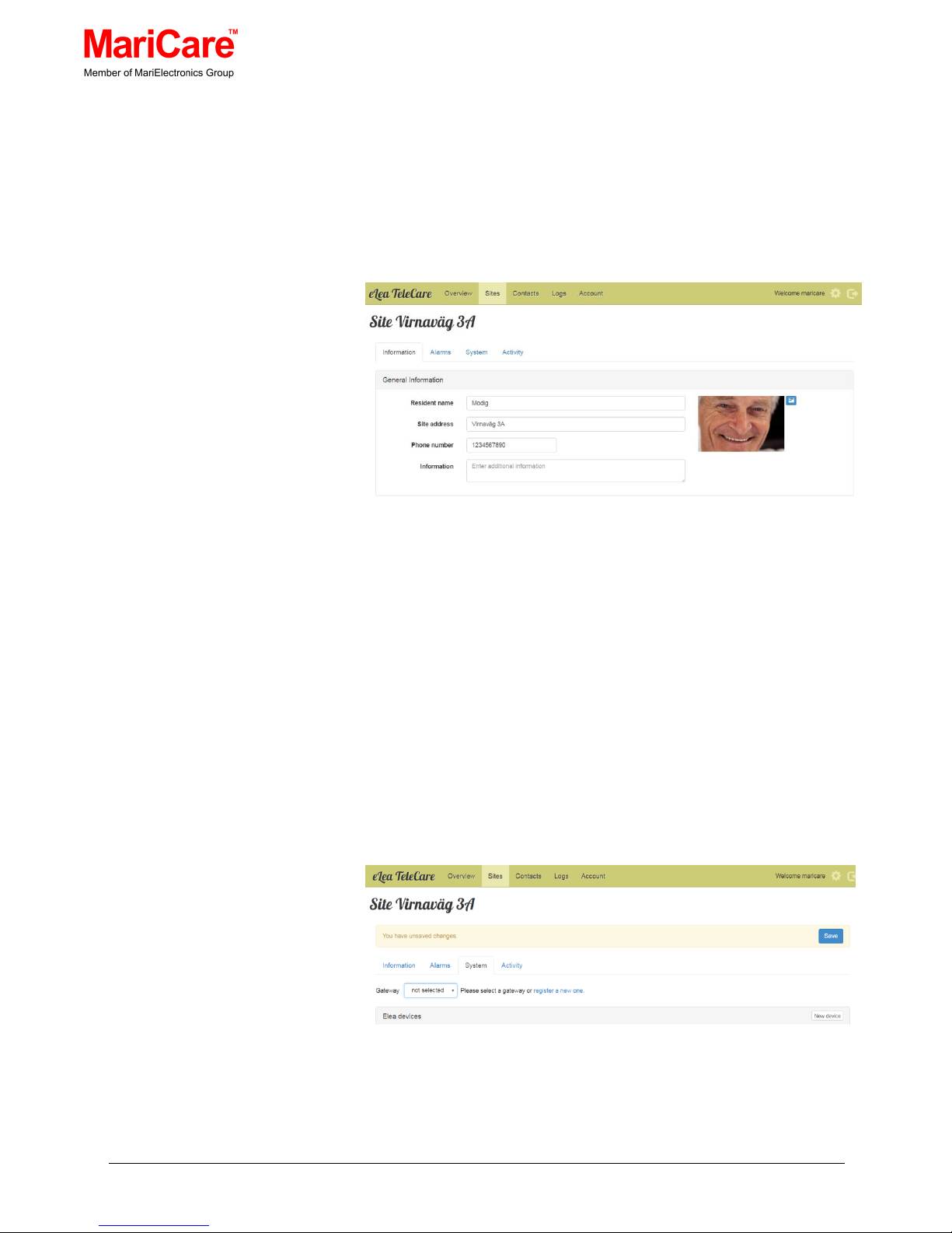
6.10 INFORMATION
Figure 6.6 Resident information
Resident’s detail info: name, site address, phone number and
additional information.
6.11 CREATING NEW SITE
After creating a user account, the user must go to the ‘Sites’ tab and
click ‘New site’, where the basic information for the site is entered.
What is absolutely essential is to click on the ‘System’ tab and select
a gateway from the dropdown list and press ‘Save’.
Figure 6.7 Select Gateway from List
Page 24
MariCare Oy, www.maricare.com 24 (32)
6.12 PAIRING EACH DEVICE WITH THE
SYSTEM’S GATEWAY
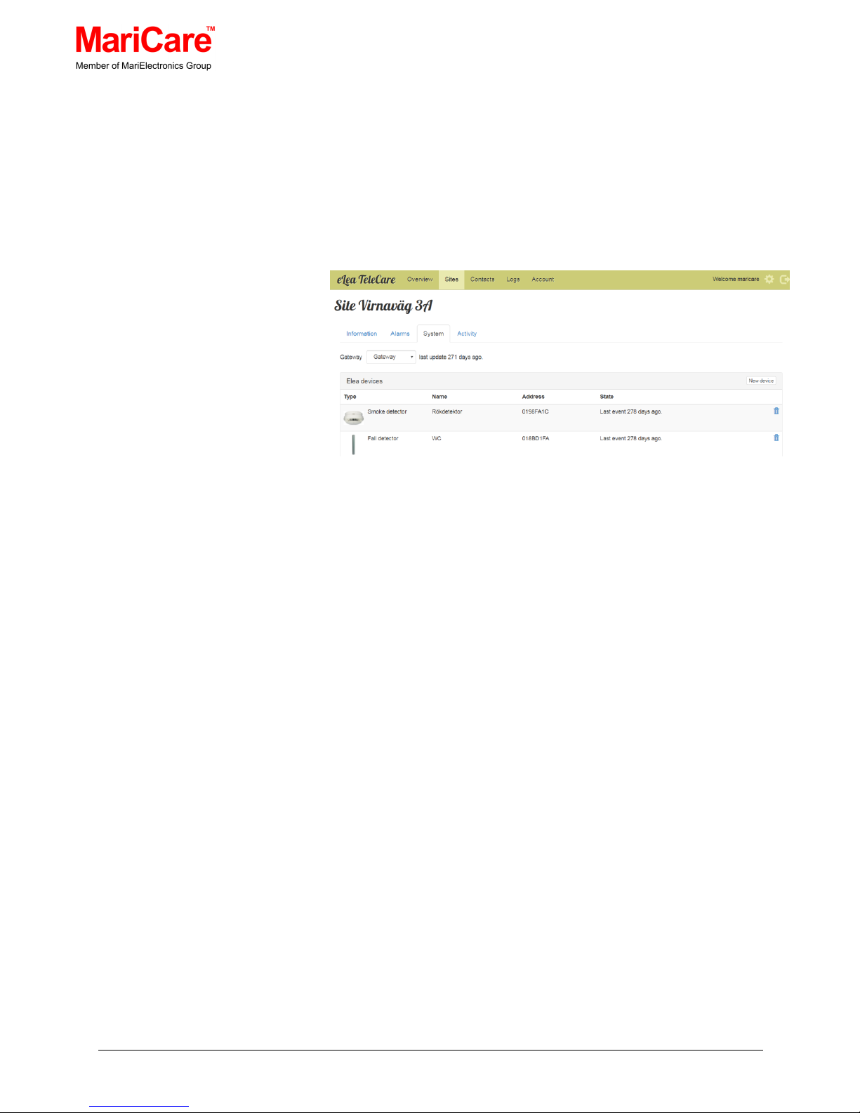
When the ‘Sites’ tab is clicked on the main window menu and then
the ‘System’ tab, a list of paired devices is displayed with th eir
information and status. Initially, this page is empty and the user must
add the devices.
Figure 6.8 Pairing the eLea™ System Devices
The ‘System’ page columns are
• Type:
This column shows the type of device with its accompanying icon
that is paired with the gateway
• Name:
This column shows the name of the device
• Address:
This column shows the address of the device. Each device has a
unique address.
• State:
This column shows the last time the server has gotten a message
from the device
To edit the information on the pairing of an eLea™ device with the
gateway, double click on the row containing the
e
Lea™ device’s
information. This will display the ‘Edit device’ dialogue window and
the information can be modified.
Page 25
MariCare Oy, www.maricare.com 25 (32)
Similarly, to add a
e
Lea™ device (i.e. pair a device with the
Gateway):
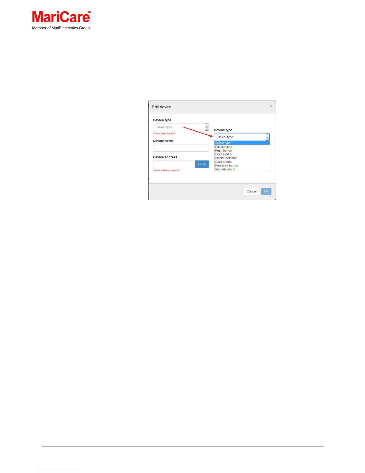
• Click on the ‘New device’ button, which will display an empty ‘Edit
device’ dialogue window
Figure 6.9 Edit (and Add) Device Dialogue Window
• Click on the ‘Device type’ field down-arrow and select the type of
device from the ‘Select type’ dropdown list
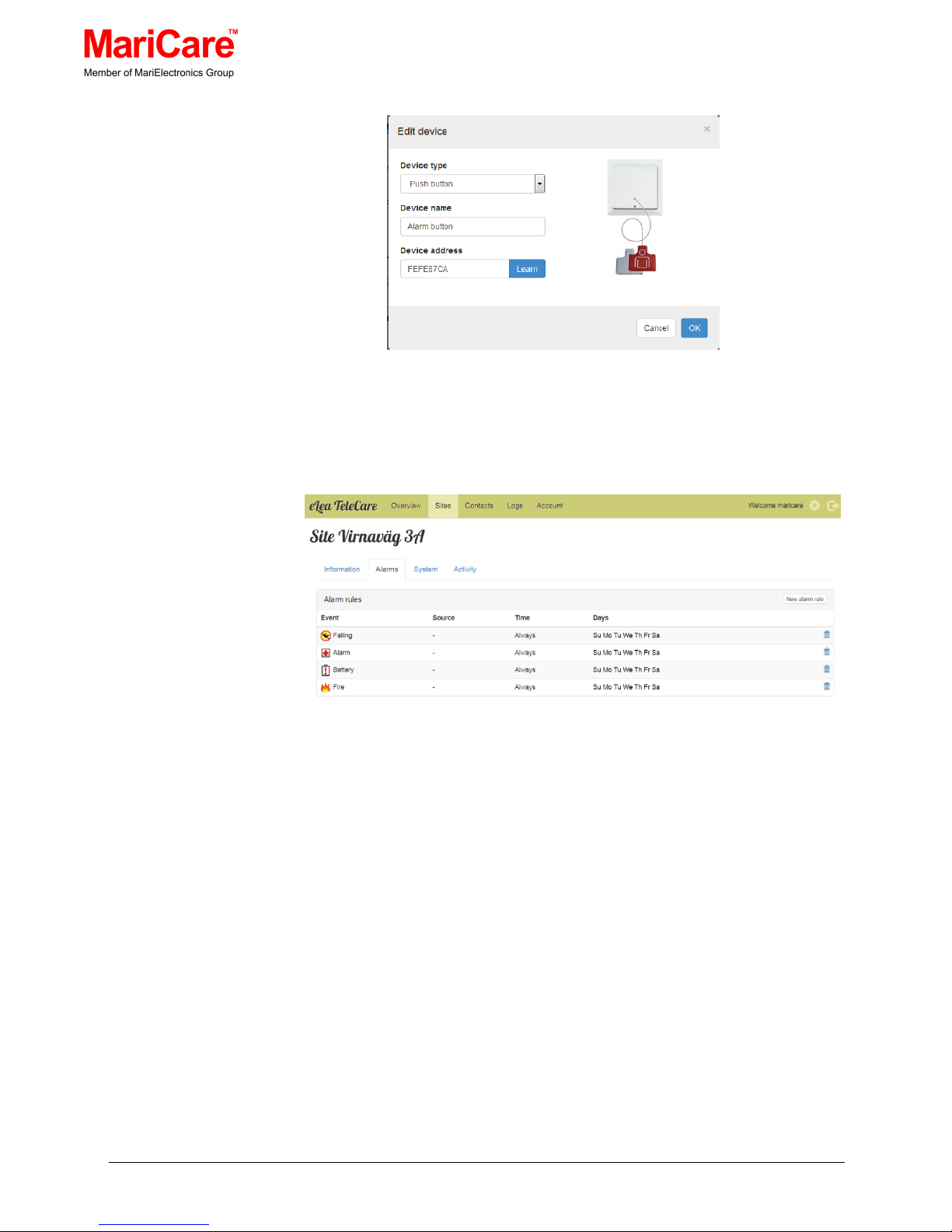
Note: When a device type is selected, the accompanying icon will
then be displayed on the ‘Elea devices’ list and also on the right
of the ‘Edit device’ dialogue window. See Figure 6.
• Type in the name of the device in the ‘Device name’ field
• Click on the ‘Learn’ button on the right of the ‘Device address’.
You must have the device you are adding at hand at this point.
Depending on the device, click on the Learn or Link switch on the
device you are adding. In case you are adding a simple switch,
press the switch once. A device address should appear on the
screen as in Figure 6..
• When the information is correct, click the ‘OK’ button
Page 26
MariCare Oy, www.maricare.com 26 (32)
Figure 6.10 Example of a Paired Device
6.13 CONFIGURING ALARM RULES
Figure 6.11 eLea™ System Alarms’ Information & Status
When the “Alarms” tab is clicked in the ‘Sites’ window, a list of alarms
with their information and status are displayed.
The ‘Alarms’ page columns are
• Events:
This column shows the event alarm with its accompanying icon.
See Figure 6.
• Source:
This column shows the name of the device from which the alarm
comes from or hyphen (-) for all devices.
• Time:
This column shows the period in the day when the alarm is active
Page 27
MariCare Oy, www.maricare.com 27 (32)
• Days:
This column shows on which days the alarm is active
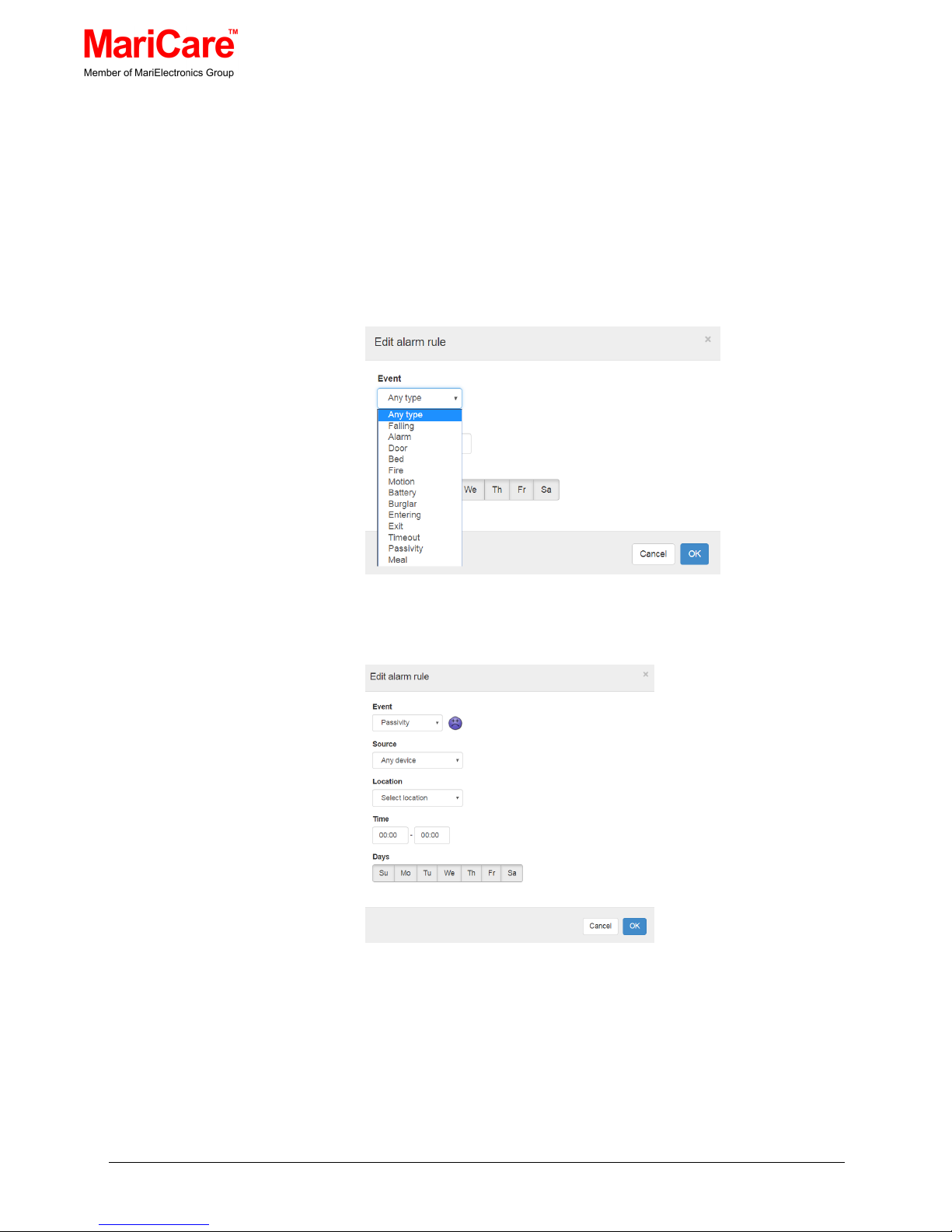
To edit an alarm rule, double click on the row containing the alarm
information, which will display the ‘Edit alarm rule’ dialogue window.
Similarly to add an alarm rule, click on the ‘New alarm rule’ button,
which will display an empty ‘Edit alarm rule’ dialogue window.
Figure 6.12 Edit Alarm Rule Dialogue Window
Figure 6.13 Edit Alarm Rule per source and/or location
To edit or add an alarm rule:
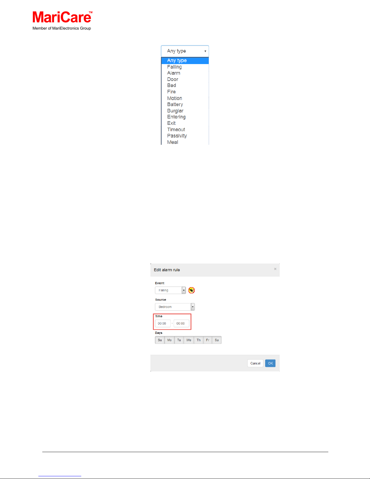
• Click on the ‘Event’ field down-arrow and select the type of
event from the dropdown list. See Figure 6..
Page 28
MariCare Oy, www.maricare.com 28 (32)
Figure 6.14 ‘Source’ Dropdown List
• Click on the ‘Source’ field down-arrow and select the name of
device from the dropdown list or select ‘Any device’. See figure
6.14.
• Type in the active time of the alarm in the ‘Time’ fields. By
default, the alarm is always active.
• Select the day or days the alarm is active by selecting the
day(s). By default the alarm is active every day.
• When the information is correct, click the ‘OK’ button
Figure 6.15 Example of an Alarm Rule
Page 29
MariCare Oy, www.maricare.com 29 (32)
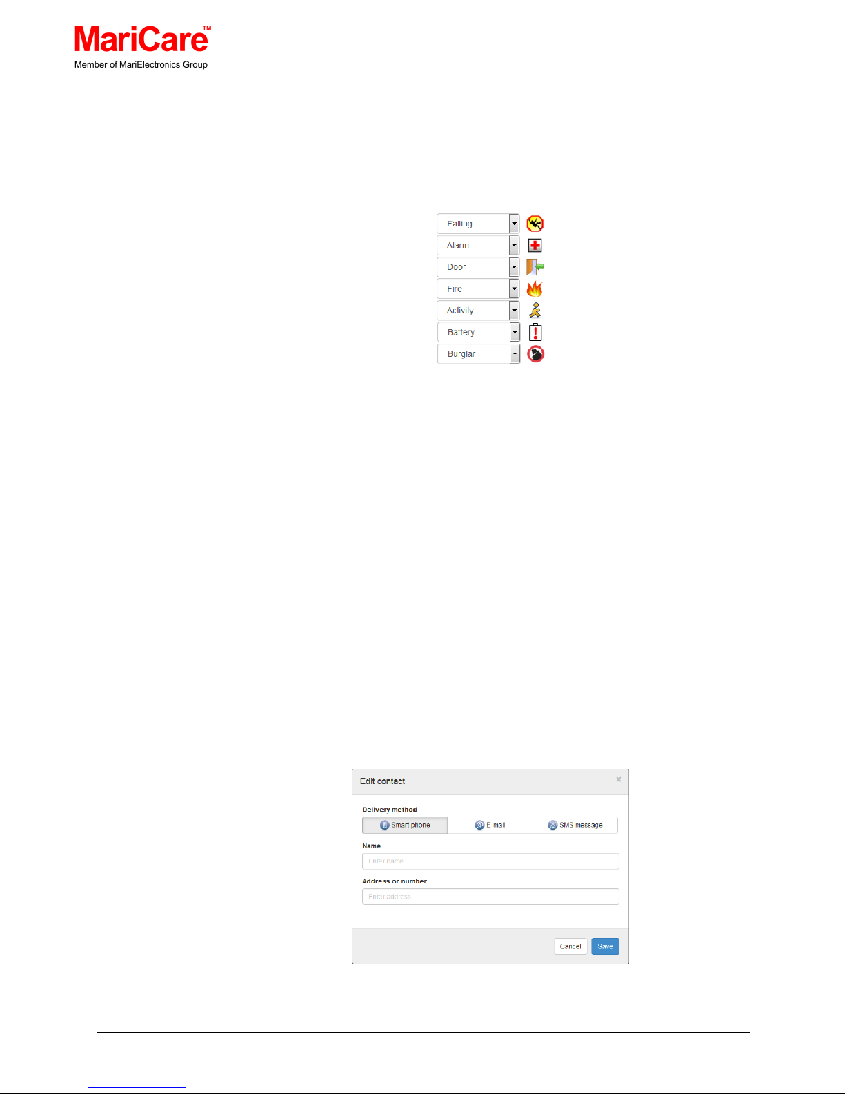
6.14 ALARM ICONS
To quickly catch the carer’s eye, each alarm is accompanied by a
colourful and distinctive icon.
Figure 6.16 Alarms with their Accompanying Icons
6.15 ALARM RECIPIENTS
When the ‘Contacts’ tab is clicked on the main window menu, a list of
alarm recipients (viz. carers that are on-call) and their information and
status are displayed. See Figure 6.5Figure 6.57
e
Lea™ System
Recipients’ Information & Status
To edit or add a recipient’s contact information:
• Double click on the row containing the recipient’s information,
which will display the ‘Edit contact’ dialogue window’
or
similarly, to add a recipient, click on the ‘New recipient’ button,
which will display an empty ‘Edit contact’ dialogue window.
Figure 6.17 Edit Contact Dialogue Window
Page 30
MariCare Oy, www.maricare.com 30 (32)
• In both cases, select the delivery method and fill out or modify
the Name and Address or Number fields.
• When the information is correct, click the ‘Save’ button
7. ACTIVITY INDICATORS
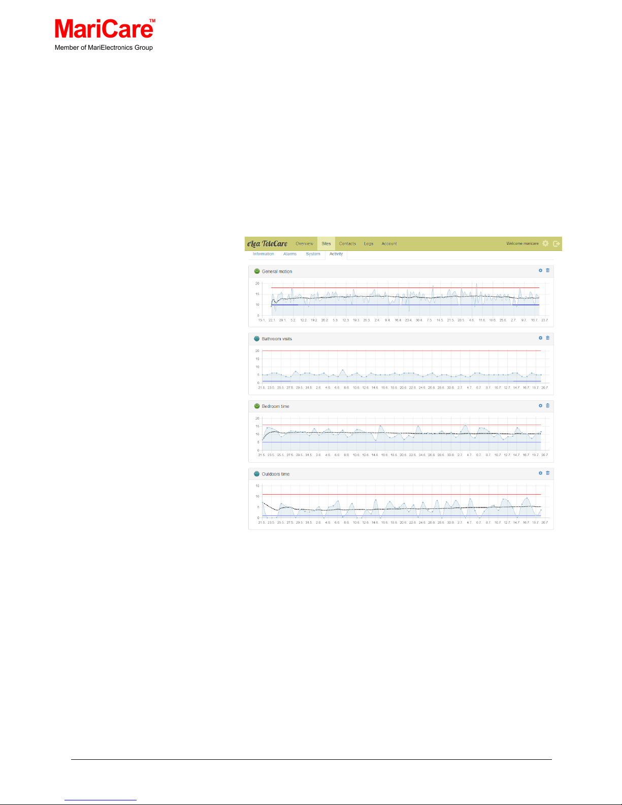
The activity tab allows the configuration of the activity indicators.
The system supports the following indicators:
• General motion
• Toilet visits
• Bedroom time
• Outdoors time
Each indicator can be configured with high and low limits. When
the value crosses these limits an activity alarm is triggered.
Each indicator is updated once per day at 12:00 (site local time).
Page 31

MariCare Oy, www.maricare.com 31 (32)
The graphs contain activity data from the last 2 months for toilet
visit, bedroom time and outdoors time indicators. The general
motion graph has data from the last 6 months.
General motion, bedroom time and outdoors time graphs have a
dotted moving average line computed from the last 30 days. The
high and low limits are specified in terms of percentiles of the
distribution of the values over the last 30 days.
Toilet visit limits are specified as absolute values.
8. APPENDICES
8.1 TYPES OF eLea™ SMART DETECTORS
• FD05R: Wireless with rechargeable battery
• FD05R9V: Wireless with replaceable 9V battery
• FD05CR: External power (cable), wireless transmission and no
battery
8.2 ABBREVIATIONS
PIR (Passive Infrared Sensor) is an electronic sensor that measures
infra-red (IR) light radiating from objects in its field of view. They are
most often used in PIR-based motion detectors.
PoE (Power over Ethernet) unit passes electrical power along with
data on Ethernet cabling.
RSSI (Received Signal Strength Indicator) is a common name for the
signal strength in wireless network environments. RSSI is a measure
of the power level that a radio frequency client device is receiving
from an access point.
DHCP (Dynamic Host Configuration Protocol) automatically provides
an Internet Protocol (IP) host with its IP address and other related
configuration information such as the subnet mask and default
gateway.
Page 32

MariCare Oy, www.maricare.com 32 (32)
MariCare™
P.O. Box 500 Virnatie 3
FI-01301 Vantaa, Finland
Tel. +358 207 508 670
Fax +358 207 508 501
Email: [email protected]
 Loading...