

MARIAN TRACE PRO AE User Manual

TRACE PRO AE
User’s Guide

© November 2006, v1.06 MARIAN.
Hardware Design by MARIAN
All rights reserved. No part of this User's Guid'e may be reproduced or transmitted in any form or by any
means, electronically or mechanically, including photocopy, translation, recording, or any information
storage and retrieval system, without permission in writing from MARIAN.
All trademarks are the property of the respective owners.
MARIAN is not liable for any damage to the software, hardware and data and costs resulting from it, which
are caused by improper handling or installation of the hardware. Technical changes are reserved.
Table of Contents
Welcome 4
Features 6
Installation 7
Scope of supply 7
System requirements 7
Connectors on the TRACE PRO AE 8
AES/EBU Inputs and Outputs 8
Wordclock/SuperClock Input 8
Analog Inputs and Outputs 8
S/PDIF Input 9
TDM SyncBus 9
The TRACE PRO AE in Detail 10
The first contact 10
The Mixer 11
What is it all about? 11
The channels 12
Specialities of digital channel strips 14
The master channel 14
Adaptable – changing the view of the TRACE PRO AE Mixer 15
The number of aux sums 16
Further functions 16
The Output Control 18
What is it all about? 19
Adaptable – changing the view of the Output Control 20
The clock status panel 22
What is it all about? 22
Clock-status and sample rate 22
Samplerate converter 23
Saving and loading setups 24
The MARIAN TDM SyncBus 26
Principles of the TDM SyncBus 26
Using the TDM SyncBus 26
The settings 28
Synchronization 29
Latency 33
Audio Options 34
ASIO Device Setup 36
The TRACE PRO AE in the connection with digital devices 38
Background 38
What is a clock? 38
The rules in the digital audio world 39
Important notes on TRACE PRO AE and digital clock. 39
The channel references 42
Playback line 42
Record line 42
PCI Bus Master Technology 43
Hands on the TRACE PRO AE 44
Sounding Good 44
Background 44
How to do it? 44
Setting up the latency 45
Background 45
Setting up the “DMA Latency” 46
Setting up the audio driver latency 47

In a Project Studio 48
Situation 48
Hardware routing 48
Software routing 48
Volume settings 49
Finalizing 49
The TRACE PRO AE as hard-disk-recording-system 50
Situation 50
What’s there to care about? 50
The TDM SyncBus – Example 1 52
The situation 52
The solution 52
The TDM SyncBus – Example 2 53
The situation 53
The solution 53
Glossary 54
Technical Facts 58
Service and Support 61
Warranty 61
Contact 61

Welcome
Congratulations and thank you very much that you decided in favour of a
MARIAN product. You have chosen an innovative and powerful sound
system, created according to your needs, the needs of our faithful
customers. We are proud to present to you: the TRACE PRO AE.
With this fine piece of high technology you are well equipped for the future
of digital audio signal processing. That is because the TRACE PRO AE is
not just simply a recording system with professional connections in crystalclear audio quality of 24 bit and 192 kHz – once installed it will upgrade
your computer to a most flexible digital audio workstation. It offers you
possibilities realized yet with expensive additional equipment only and
hardly ever within a computer. You can, e.g. mix input signals and
playback signals of a software without any delay on a comfortable mixer
surface.
Due to the high quality input sample rate converter of digital input of the
TRACE PRO AE you achieve a flexibility in handling different digital
audio data format unheard-of so far. Thanks to the unique Output Control
extensive routings of all digital and analog single- and mix-signals are set
up, saved and recalled in a jiffy – just like at a patchbay.
As the special feature, the TRACE PRO AE includes the all-new TDM
SyncBus. This amazing and mighty tool of digital signal processing is
integrated directly within the powerful DSP mixer. With the help of the
TDM SyncBus all available signals can easily be directed to the input of a
TRACE PRO AE or other Marian Soundcards with TDM SyncBus option,
and are available there like “real” physical input signals. The resulting
routing- and mix-capabilities are almost unlimited.
Please take your time to go through the next pages of this manual also.
Besides helpful explanations for the installation, it offers many valuable
hints on how to use the Mixer and the Output Control effectively and
profitably. If you run in on technical terms while reading, which are
unknown to you, the glossary at the end of this manual will helpfully serve
you for their clearance.
Now, we do wish you lots of success in working with the TRACE PRO
AE. We hope it will bring you just as much fun, as we had developing it.
Your MARIAN Team
4

5

Features
Your TRACE PRO AE comes with a lot of great functions. Here you can
find a small list of properties and capabilities.
9
PCI Busmaster card
9
Full duplex support and Multi-Client Support
9
2 analog, balanced in- and outputs with switchable reference level
9
Digital Stereo in- and output in AES/EBU format
9
Digital S/PDIF input for internal CD/DVD drives
9
High-quality samplerate converter for the digital input
9
24 bit / 192 kHz resolution
9
Complete balanced signal circuits for all connectors
9
20 channel DSP Mixer; FPGA based, 40 Bits Precision; latencyfree
9
Flexible and extensive mix-, monitor- and routing possibilities
9
DAT-marker support
9
MARIAN SyncBus compatible
9
MARIAN TDM SyncBus compatible
9
WordClock/SuperClock input with software switch able
termination
9
Synchronization as clock master (output of internal clock on
AES/EBU outputs or SyncBus)
9
Synchronization as clock slave (using external clock on
WordClock or digital input or SyncBus)
9
Highly-developed multi-client driver for Windows™ XP: MME,
ASIO 2.0, GSIF 2.0, WDM-Audio, DirectSound
6

Installation
On the quick start guide and in the interactive tutorial on the driver CD you
will find all important installation steps explained graphically. If you have
any further questions concerning the installation, please contact our support
service. At the end of this manual you will find the different ways of
contacting us.
Scope of supply
After opening the package of the TRACE PRO AE, please check if the
following components are included and undamaged.
9
1 x TRACE PRO AE PCI slot card
9
1 x XLR breakout cable for analog
9
1 x XLR breakout cable for digital
9
1 x connector cable for internal S/PDIF input
9
1 x CD-ROM with driver software
9
1 x CD-ROM with bundle software
9
this manual with quick installation guide
System requirements
For successful and orderly operation of the TRACE PRO AE, the following
basic requirements have to be met.
9
Intel Pentium-, or AMD CPU with at least 1 GHz clock and 256
MB RAM
9
Operating system Windows™ 2000, Windows™ XP Home or
Professional or Windows
9
Direct X 9b
9
One free PCI slot
™
2003 Server
7
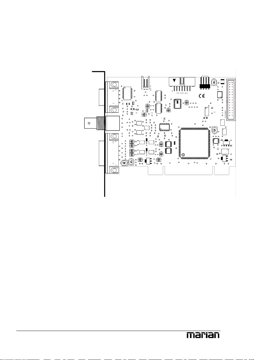
Connectors on the TRACE PRO AE
S/PDIF input for
internal CD/DVD
drives
AES/EBU breakout
cable connector for
digital in- and output
WordClock/Superclock
input
Breakout cable
connector for analog
in- and output
TDM
SyncBus
AES/EBU Inputs and Outputs
The stereo AES/EBU in- and output is connected to the TRACE PRO AE
using a breakout cable.
Wordclock/SuperClock Input
Connect the Wordclock or SuperClock output of a digital clock device
here, if the TRACE PRO AE is to be synchronized externally.
Analog Inputs and Outputs
The stereo analog in- and output is connected to the TRACE PRO AE using
a breakout cable.
8

S/PDIF Input
Connect the digital output of an internal CD or DVD drive. The signal is
available in the “Digital” input channel of the Mixer if “CD” is choosen in
the drop down list.
TDM SyncBus
If other MARIAN sound systems with TDM SyncBus option are installed,
they can be connected here using a TDM SyncBus cable. Other MARIAN
sound systems with SyncBus option only, can be connected using an
adapter cable. Both cables can be ordered at the MARIAN web shop.
9

The TRACE PRO AE in Detail
The first contact
After the successful installation the symbol of
the TRACE PRO AE manager appears in the
Windows™ taskbar of your computer. It offers
you direct access to important driver settings,
the clock status display, the DSP-based 20
channel Mixer and the Output Control of the
TRACE PRO AE. Furthermore, you can save
and load the setups for Mixer and Output
Control. Via “Visualizations” you may choose
the different skins for Mixer and Output
Control. “Info” shows the current driver
version of the TRACE PRO AE. This is
needed when consulting our support service
with certain questions. The menu is opened
with a single mouse click, with another on the
corresponding entry the window of it is being
opened. Via clicking the option “Always on
Top” it is prevented that any other window can
cover the Mixer or the Output Control. This
option is helpful, when working simultaneous
with other windows, while wanting constant
direct access on Mixer and Output Control.
Z
PRO AE have been
installed, the entries for
Mixer and Output Control
will appear accordingly
with the extension „#2“,
„#3“ and so on. The
settings of the sound
systems are managed via
one window.
If several TRACE
10
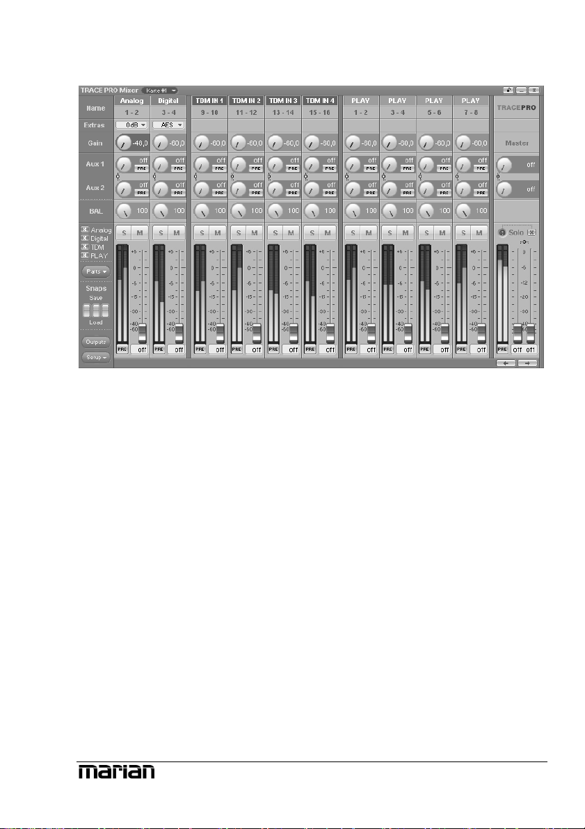
The Mixer
What is it all about?
This window shows all input channels and the master section of the
TRACE PRO AE Mixer. You can see physical inputs (analog and digital),
the channels of the TDM SyncBus (TDM In 1 to 4) and the playback
channels of an audio application. (Play 1-2 to 7-8) The TRACE PRO AE
offers an application with 16 playback channels as Play 1-2 to 15-16.
Within the mixer though, only Play 1-2 up to 7-8 are shown as separate
input channel strips. The Mixer treats all shown types of channel equally.
11
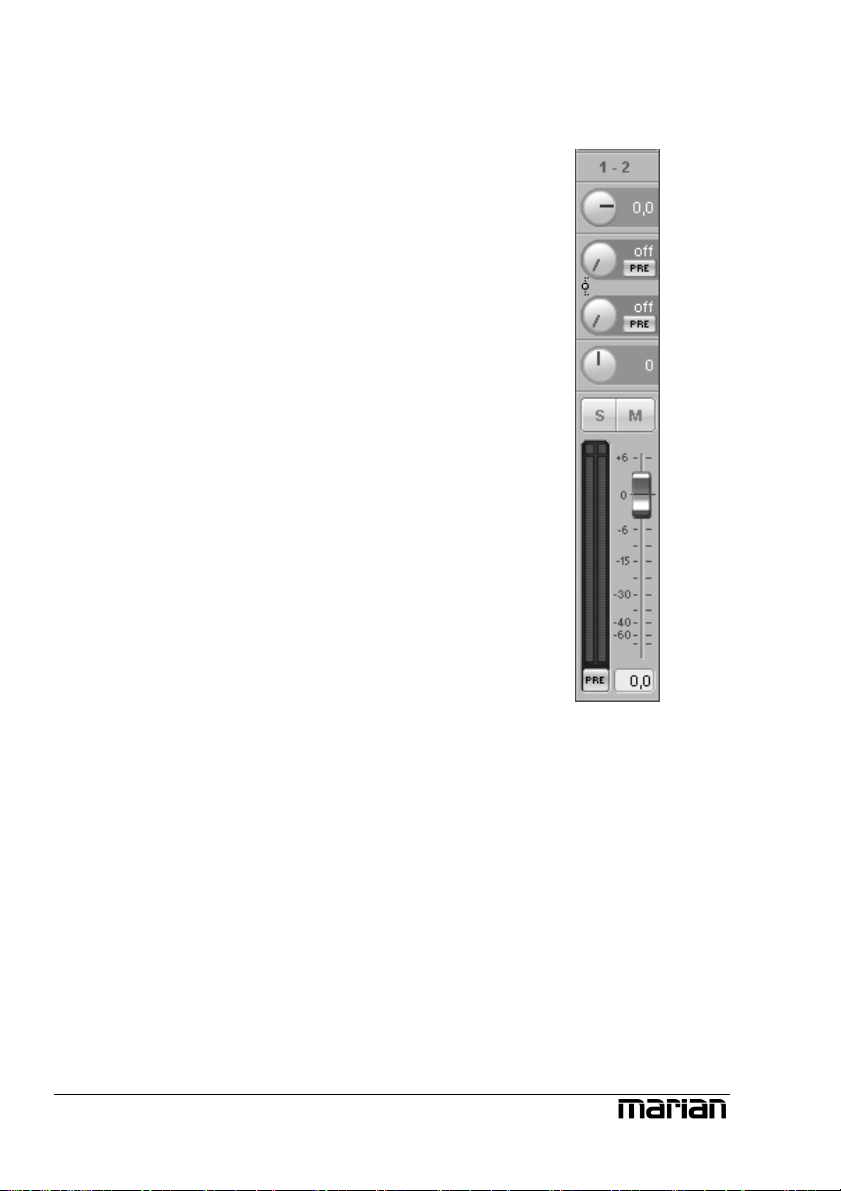
The channels
As an example for all types of channels, let’s
take a look at input channel “1-2” from top to
bottom.
First we have the “GAIN”-knob. It is for
adjusting the audio level. For the analog input
the level adjustement takes place directly at the
input stage of the TRACE PRO AE. This
influences the level with which a software
application is recording from this input. That is
why the “GAIN” knob of the analog input is
pictured in a different colour. Using the level
switch a level adjustment of the input stage can
be achived. This affects the range of the
“GAIN”-knob.
Beneath “GAIN”, “AUX 1”, “AUX 2” and so on
are placed. Pulling up knob “AUX 1” will result
in a volume increase of the signal in the signal
sum aux 1, pulling up knob “AUX 2” increases
the volume of the signal in signal sum aux 2 and
so forth. Hence the aux knobs have the same
function like the fader at the end of the channel,
except: not for the master sum, but for each aux
signal sum.
Besides the aux knobs the “PRE”-button is
located. If it is activated with a mouse click, the
fader at the end of the channel looses its
influence on the corresponding aux knob. Thus,
the fader can, for example, be placed on position
“-60” while still a signal reaches the Output
Control of the TRACE PRO AE via the affected
aux knob. Between “AUX 1” and “AUX 2” as
well as “AUX 3” and “AUX 4” and so on a linkbutton is situated. If clicked on, aux volume and
pre buttons for aux 1 and 2, aux 3 and 4 and so
on are connected functionally. That means: when
opening up “AUX 1”, “AUX 2” is equally pulled
up. Just like that, “PRE”-button of “AUX 2” is
12
Z Instructions on how to
monitor these aux sums
on the TRACE PRO AE,
you will find in section
“The Output Control”.
Z Examples on how to
use pre buttons and aux
sums correctly please
refer to the “hands on”part.
Z The number of shown
aux controls depends on
the operation mode of the
TRACE PRO AE!

Z If you set up different
volumes for “AUX 1”
and “AUX 2” without the
link-button activated, this
relation remains with the
link-button pushed.
activated when pushing “PRE”-button of
“AUX 1”.
Now the balance knob “BAL” follows. It
regulates the volume relation between left and
right channel of the signal, the way it shall
appear in the master sum.
Z The solo button has no
influence on the aux
sums!
Z Double clicking the
field next to the Pre
button allows you to enter
volumes numerically in
dB values.
If the “Solo”-button is active in one or more
channels, the mix out of the TRACE PRO AE
provides the signal of these channels only.
If the “Mute”-button is active in one or more
channels, the mix out of the TRACE PRO AE
and the affected aux sums do not carry these
signals. The aux busses of these channels are not
muted if their “PRE”-button is active.
With the help of the fader at the end of the
channel strip, the portion of volume of the
channel on the master sum is regulated. Next to
it, the level meter with clipping LED (up) and
“PRE”-button (down) are located.
If “PRE” is active, the level of the signal is
shown independently of the position or before
the gain knob. If “PRE” is not active, it is
measured and shown “post” – that means after
the fader. This applies to all channel types.
13

Specialities of digital channel strips
At the top of the channel “Digital In” a drop
down list ist placed. It allows choosing the signal
for this channel. It offers “AES” for the digital
AES/EBU input or “CD” for an internal
CD/DVD drive.
This ends our little overview on the input
channels of the TRACE PRO AE Mixer. Now,
you know how to set up the volume of a channel
on the master sum or the aux sums. The only
thing that’s missing is a possibility to control the
level of all of these sum signals. That’s what the
master channel on the right side of the Mixer is
all about.
The master channel
The upper knobs regulate the volume of the aux
sums. Between “AUX 1” and “AUX 2” as well
as “AUX 3” and “AUX 4” and so forth a linkbutton is situated. If clicked on, the concerning
Aux-knobs are connected functionally. That
means: when opening up “AUX 1”, “AUX 2” is
equally pulled up.
If the Solo-button has been switched on in any
channel, the master channel will indicate this
with a lit “Solo” LED. Using the “X”-button
next to “Solo” you can deactivate all solo
buttons of all channels simultaneously.
Z If you set up different
volumes for “AUX 1”
and “AUX 2” or the right
and the left fader without
the link-button activated,
this relation remains with
the link-button pushed.
The master faders serve as regulators for the
volume of the main sum. They are assigned
either to the left or the right channel. As long as
link-button is pushed, they are moved
synchronously.
14
Note: Hidden channels
Z
are still active, just like
they were shown.
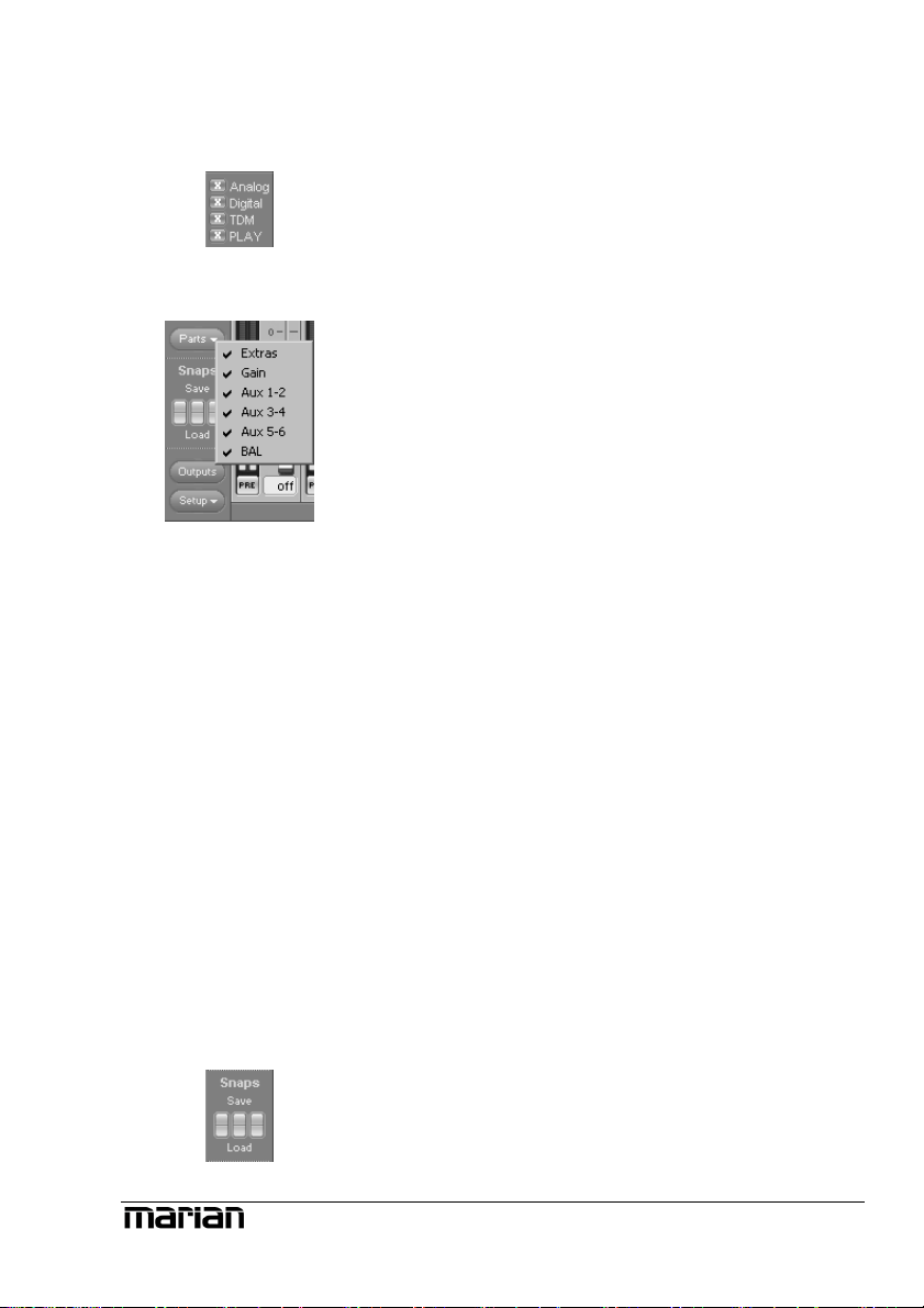
Adaptable – changing the view of the TRACE PRO AE Mixer
In the bottom left corner of the Mixer you can
find four buttons for “Analog”, “Digital”,
“TDM” and “PLAY”. These allow, with a click
on the button, to hide or show the affected
channels.
In order to adjust the look of the Mixer
according to your needs, single rows of control
elements can be hid or shown with the help of
“Parts”. This applies to all gain-, aux- or bal
knobs and the “Extra” row.
All these functions can be very handy for saving
precious space on your computer screen. But
they’re also useful if you wish to secure certain
setups of faders or knobs from accidentally
being changed.
Of course, apart from all these functions, the
window can be sized horizontally.
If multiple TRACE PRO AE have been
installed, you can bring up the Mixer of every
sound system using the drop-down list in the top
bar of the window. The lock-symbol in the upper
right corner of the window prevents coverage by
other windows. This way the Mixer is always on
top and accessible.
Z
independent of setups
(see chapter “Saving and
loading Setups”). Thus,
they will not be
overwritten by a setup.
Snapshots are
Yyou may save certain visual configurations
along with the current mixer settings in a
“snapshot”. For this, click on one of the three
buttons beneath “snaps” on the row “save”. If
ou wish to recall a snapshot, click on the
“load”-button situated beneath the previously
saved snapshot.
15
The number of aux sums
The TRACE PRO AE can be operated in 3
different modes. Depending on the mode, only a
limited number of aux-sums will be available.
On samplerates up to 48 kHz 6 aux-sums will be
available. On 96 kHz there will be 2 aux-sums.
On 192 kHz, no aux-sum will be available.
That’s why the drop-down list of Mixer and
Output Control will be automatically adjusted
accordingly.
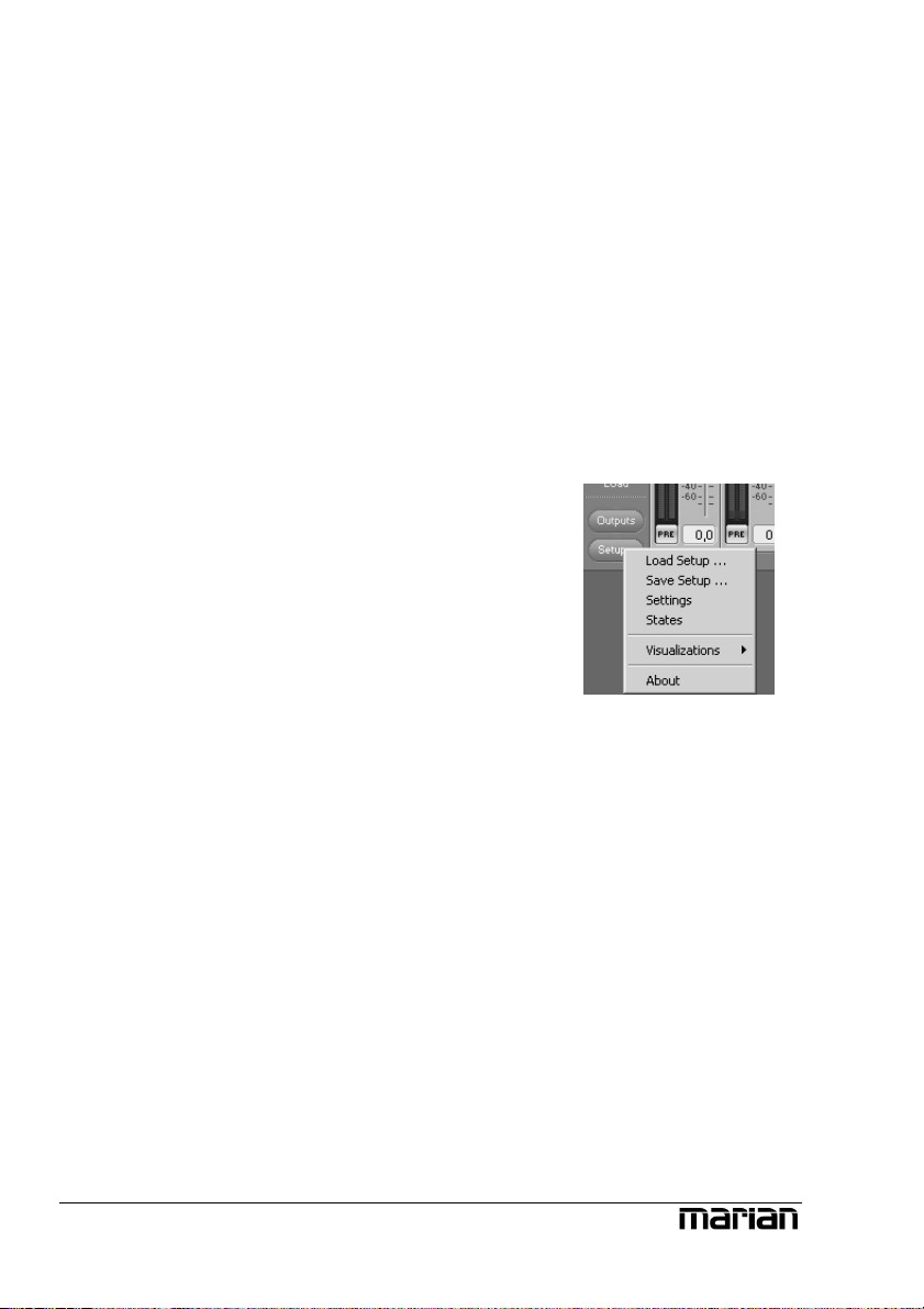
Further functions
In the lower left corner of the Mixer 2 function
buttons can be found. Via “Setup” the same
context menu is opened as when clicking on the
TRACE PRO AE symbol in the task bar. Here
you will find fast access to important functions
and windows of the TRACE PRO AE sound
system.
“Outputs” opens the Output Control. There again
you can quickly switch to the mixer surface
using the “Mixer” button.
Z
In section “The
TRACE PRO AE
settings” you get to know,
how to switch between
the modes and what the
outcome will be.
16

17
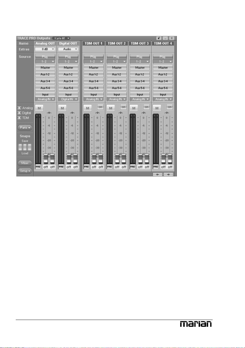
The Output Control
So far, we have taken a look at signals, which either entered the TRACE
PRO AE via a physical input or as a playback signal of a software.
The Output Control allows controlling all signals, leaving the TRACE PRO
AE. It is opened with single click on “Output Control” via e.g. the TRACE
PRO AE symbol on the Windows™ taskbar.
You probably figure, that this window looks pretty much like the Mixer
window. Sure it doesn’t have gain-, aux and bal knobs but it has routing
buttons instead.
18
 Loading...