

Margus H.264 Operation Instruction Manual

H.264
Digital Video Recorder
Operation Instruction

Page 2 of 49
Statement:
Copyright ©2010
Any extraction, reproduction or distribution of this manual in part or in
whole by any company or any individual is prohibited without written consent
of our company.
The content of this manual will be updated at any time without notice as a
result of product version upgrade or other reasons. Except otherwise specified,
this manual is only used for application guidance, and all descriptions,
information and recommendation in this manual will not constitute any
expressed or implied warranty.

Page 3 of 49
Precautions:
1. This video recorder is powered by utility power through DC12V adapter, please
check the power supply of power socket to see if it meets the requirement of the
adapter before installation is carried out;
2. Never place the video recorder at humid place or place subject to rain;
3. The video recorder should be installed at a place without strong vibration;
4. The video recorder should be installed at a place without direct sunlight and far
away from heat source and high temperature;
5. When the video recorder is installed, its rear panel should be more than 15cm away
from other object or wall to facilitate heat emission by fan;
6. Allow the video recorder to work within the temperature, humidity, and voltage
ranges permitted by the technical criteria;
7. Never store chemicals from which corrosive and volatile gas may be created in the
place where the video recorder is installed, lest the service life of video recorder will
be affected;
8. The video recorder should not installed where there are many dusts, and the
surrounding environment should be kept clean;
9. When the video recorder is used, correct grounding should be ensured;
10. When the video recorder is installed, correct connection to other devices should be
ensured;
11. Please purchase hard disk from formal channel, so as to suit long term, mass data
read-write requirement of DVR;

Page 4 of 49
Contents
Chapter I: Introduction .................................................................................................................... 6
1.1 Main features ........................................................................................................................ 6
1.2 Product features ................................................................................................................... 6
1.1.1 Performance parameters ........................................................................................... 6
1.1.2 Basic working parameters ........................................................................................ 8
Chapter II: Environmental adaptation ............................................................................................. 8
Chapter III: Operation manual of main frame ................................................................................. 9
3.1 Remote control ..................................................................................................................... 9
3.2 Mouse operation ................................................................................................................. 10
3.3 System operation ............................................................................................................... 11
3.3.1 User login ........................................................................................................................ 11
3.3.2 Menu operation ............................................................................................................... 12
3.3.3 Record setting ................................................................................................................. 12
3.3.4 Site setting ...................................................................................................................... 13
3.3.5 Network setting ............................................................................................................... 16
3.3.6 Alarm setting ................................................................................................................... 20
3.3.7 PTZ control ...................................................................................................................... 22
3.3.8 Hard disk management ................................................................................................... 23
3.3.9 Record backup ................................................................................................................ 23
3.4 System setting ........................................................................................................................ 24
3.5 Preview ................................................................................................................................... 27
3.5.1 Record control ................................................................................................................. 27
3.5.2 Record playback ............................................................................................................. 28
3.5.3 PTZ operation ................................................................................................................. 30
Chapter IV: IE operation manual .................................................................................................. 31
4.1 Functional characteristics .................................................................................................. 31
4.2 Constraint condition ........................................................................................................... 31
4.3 User login ........................................................................................................................... 31
4.4 Interface operation ............................................................................................................. 32
4.4.1 Remote setting ................................................................................................................ 32
4.4.2 Local playback ................................................................................................................ 33
4.4.3 Remote playback ............................................................................................................ 34
4.4.4 Preview configuration switching ...................................................................................... 35
4.4.5 Listening .......................................................................................................................... 35
4.4.6 Snapshot ......................................................................................................................... 35
4.4.7 Log .................................................................................................................................. 35
4.4.8 Group management setting ............................................................................................ 36
4.4.9 Working hard disk ........................................................................................................... 37
4.4.10 Group management switch ........................................................................................... 37
4.4.11 Preview channel setting ................................................................................................ 37
4.4.12 Record ........................................................................................................................... 38
4.4.13 PTZ control .................................................................................................................... 38
Chapter V: DVR installation guidance .......................................................................................... 39
5.1 Definition for interfaces of front and rear panels .................................................................. 39
5.1.1 Definition for interfaces of front panel ............................................................................. 39
5.1.2 Definition for interfaces of rear panel .............................................................................. 40
5.2 Alarm post interface ............................................................................................................. 40
5.2.1 Alarm input & output ....................................................................................................... 41
5.2.2 Wiring diagram of alarm output ....................................................................................... 41
5.3 System networking example diagram: ................................................................................. 42
5.4 Hard disk installation ............................................................................................................ 42
Chapter VI: FAQ ........................................................................................................................... 45

Page 5 of 49
Introduction
This manual describes a 4/8 channel embedded digital video recorder and its detailed specifications,
details the functions and application precautions for each module of the device, as well as the definitions
for the signals of each connector on the rear panel.
Chapter I Introduction. Product functions and main features are briefly introduced.
Chapter II Environmental adaptation
Chapter III Operation manual of main frame. Including functional introduction for the press keys of
remote control, and the operation function corresponding to each menu interface and the
meaning of each option setting are explained in details.
Chapter IV Remote monitoring software. The operation function corresponding to each IE menu
interface and the meaning of each option setting are explained in details.
Chapter V DVR installation guidance. Signal arrangement and connectors of rear panel are detailed;
the definition for the signal of each external cable; the definition of front panel and the definition
of each interface are also detailed.
Chapter VI FAQ.

Page 6 of 49
Chapter I: Introduction
1.1 Main features
This DVR series is a 4/8 channel real time CIF high resolution digital video recorder. It features real
time monitoring, local recording, playback, supporting 3-bit-stream remote network monitoring, data
backup, parameter setting, supporting motion detection alarm, supporting USB mouse etc functions.
1.2 Product features
Video compression format is standard H.264
Two USB interfaces, 2 for data backup, 1 for mouse operation
16-bit true color translucent graphic menu interface, menu option notation prompt
4/8 channel synchronous playback
Two-stage user authority management
Support multi-picture real time browse, parameter setting, backup or record playback to
local device by network.
1.1.1 Performance parameters
Type
4 4 8
Compression
standard
H.264
Picture input
1.0Vp-p/75Ω, BNC×4
1.0Vp-p/75Ω, BNC×4
1.0Vp-p/75Ω, BNC×8
Picture output
1.0Vp-p/75Ω, BNC×1; VGA×1
Resolution
Preview: D1
Record: full CIF full real
time or full D1 non-real
time
Preview: D1
Record: 1D1+3CIF full real
time or full D1 non-real
time
Preview: D1
Record: full CIF full real
time, or full D1 non-real
time
Frame rate
PAL : 100 Fps(CIF)
NTSC : 120 Fps(CIF)
PAL : 200 Fps(CIF)
NTSC : 240 Fps(CIF)
Audio input
RCA×1
RCA×4
Audio output
RCA×1
Audio codec
ADPCM
Record mode
Manual record, scheduled record, motion detection record and external alarm record
Simplex/duplex
/triplex
Triplex (record, playback, network transmission)
Network interface
RJ45 (10M/100M self-adapting)
PTZ control
None
Support

Page 7 of 49
Communication
interface
RS485×1,USB2.0×2
Number of
hard disk
1 SATA hard disk (up to
2T)
2 SATA hard disk (up to 2T for single hard disk)
Mouse
USB mouse
Remote
control
Optional
Yes
Power supply
12V/3A
Appearance
description
DVR-16 appearance
DVR-22 appearance

Page 8 of 49
1.1.2 Basic working parameters
Item
Working
parameters
Description
Input voltage
12V
DC 12V.
Video input
impedance
75Ω
The video input impedance of each channel is 75Ω.
Video output
1Vp-p
Output one 1Vp-p CVBS analog signal.
SATA interface
of hard disk
Two SATA interfaces, support SATA hard disk with mainstream
capacity
Working
temperature
-10----50℃
It is environmental temperature under good ventilation condition.
I/O interface
0—2V
It is low level alarm.
5V-30v
It is high level alarm.
RS485 serial
port
Support PTZ protocol Pelco-D, Pelco-P
Chapter II: Environmental adaptation
In order to ensure safe application of DVR and obtain satisfactory service performance, prolong the
service life of device, customer should fully consider the following factors when install the device:
1) When the device is installed and operated, all specifications of electronic product and the
requirements of vehicle and other connecting device should be followed;
2) Power supply and grounding:
Never use wet hand to touch power supply and video recorder.
Never drop liquid on video recorder, otherwise short circuit inside device or fire may be resulted.
Never pile other object on video recorder.
Use soft dry cloth to clean video recorder, never use chemical solvents.
After the power cable of video recorder is connected to power socket, there is still voltage inside
the device even if the video recorder has not been started.
If the device is not to be used for long term, it is preferred to fully disconnect the power supply of
video recorder, and unplug the power cable from the power socket.

Page 9 of 49
Chapter III: Operation manual of main frame
In the operation of this device, the Enter key on remote control has the same
function as the left click of mouse.
3.1 Remote control
Remote control is a minor input device to browse system interface.
The function keys of remote control:
For single remote control operating multiple DVRS, please refer to
3.4.
No.
English name
Operation description
No.
English name
Operation description
1
【Power】
Power ON/OFF
9
【ENTER】
Confirm operation
Switch edit area (time, date, IP
address etc)
In preview state, switch between
full screen/multi-window
Enter select state of list box,
confirm list selection
Select/deselect check box
2
【DEV】
Device selection
3
【MENU】
Enter into main menu
10
【MUTE】
Mute enabled/disenabled
4
【ESC】
Close soft keyboard
Close current window
Exit current control
Return to previous menu
Exit select state of list box
In preview state, enter/exit PTZ control
5
【 】
Slow playback, 1/2×, 1/4×, 1/8×,
single frame play
11
【LENS/VOL-】
Lens control, volume reducing,
number decreasing
【 】
Fast playback, 2×, 4×, 8× playback
12
【LENS/VOL+】
Lens control, volume increasing,
number increasing
【 】
Stop play
13
【0~9 10+】
Number input preview state, zoom
in corresponding channel in full
screen
【 】
Start play in search state, play/pause
14
【FN】
Pop up control
【 】
Full screen/multi-window playback
mode switching
15
【 】
1/4/8/9 preview window mode
switching
6
【REC】
Record control
16
【PTZ】
Enter into PTZ control interface
7
【SEARCH】
Open search in playback interface,
long press for 5 seconds to switch
between VGA and monitor output.
Page 10 of 49
3.2 Mouse operation
Mouse is the main input device to browse system menu.
Note: except stated otherwise, all system functions in this manual are described by using mouse input
operation.
Mouse application of this system:
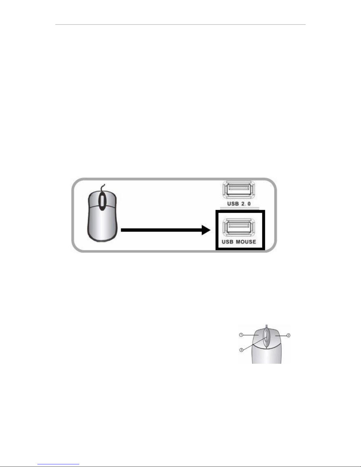
1)Insert USB mouse to the USB mouse port on the front panel of this system or the USB interface at
the bottom of rear panel.
Note: only the USB port at the top of rear panel is specially used for data backup by U-disk. Never
insert U-disk on the bottom USB interface of rear panel. When there is a USB interface on the front panel,
never connect USB deice here while the bottom USB interface of rear panel has USB device connected;
otherwise, only one device can be detected.
Figure 1.0 connect USB mouse to the bottom USB port of rear panel
2)The operation of mouse key is as follow:
·Left key: single click left mouse key on the functional menu option icon to enter the setting page
of the menu; double click left mouse key in real time monitoring picture or playback picture will
zoom in the image of certain channel, double click left key again to return to the monitoring and
playback of multi-channel picture.
·Right key: in real time preview picture, single click right mouse
key to enter the main menu of system. In menu page, single click
right mouse key to return to previous page.
3)Roller in the middle of mouse: no function at all.
Figure 1.1 Mouse key operation
Page 11 of 49
3.3 System operation
3.3.1 User login
1. Start the system
Power ON/OFF:
Connect power cable to the DC12V port on the rear panel of this system. When the system is started,
it will execute a basic system inspection and run initial load sequence. After few minutes, the system will
load real time display diagram.
Password
Note: in default condition, password is disabled in system. When you enter any system menu, no
password is required. But, for the sake of safety, we strongly recommend you to use password menu to
enable and set the password of the system.
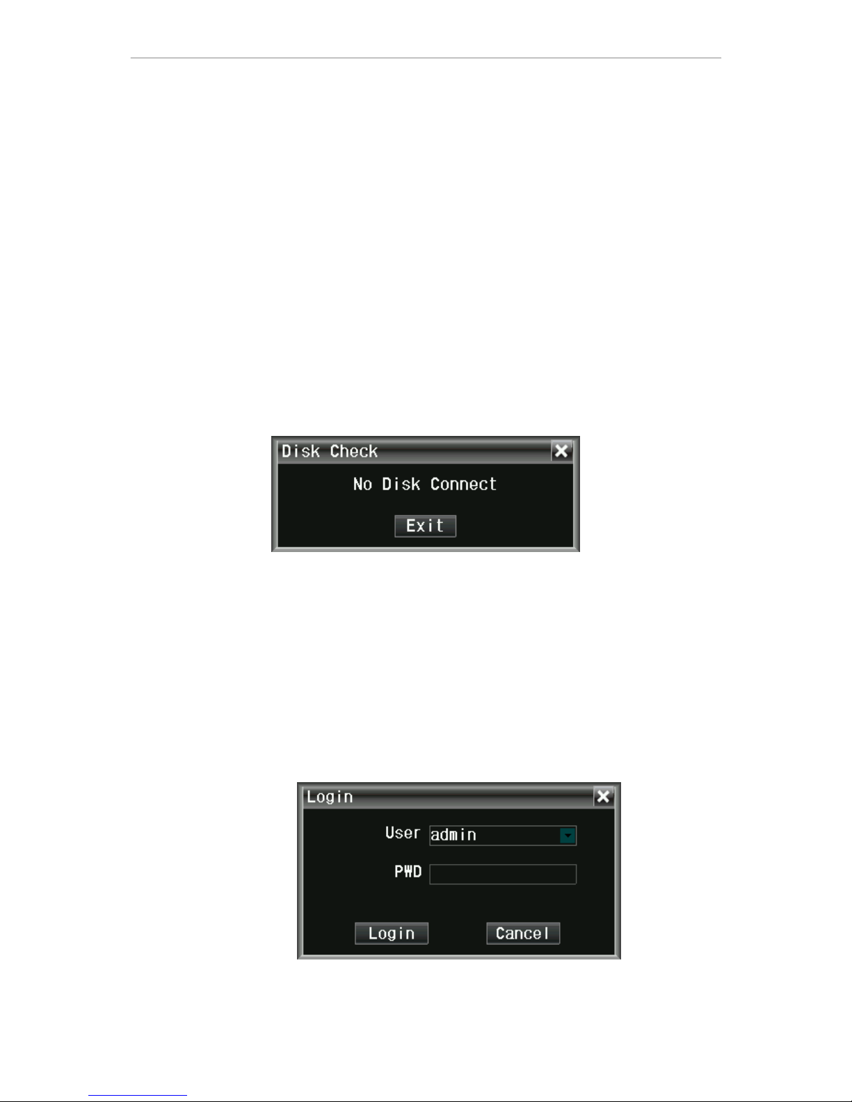
Note:
1)When the main frame is powered on, if no hard disk is installed on the device, or the installed
hard disk is not detected during starting up, or the installed hard disk hasn’t been formatted on
the local device, then the following dialog box will be displayed on video preview picture after
starting up.
2)Newly installed hard disk can be used normally only after being formatted through local device.
New hard disk can be detected automatically during starting up and it will prompt you to format
hard disk; if it is required to format hard disk in the system, the procedure is as follow: main
menu>hard management>format hard disk or right key shortcut menu>system information>hard
disk management
2. System login
Open main menu:
Single click right key on any position of screen, and select main menu (mouse operation), or press
menu/exit button on remote control or front panel of system.
Note: if password is enabled in the system, you need to select your user name, and input 6-digit
numeric password, so as to open main menu.
User: user can select authorized user name in user check box.
Password: input the corresponding password of the user name.

Page 12 of 49
3.3.2 Menu operation
The main menu includes『Record setting』,『Site setting』,『Network setting』,『Alarm setting』,『PTZ
control』and『Hard disk management』,『Record backup』,『System setting』items, as shown below:
Prompt: the settings to all submenus below are valid only after【Save】is pressed; the settings are
invalid when you exit this page directly without pressing Save.
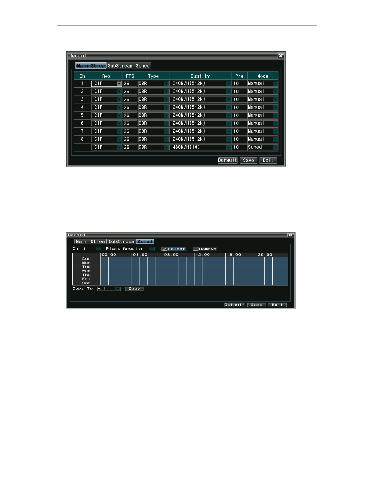
3.3.3 Record setting
Move cursor to『Record setting』item (glass framed icon means selected), press【OK】key to enter the
setting interface of the item, record setting includes main stream – sub stream – schedule, as shown
below:
The setting page of main stream is described as follow:
Resolution: D1-HD1-CIF optional
Frame rate: 2-25 frames optional
Coding: fixed stream and variable stream optional
Picture quality: 5 steps adjustable
Prerecording: set the length of prerecording time before alarm occurs
Mode: schedule record, manual record, close record optional
Prompt: when encoding is set as fixed stream, picture quality options are:
30M/H(64K)-60M/H(128K)-120M/H(256K)-240M/H(512K)-480M/H(1M)
When encoding is set as variable stream, picture quality options are: general – acceptable
– good – very good – best
Page 13 of 49
The setting page of sub stream is described as follow:
Resolution: CIF-QCIF optional
Frame rate: 2-5 frames optional
Coding: fixed stream and variable stream optional
Picture quality: 4 steps optional
Prompt: when encoding is set as fixed stream, picture quality options are:
30M/H(64K)-60M/H(128K)-120M/H(256K)-240M/H(512K)
When encoding is set as variable stream, picture quality options are: general – acceptable
– good – very good
The setting page of schedule is described as follow:
Channel: select the channel to be set
Schedule type: timing record, video alarm, external alarm optional
Select-remove: select means schedule record is enabled. Remove means schedule record is disabled.
Copy to: select the channel(s) to be copied to
Copy: execute the copy parameter
Prompt: black pane means the record schedule type has no function, blue pane means it has
function.
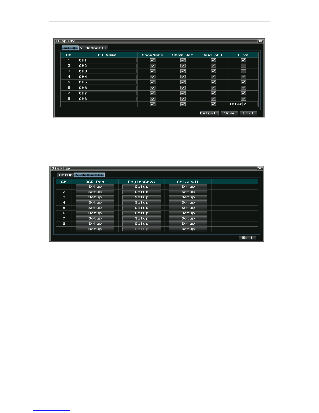
3.3.4 Site setting
Move cursor to『Site setting』icon item (glass framed icon means selected), press【OK】key to enter
the setting interface of the item, site setting includes basic parameter – video parameter, as shown below:
Page 14 of 49
The page of basic parameter is described as follow:
Channel name: set channel name
Display name: whether name is displayed in preview
Record state: whether record state icon is displayed in preview
Audio channel: bind audio channel number with this channel
Preview patrol: set the channel to be added to preview patrol
Prompt: the time interval of preview patrol is in second
The page of video parameter is described as follow:
Character overlapping: adjust the positions of channel name and timestamp on video image, as shown
below:
Page 15 of 49
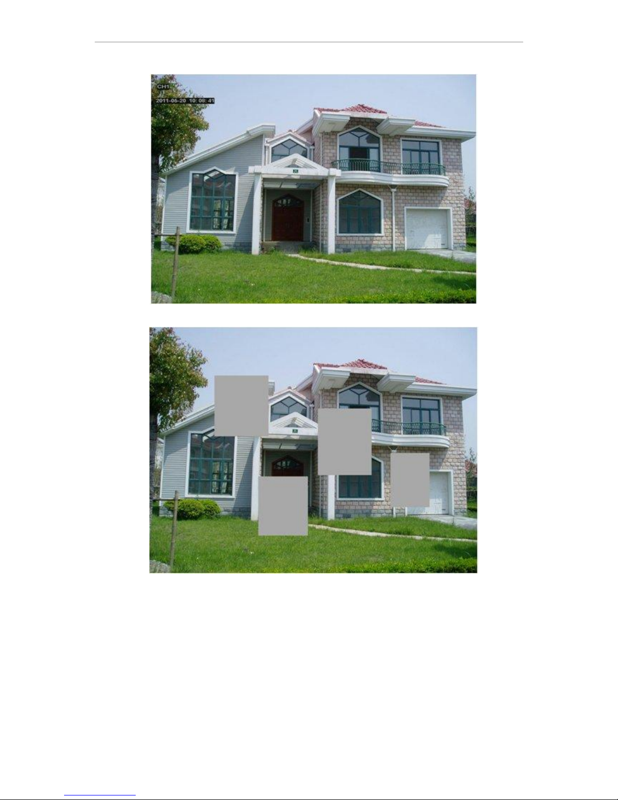
Zone coverage: user can mask certain zones in the picture; up to 4 zones can be set, as shown below:
Prompt: up to 4 zones can be masked in zone coverage
Image color: adjust the brightness, chromaticity, saturation and contrast of channel; click “Default”
button to restore to default setting
 Loading...