

Page 1
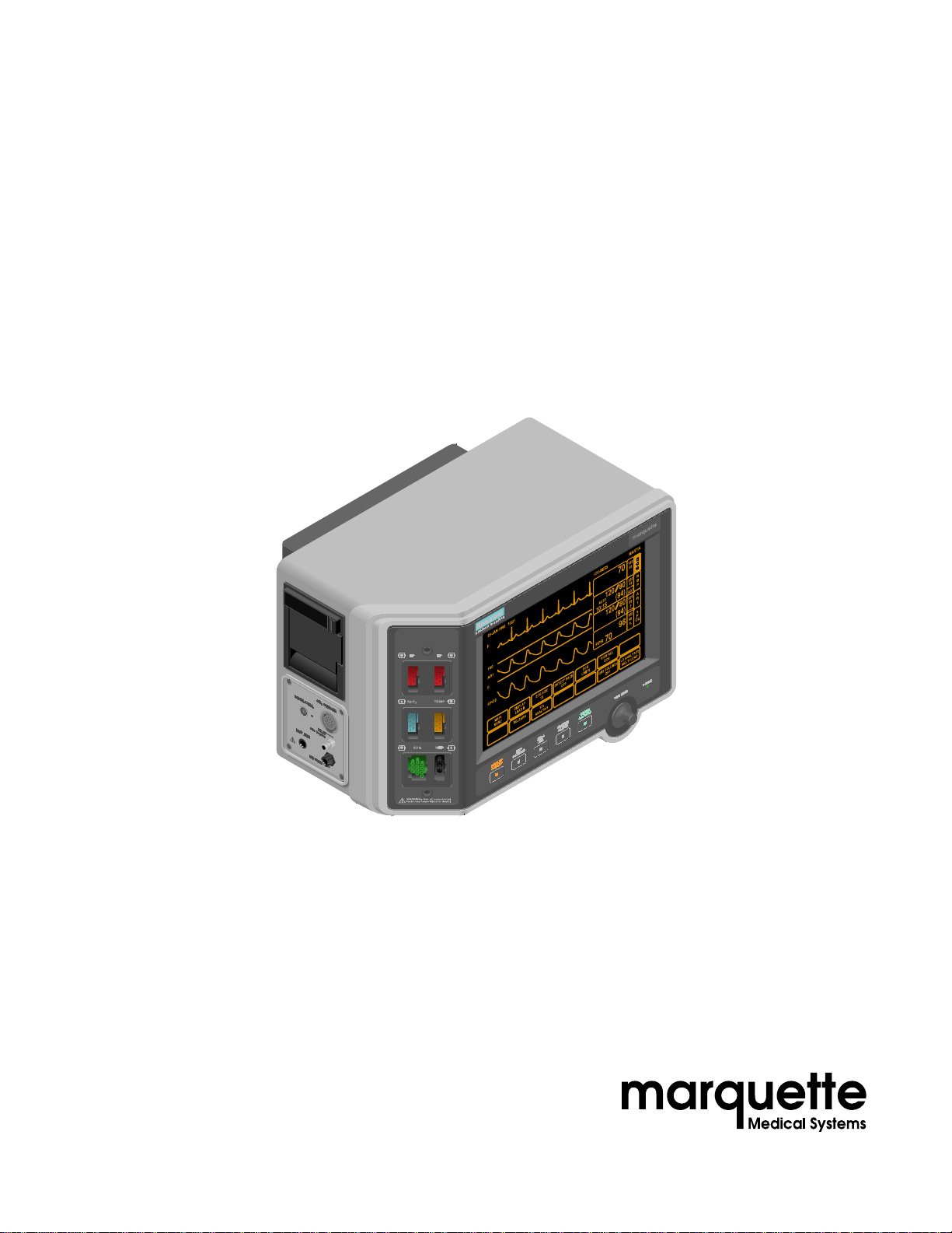
Eagle
®
3000 Patient Monitor
Data Manual
Page 2

NOTE:
Trademarks
Due to continuing product innovation, specifications in this manual are
subject to change without notice.
Trademarked names appear throughout this document. Rather than list the
names and entities that own the trademarks or insert a trademark symbol
with each mention of the trademarked name, the publisher states that it is
using the names only for editorial purposes and to the benefit of the
trademark owner with no intention of improperly using that trademark.
ACCUSKETCH, APEX, AQUA-KNOT, ARCHIVIST, BABY MAC, CASE, CD
TELEMETRY, CENTRA, CHART GUARD, CINE 35, CORO, COROMETRICS,
CRG PLUS, DIGISTORE, Digital DATAQ, E for M, EAGLE, Event-Link,
HELLIGE, IMAGE STORE, LASER SXP, MAC, MAC-LAB, MACTRODE,
MARQUETTE, MARQUETTE UNITY NETWORK, MARS, MAX, MEI, MEI in the
circle logo, MEMOPORT C, MIDAS SYSTEM, MIDASNET, MINISTORE,
MINNOWS, Monarch 8000, MULTI-LINK, MULTISCRIPTOR, MUSE, Neo-Trak,
OXYMONITOR, PRESSURE-SCRIBE, PRES-R-CUFF, QMI, QS, Quantitative
Medicine, Quantitative Sentinel, Qwik Connect Spiral, RAMS, SAM, SEER,
SOLAR, Spectra 400, Spectra-Tel, ST GUARD, TRAM, TRAM-NET, TRAMRAC, TRAMSCOPE, TRIM KNOB, UNITY NETWORK, UNITY twist logo, Vari-X,
Vari-X Cardiomatic, and VAS are trademarks of Marquette Medical Systems,
Inc. registered in the United States Patent and Trademark Office.
12SL, 15SL, AccuVision, ADVANTAGE, AUTOSEQ, BODYTRODE,
CardioMail, CardioServ, CardioSmart, CardioSpeak, CardioSys, CD
TELEMETRY
‚
-LAN, CENTRALSCOPE, Corolation, Corometrics Sensor Tip, CV
Mail, CV-Web, DASH, EDIC, HI-RES, IMAGE VAULT, INTELLIMOTION,
INTER-LEAD, LIFEWATCH, MARQUETTE MEDICAL SYSTEMS,
MARQUETTE
CardioWindow, MUSE CV, MUSEWord, O
‚
RESPONDER, MENTOR, MIDAS Com, MRT, MUSE
SENSOR, OMRS, OnlineABG,
2
Premium, RSVP, SILVERTRACE, SMART-PAC, SMARTLOOK, SOLARVIEW,
Spectra-Overview, Trimline, UNITY, and Universal are trademarks of
Marquette Medical Systems, Inc.
© 1997 Marquette Medical Systems, Inc. All rights reserved.
T-2
Eagle 3000 Patient Monitor
415397-038
Revision A
21 April 1997
Page 3

Table of Contents
Table of Contents
INTRODUCTION ................................................................1-1
1
Manual Information ................................................................1-2
Revision History ..........................................................1-2
Manual Purpose ..........................................................1-3
Chapter Content ..........................................................1-3
Introduction .....................................................1-3
Upper Level Overview .......................................1-3
Circuit Board Assembly Chapters ..................... 1-3
Related Manuals .........................................................1-4
Tech Memos ................................................................1-4
BBS Tech Memo Service ..............................................1-4
Safety Information ..................................................................1-5
Responsibility of the Manufacturer ..............................1-5
Intended Use ............................................................... 1-5
Equipment Symbols ....................................................1-6
Notes, Cautions, and Warnings ...................................1-7
Service Information .................................................................1-8
Service Requirements ..................................................1-8
Equipment Identification .............................................1-8
Warranty .....................................................................1-8
How to Reach Us… .................................................................1-9
Ordering Supply Items ................................................1-9
Ordering Service Parts .................................................1-9
Service Calls ................................................................1-9
Service Contracts .............................................1-9
Technical Support .....................................................1-10
For All Hardware ............................................1-10
Telemetry .......................................................1-10
Series 7000/7010 ..........................................1-10
48-Hour Turnaround Repair ..........................1-10
Service Address .............................................. 1-10
For Additional Information ........................................1-10
Revision A
2
Abbreviations .......................................................................1-11
UPPER LEVEL OVERVIEW ................................................. 2-1
Upper Level Part Numbers ......................................................2-2
Use Field Service Manual First ....................................2-2
Model Numbers ...........................................................2-2
Circuit Board Part Numbers ...................................................2-3
Exploded View PN 414888-001J/002J/003F/004J/005F ....... 2-4
Parts List PN 414888-001J/002J/003F/004J/005F ..............2-9
Eagle 3000 Patient Monitor
415397-038
i
Page 4

Table of Contents
Switches and Controls PN 800772-002A ............................... 2-12
PCB Connectors PN 800772-002A ........................................2-13
Parts Location Diagram PN 800772-002A ............................. 2-19
Parts List PN 800772-002A ................................................... 2-21
Schematic Diagram PN SD800772-002A ...............................2-24
POWER SUPPLY ASSEMBLY AND PCB ............................... 3-1
3
4
Introduction ...........................................................................3-2
Exploded View PN 414641-001C .............................................3-3
Parts List PN 414641-001C .....................................................3-5
Switches and Controls PN 800706-001C ................................. 3-6
PCB Connectors PN 800706-001C ..........................................3-7
Parts Location Diagram PN 800706-001C ...............................3-8
Parts List PN 800706-001C ...................................................3-10
Schematic Diagram PN SD800706-001B ............................... 3-14
OPTION ASSEMBLIES AND PCBs .......................................4-1
Introduction ...........................................................................4-2
Exploded View PN 416021-001C/002C ...................................4-3
Parts List PN 416021-001C .....................................................4-5
Parts List PN 416021-002C .....................................................4-6
Exploded View PN 418394-001A/002A ...................................4-7
Parts List PN 418394-001A ..................................................... 4-9
Parts List PN 418394-002A ................................................... 4-10
Switches and Controls PN 800836-002A ............................... 4-11
PCB Connectors PN 800836-002A ........................................4-12
Parts Location Diagram PN 800836-002A ............................. 4-17
Parts List PN 800836-002A ................................................... 4-18
Schematic Diagram PN SD800836-002A ...............................4-20
Switches and Controls PN 801318-001A ............................... 4-29
PCB Connectors PN 801318-001A ........................................4-30
ii
Eagle 3000 Patient Monitor
415397-038
Revision A
Page 5

Table of Contents
Parts Location Diagram PN 8013138-001A ..........................4-35
Parts List PN 801318-001A ................................................... 4-36
Schematic Diagram SD801318-001A ....................................4-38
Switches and Controls PN 800862-001E ...............................4-47
PCB Connectors PN 800862-001E ........................................4-48
Parts Location Diagram PN 800862-001E .............................4-50
Parts List PN 800862-001E ................................................... 4-53
Schematic Diagram SD800862-001E .................................... 4-56
DATA ACQUISITION ASSEMBLY AND PCB .........................5-1
5
Introduction ...........................................................................5-2
Exploded View PN 414887-001B .............................................5-3
Parts List PN 414887-001B .....................................................5-4
Switches and Controls PN 800776-001B ................................. 5-5
PCB Connectors PN 800776-001B .......................................... 5-6
Parts Location Diagram PN 800776-001B ...............................5-8
Parts List PN 800776-001B ...................................................5-10
Schematic Diagram PN SD800776-001B ............................... 5-14
Revision A
Eagle 3000 Patient Monitor
415397-038
iii
Page 6

For your notes
Table of Contents
iv
Eagle 3000 Patient Monitor
415397-038
Revision A
Page 7

1
INTRODUCTION
Manual Information ................................................................ 1-2
Revision History .......................................................... 1-2
Manual Purpose .......................................................... 1-3
Chapter Content .........................................................1-3
Introduction .....................................................1-3
Upper Level Overview ....................................... 1-3
Circuit Board Assembly Chapters ..................... 1-3
Related Manuals .........................................................1-4
Tech Memos ................................................................ 1-4
BBS Tech Memo Service .............................................. 1-4
Safety Information .................................................................. 1-5
Responsibility of the Manufacturer .............................. 1-5
Intended Use ............................................................... 1-5
Equipment Symbols .................................................... 1-6
Notes, Cautions, and Warnings ................................... 1-7
Service Information ................................................................1-8
Service Requirements .................................................. 1-8
Equipment Identification ............................................. 1-8
Warranty .....................................................................1-8
How to Reach Us… ................................................................. 1-9
Ordering Supply Items ................................................1-9
Ordering Service Parts ................................................. 1-9
Service Calls ...............................................................1-9
Service Contracts ............................................. 1-9
Technical Support ..................................................... 1-10
For All Hardware ............................................ 1-10
Telemetry ....................................................... 1-10
Series 7000/7010 .......................................... 1-10
48-Hour Turnaround Repair ..........................1-10
Service Address .............................................. 1-10
For Additional Information ........................................ 1-10
Abbreviations ....................................................................... 1-11
Revision A
Eagle 3000 Patient Monitor
415397-038
1-1
Page 8

Manual Information
INTRODUCTION: Manual Information
Revision History
Revision Title Manual PN Date Comment
A Eagle 3000 Patient
Monitor Data Manual
Each page of this manual has a revision letter, located at the
bottom of the page, that identifies the manual’s update level. This
may be important if you have different updates to a manual and
don’t know which is the most current.
For the initial release, the manual has the revision letter A. For the
first update of the manual, the manual receives the revision letter
B, and so on. The table below indicates the revision history of this
manual.
Table 1-1. Revision History
415397-038 21 April 1997 Initial release of this
manual.
1-2
Eagle 3000 Patient Monitor
415397-038
Revision A
Page 9

INTRODUCTION: Manual Information
Manual Purpose
Chapter Content
Introduction
Upper Level Overview
This manual is a supplement to the field service manual, Eagle
3000 Patient Monitor Field Service Manual , PN 415397-003. If you
need equipment overview, maintenance, troubleshooting,
calibration, configuration or upper level assembly information,
order the field service manual.
This manual supplies detailed technical information for service
representatives and technical personnel so they may troubleshoot
the equipment to a circuit board or component level.
Users of this manual are expected to have a strong background in
electronics, including analog and digital circuity with
microprocessor and micro-controller architecture.
This manual is organized into five chapters, summarized as
follows:
Chapter one describes the service manual and chapter contents
and provides general information on safety, service requirements,
equipment symbols, and serial number identification.
Chapter two gives the upper level model part numbers and
presents the upper assembly interconnection diagram and signal
names. Information regarding the main processor PCB,
pn 800772-002, can also be found in chapter two.
Circuit Board Assembly
Chapters
Power Supply
Eagle 3000 Options PCB
Acquisition Processor PCB
Each of the subsequent chapters describe a circuit board or
assembly that may include any or all of the following:
■
General information
■
List of switches and controls
■
List of input and output connector signals
■
Exploded view or parts location diagram
Parts list
■
Schematic diagram
■
■
Updated data describing revisions to the circuit boards and
major assemblies, if applicable
Chapter three provides all information available for the power
supply assembly, pn 414641-001, and for the power supply PCB,
pn 800706-001.
Chapter four provides all information available for the Eagle 3000
option assemblies, pn 416021-001 and -002, as well as
information for the Eagle 3000 option PCBs, pn 800836-002,
800862-001, and 801318-001.
Chapter five provides all information available for the acquisition
processor (DAS) assembly, pn 414887-001, and for the acquisition
processor PCB, pn 800776-001.
Revision A
Eagle 3000 Patient Monitor
415397-038
1-3
Page 10
INTRODUCTION: Manual Information
Related Manuals
Part Number Name
415397-003 Eagle 3000 Patient Monitor Field Service Manual
405040-088 Centralscope 12 Central Station Service Manual
405040-018 Centralscope 12C Central Station Service Manual
405040-164 Centralscope Central Station Field Service Manual
Part Number Name
415397-042 Eagle 3000 Monitor Operator’s Manual (for software version 3)
415397-043 Eagle 3000 Monitor Instructions (for software version 3)
Check these documents if you need additional information on the
Marquette Monitoring system.
Table 1-2. Service Documents
Table 1-3. Operator Documents
Tech Memos
BBS Tech Memo Service
Marquette Service issues technical memos that aid service
personnel in servicing and maintaining the equipment. Tech
Memos supply important information about changes to the
equipment, typical problems, and how to solve those problems.
Tech Memos are also written to describe hardware and software
upgrades.
Tech Memos are automatically distributed to all Marquette Field
Service personnel, and are available to customers by subscription.
Contact Technical Support for more information or to subscribe.
For the address or telephone number, see the “How to Reach Us...”
pages presented later in this manual.
Designed primarily for biomedical technicians, the BBS Tech
Memo Service provides “instant” on-line access to the latest
Marquette maintenance and repair information. Subscribers with
an IBM or IBM-compatible computer and modem can link-up to
the MEITIS system and download technical publications as well as
send and receive messages from technical support
representatives. Call Service Contracts at 800-552-3248 for
subscription information.
1-4
Eagle 3000 Patient Monitor
415397-038
Revision A
Page 11

Safety Information
INTRODUCTION: Safety Information
Responsibility of the
Manufacturer
Intended Use
Marquette Medical Systems is responsible for the effects of safety,
reliability, and performance only if:
Assembly operations, extensions, readjustments,
■
modifications, or repairs are carried out by persons authorized
by Marquette.
The electrical installation of the relevant room complies with
■
the requirements of the appropriate regulations.
The equipment is used in accordance with the instructions for
■
use.
This device is intended for use under the direct supervision of a
licensed health care practitioner.
To ensure patient safety, use only parts and accessories
manufactured or recommended by Marquette Medical Systems.
Contact Marquette Medical Systems for information before
connecting any devices to this equipment that are not
recommended in this manual.
Revision A
Eagle 3000 Patient Monitor
415397-038
1-5
Page 12
CAUTION
INTRODUCTION: Safety Information
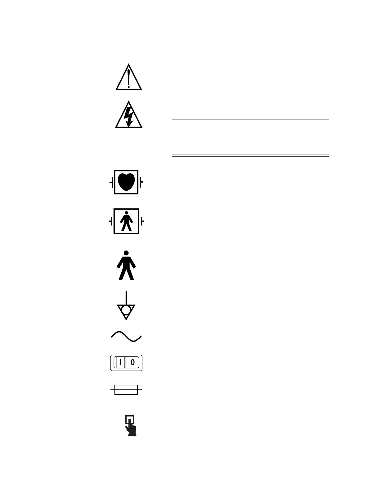
Equipment Symbols
The following symbols appear on the equipment.
NOTE: Some symbols may not appear on all equipment.
ATTENTION: Consult accompanying documents before using
the equipment.
In Europe, this symbol means dangerous or high voltage. In the
United States, this symbol represents the caution notice below:
To reduce the risk of electric shock, do NOT
remove cover (or back). Refer servicing to
qualified personnel.
Defibrillator-proof type CF equipment; type CF equipment is
specifically designed for applications where a conductive
connection directly to the heart is established. The paddles
indicate the equipment is defibrillator proof.
Defibrillator-proof type BF equipment; type BF equipment is
suitable for intentional external and internal application to the
patient, excluding direct cardiac application. Type BF
equipment is type B equipment with an F-type isolated (floating)
part. The paddles indicate the equipment is defibrillator proof.
PRESS
Type B equipment; type B equipment is suitable for intentional
external and internal application to the patient, excluding direct
cardiac application.
Equipotentiality
Alternating current (AC)
Power;
Fuse
Indicates where to press to open the door on the Series 7160
Direct Digital Writer.
II
II
= ON;
OOOO
= OFF
1-6
Eagle 3000 Patient Monitor
415397-038
Revision A
Page 13

NOTE
CAUTION
WARNING
INTRODUCTION: Safety Information
Notes, Cautions, and
Warnings
Notes, cautions, and warnings are used in this manual to provide
additional information to service personnel.
A note conveys special instructions to service
personnel to highlight an operating procedure,
practice, etc. Notes may precede or follow the
applicable text, depending on the material to be
highlighted.
The purpose of a caution is to inform service
personnel of an operating procedure, practice, etc.,
which if not strictly observed, could result in
possible damage to the equipment. Cautions
always precede the applicable text.
A warning provides instructions to service
personnel that if an operating procedure, practice,
etc., is not followed, personal injury may result.
Warnings always precede the applicable text.
Revision A
Eagle 3000 Patient Monitor
415397-038
1-7
Page 14

Service Information
INTRODUCTION: Service Information
Service Requirements
Equipment
Identification
Follow the service requirements listed below.
Refer equipment servicing to Marquette’s authorized service
■
personnel only.
Any unauthorized attempt to repair equipment under
■
warranty voids that warranty.
It is the user’s responsibility to report the need for service to
■
Marquette Medical Systems or to one of their authorized
agents.
Failure on the part of the responsible individual, hospital, or
■
institution using this equipment to implement a satisfactory
maintenance schedule may cause undue equipment failure
and possible health hazards.
Regular maintenance, irrespective of usage, is essential to
■
ensure that the equipment will always be functional when
required.
Every Marquette Medical Systems device has a unique serial
number for identification. The serial number appears on the
product label on the base of each unit under the Trim knob
control.
Month
Manufactured
A = January
B = February
C = March
D = April
E = May
F = June
G = July
H = August
J = September
K = October
L = November
M = December
Warranty
D 1 XX 0005 G XX
Year
Manufactured
1 = 1991
2 = 1992
3 = 1993
(and so on)
Product Code
Two-character
product
descriptor
1 year.
Product
Sequence
Number
Manufacturing
number (of
total units
manufactured.)
Division
F = Cardiology
G = Monitoring
Device Characteristics
One or 2 letters that
further describe the unit,
for example:
P = prototype not
conforming to marketing
specification
R = refurbished equipment
S = special product
documented under
Specials part numbers
U = upgraded unit
1-8
Eagle 3000 Patient Monitor
415397-038
Revision A
Page 15

How to Reach Us…
INTRODUCTION: How to Reach Us…
The following are telephone numbers and addresses for contacting
various Marquette Medical Systems Service and Supplies Division
personnel.
Ordering Supply Items
Ordering Service Parts
Supply items are generally items used during normal operation of
a product. Leadwires, electrode paste, patient cables, and printer
paper are examples of supply items.
Make telephone inquiries about supply items at:
1-800-558-5102 (U.S. only)
1-561-575-5000 (outside the U.S.)
Address orders or inquiries to:
Marquette Medical Systems Service and Supplies
P.O. Box 9100
100 Marquette Drive
Jupiter, FL 33468-9100
Attn: Supplies
Service parts are items that are not expended in the normal
operation of the product. They are generally replacements for
defective or malfunctioning items inside the product. Service
parts include PCB assemblies, electronic components, internal
cables and harnesses, software or firmware, and operator and
service manuals. When ordering additional operator manuals,
remember to notate the software version from the start-up screen.
Service Calls
Service Contracts
A part number for the item to be replaced is necessary for ordering
a service part. If the part number for the desired item is
unobtainable, the following will be necessary to order the item:
■
model and serial number of the equipment,
part number/name of the assembly where the item is used,
■
item name, and
■
where applicable, reference designation (eg, R13, S12, U32).
■
To open a service call with Marquette Medical Systems Service,
contact a Service Dispatcher at:
1-800-558-7044 (U.S. only)
1-561-575-5000 (outside the U.S.)
For any questions about Service Contracts, contact the service
contract operator at:
1-800-552-3248
Revision A
Eagle 3000 Patient Monitor
415397-038
1-9
Page 16

INTRODUCTION: How to Reach Us…
Technical Support
For All Hardware
Telemetry
Series 7000/7010
48-Hour Turnaround Repair
Technical Support has the most current information about your
equipment and can provide assistance with any technical
questions or problems.
For technical advice concerning any equipment in your Marquette
Medical Systems monitoring system, contact Tech Support—
Monitoring Hardware at:
1-800-558-7822
For technical advice concerning your Telemetry system, contact
Tech Support—Telemetry at:
1-800-552-3243
For technical advice concerning Series 7000/7010 patient
monitoring equipment, contact Tech Support:
1-800-443-0980
Some Marquette products (Input Modules, Tram modules, Series
7700 ECG Telemetry Transmitters, and CD Telemetry
Transmitters) are repaired on a 48-hour turnaround basis.
To inquire about status of 48-hour turnaround repair items, or if
you have questions before shipping an assembly to be repaired,
call:
Service Address
For Additional
Information
1-800-552-3243
Send items for 48-hour repair and all monitoring repair items to:
Marquette Medical Systems Service and Supplies
P.O. Box 9100
100 Marquette Drive
Jupiter, FL 33468-9100
Attn: Monitoring Repair
The main switchboard operator will direct your call to the person
most able to assist you. For any other questions or problems,
contact the main switchboard operator at:
1-800-558-5120
1-10
Eagle 3000 Patient Monitor
415397-038
Revision A
Page 17

Abbreviations
INTRODUCTION: Abbreviations
A
A ampere
Ampl amplifier
Ave Avenue
B
BDGH binding head
Btu/hr British thermal
units per hour
C
CA California
Cap capacitor
CMOS complimentary
metal-oxide
semiconductor
Comp composition
D
DC, dc direct current
E
eg for example
EPROM electronically
programmable
read only memory
ESD electrostatic
discharge
etc et cetera, and so
forth
F
FL Florida
G
g gram
I
in inch
Inc incorporated
L
lb pound
LED light-emitting
diode
M
mA milliampere
MHz megahertz
mm millimeter
mmHg millimeter of
mercury
MOSFET metal-oxide
semiconductor
field-effect
transistor
MPE metallized
polycarbonate
epitaxial
MPP metallized
polypropylene
N
No number
O
oz ounce
P
PA pulmonary artery
PC printed circuit,
personal
computer
PCB printed circuit
board
pF picofarad
PLCC plastic leaded chip
carrier
PNH pan head
Q
Qty quantity
R
RAM random access
memory
Res resistor
ROM read-only memory
S
SM surface mount
SST stainless steel
SvO
2
Tant tantalum
TTL transistor-
V volt, voltage
W watt, West
w/ with
WI Wisconsin
WW wire wound
➔ continued
< less than
≤ less than or equal
µF microfarad
µH microhenry
Ω ohm
% percent
mixed venous
oxygen saturation
T
transistor logic
V
W
Other
to
K
K kilo, kilohm
Revision A
Eagle 3000 Patient Monitor
415397-038
1-11
Page 18

For your notes
INTRODUCTION: Abbreviations
1-12 Revision A
Eagle 3000 Patient Monitor
415397-038
Page 19

2
UPPER LEVEL OVERVIEW
Upper Level Part Numbers ...................................................... 2-2
Use Field Service Manual First .................................... 2-2
Model Numbers ........................................................... 2-2
Circuit Board Part Numbers ................................................... 2-3
Exploded View PN 414888-001J/002J/003F/004J/005F ....... 2-4
Parts List PN 414888-001J/002J/003F/004J/005F ..............2-9
Switches and Controls PN 800772-002A ............................... 2-12
PCB Connectors PN 800772-002A ........................................ 2-13
Parts Location Diagram PN 800772-002A ............................. 2-19
Parts List PN 800772-002A ................................................... 2-21
Schematic Diagram PN SD800772-002A ............................... 2-24
Revision A
Eagle 3000 Patient Monitor
415397-038
2-1
Page 20

UPPER LEVEL OVERVIEW: Upper Level Part Numbers
Upper Level Part Numbers
Use Field Service
Manual First
Model Numbers
It is recommended that you first familiarize yourself with the
information presented in the Troubleshooting section of the Eagle
3000 Patient Monitor Field Service Manual , pn 415397-003. The
troubleshooting information will help you narrow service problems
down to one of the replaceable assemblies.
After you have determined which assembly requires replacement,
use the input/output connector list, parts location diagram, parts
list, and/or schematic diagram presented in this manual to repair
the assembly.
Also refer to the Eagle 3000 Patient Monitor Field Service Manual ,
pn 415397-003, for preventative maintenance, calibration, and
configuration procedures.
The following model part numbers are discussed in this manual
for the Eagle 3000 patient monitor.
Table 2-1. Model Part Numbers
Model Part Number
Eagle 3000 Patient Monitor 414888-001
414888-002
414888-003
414888-004
414888-005
2-2
Eagle 3000 Patient Monitor
415397-038
Revision A
Page 21
NOTE
UPPER LEVEL OVERVIEW: Circuit Board Part Numbers
Circuit Board Part Numbers
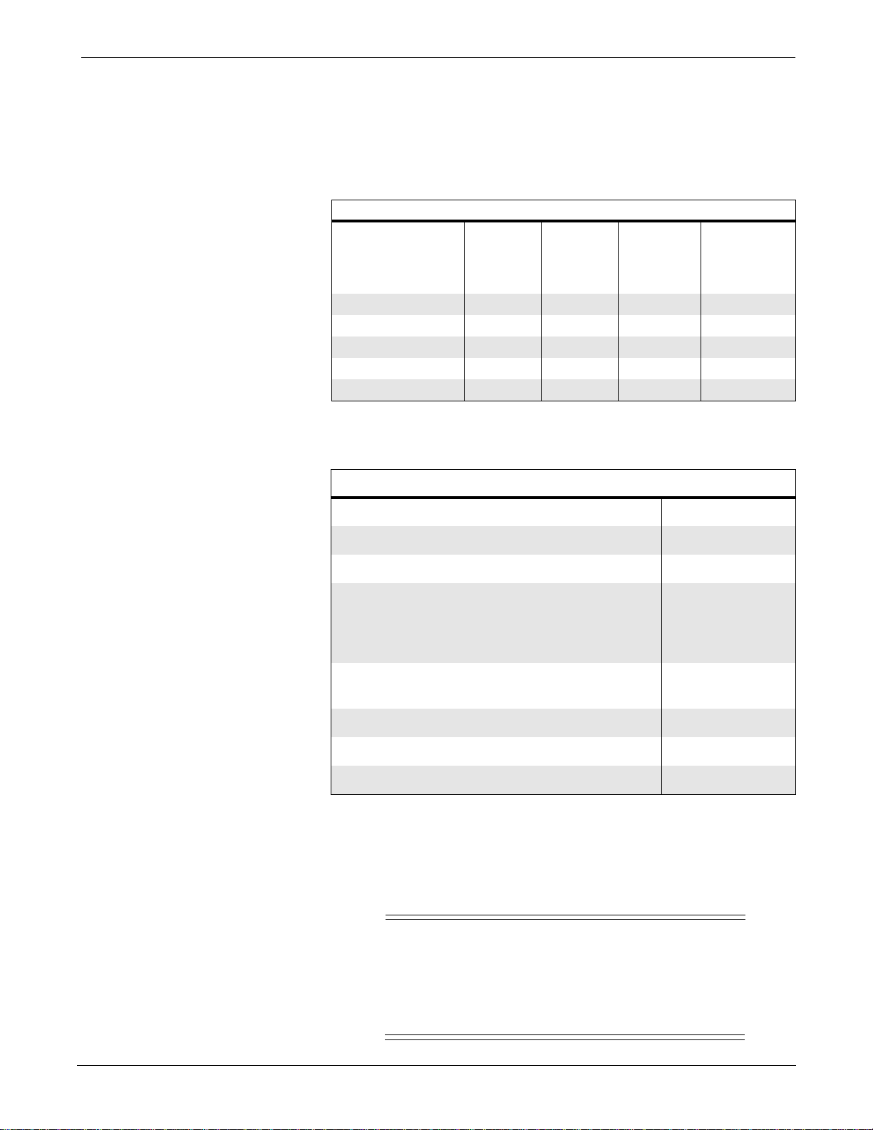
The various model parameters of the Eagle 3000 patient monitor
are listed in the table below. Refer to your Eagle 3000 model
number for the correct replacement part numbers.
Model PN NBP Writer ETCO2
414888-001 X – – –
414888-002 X – – X
414888-003 X – X X
414888-004 X X – X
414888-005 X X X X
In addition to the main processor PCB, pn 800772-002, the table
below lists the other assemblies and circuit boards described in
this manual.
Table 2-2. List of Options
Defib
Sync/
Remote
Alarm
Table 2-3. Assemblies and Circuit Boards
Item Part Number
Power Supply Assembly 414641-001
Power Supply PCB 800706-001
Option Assemblies 416021-001
416021-002
418394-001
418394-002
Defib Sync/Remote Alarm PCB
1
800836-002
801813-001
ETCO2 PCB 800862-001
Data Acquisition Assembly 414887-001
Data Acquisition PCB 800776-001
1
There are two PCBs for the defib sync/remote alarm assembly. PN
800836-002 is used on older Eagle 3000 monitors that have the
1/4-inch phone jack type connector for remote alarm. PN 801813-001 is
used for new Eagle 3000 monitors, which have a 9-pin subminiature “D”
connector for remote alarm. Refer to chapter 4 for more information
about the option assemblies.
Revision A
The exploded view and parts lists for the upper level
assembly, pn 414888-001J through -005F, on the
following pages show the new, 9-pin “D” connector.
For information about the old, 1/4-inch phone jack
type connector, please refer to chapter 4.
Eagle 3000 Patient Monitor
415397-038
2-3
Page 22
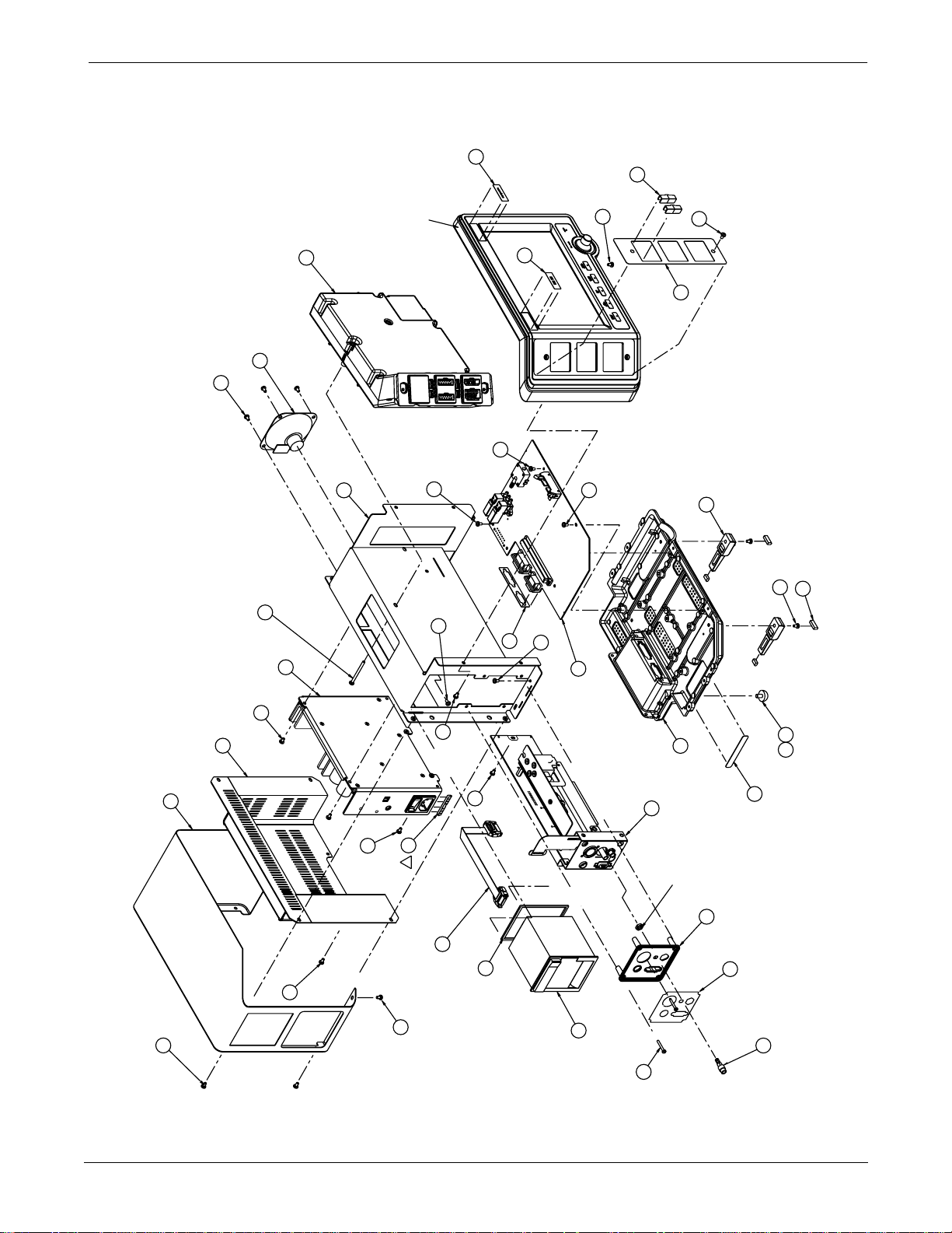
UPPER LEVEL OVERVIEW: Exploded View PN 414888-001J/002J/003F/004J/005F
Exploded View PN 414888-001J/002J/003F/004J/005F
Page 1 of 5
50
58
42
46
A1
2 PLACES
42
INSERT THIS
SCREW SECOND
NOTE:
A2
47
REFER TO ASSEMBLY
DETAIL A, SHEET 3
A4
21
A5
25
4 PLACES
36
4 PLACES
NOTE:
13
2 PLACES
38
INSERT THESE TWO SCREWS,
BUT DO NOT TIGHTEN UNTIL
THE BEZEL AND DAS ASSEMBLIES
HAVE BEEN SECURED.
NOTE:
8
9
16
A3
2 PLACES
36
42
2 PLACES
36
APPLICABLE ONLY
IF ITEM 14 IS NOT
PRESENT
36
4 PLACES
42
42
INSERT THIS
SCREW FIRST
32
51
4 PLACES
36
2 PLACES
39
52
INSTALL PARTS SHOWN,
SCRAP REMAINING PARTS
IN PACKAGE.
NOTE:
19
11
2 PLACES
2 PLACES
41
45
2 PLACES
23
HAND TIGHTEN
26
5
2-4
4 PLACES
36
2 PLACES
36
61
37
E
2 PLACES
W2
4
35
2 PLACES
36
CABLE MUST BE THREADED
THRU THE SLOT, IN THE
WRITER MOUNTING AREA
OF THE FRAME.
NOTE:
Eagle 3000 Patient Monitor
415397-038
W3
OF INLET PORT FITTING.
REMOVE WASHER AND DO NOT USE.
NOTE:
TORQUE NUT TO 10 in-LBS
APPLY ITEM 62 TO THREADS
OF ITEM 34.
NUT AND WASHER ARE PART
10
56
15
A8
40
4 PLACES
SEE NOTE 2
MOUNT LABEL ON VERTICAL
SURFACE, JUST BELOW THE
FLANGE.
NOTE:
34
Revision A
Page 23
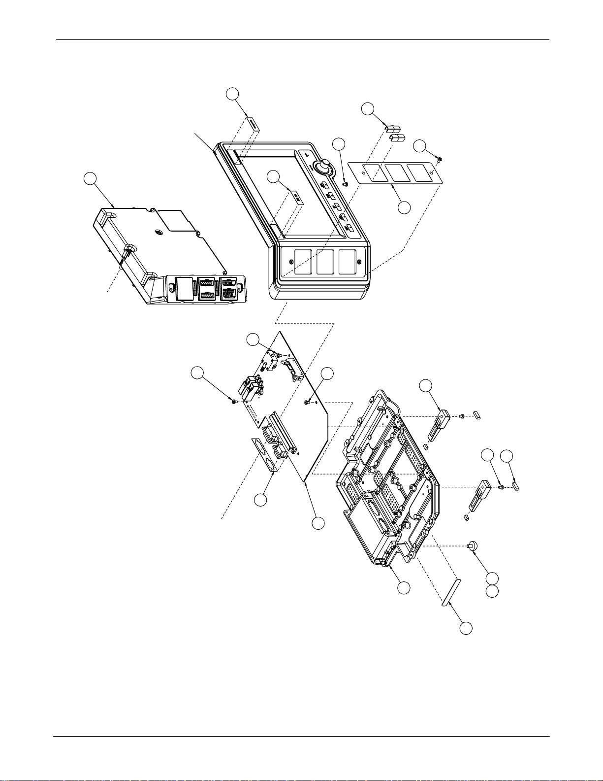
Page 2 of 5
A4
21
UPPER LEVEL OVERVIEW: Exploded View PN 414888-001J/002J/003F/004J/005F
50
58
REFER TO ASSEMBLY
DETAIL A
51
2 PLACES
42
2 PLACES
39
52
4 PLACES
42
42
SCREW FIRST
INSERT THIS
NOTE:
42
SCREW SECOND
INSERT THIS
NOTE:
32
46
A1
SCRAP REMAINING PARTS
IN PACKAGE.
INSTALL PARTS SHOWN,
NOTE:
19
11
REFER TO
ASSEMBLY
DETAIL B
5
2 PLACES
2 PLACES
41
45
2 PLACES
HAND TIGHTEN
26 23
Revision A
Eagle 3000 Patient Monitor
415397-038
SEE NOTE 2
SURFACE, JUST BELOW THE
MOUNT LABEL ON VERTICAL
FLANGE.
NOTE:
2-5
Page 24
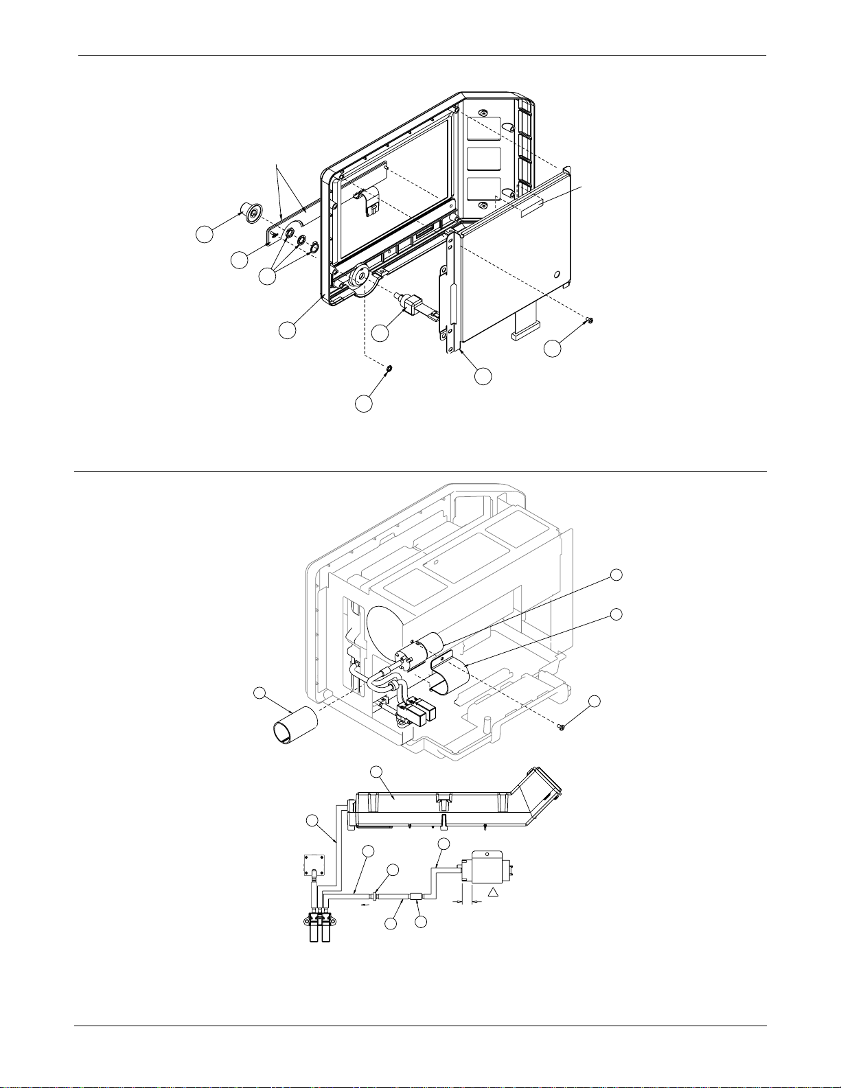
age 3 of 5
UPPER LEVEL OVERVIEW: Exploded View PN 414888-001J/002J/003F/004J/005F
NOTE:
REMOVE ADHESIVE
BACKING 2 PLACES
PLACE UID LABEL
AS SHOWN
15
A9
57
17
NOTE:
HARDWARE ITEMS INCLUDED
WITH SWITCH ASSEMBLY.
TORQUE 10 in/lbs.
REF.
12
17
A10
43
TORQUE 1.5 in/lbs
3 PLACES
A7
18
W1
36
4 PLACES
REMOVE BACKING AND
WRAP PUMP PRIOR TO
MOUNTING CLAMP.
24
6.00 ±10
ASSEMBLY DETAIL A
11
3
1.75 ±.10
3
FLOW
1.00 ±.10
REF.
6
3
28
22
36
2.25 ±.10
3
E
.700 ±.10
7
2-6
ASSEMBLY DETAIL B
Eagle 3000 Patient Monitor
415397-038
Revision A
Page 25
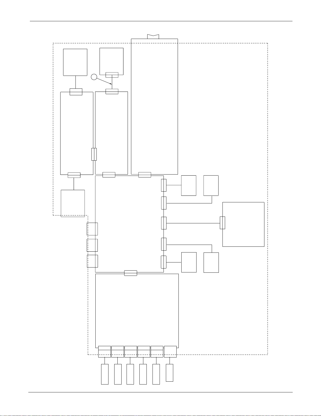
Page 4 of 5
UPPER LEVEL OVERVIEW: Exploded View PN 414888-001J/002J/003F/004J/005F
A12
PUMP
1
P12A
4
J11A
A11
ETCO2 SUBSYSTEM
A
3
J
11
W
1P3
FLEX
W3
REF.
4
A2J14
A11J14
AA6J
2
WRITER
A8
1
J8A
2
P2W
W2
1
P2W
3
J2A
A2
OPTION PCB
6J1
J3A
A
A3
POWER SUPPLY
3
2J1
A5P1
A1J5 A1J4
A6P1
A5
SPEAKER
A6
NBP PUMP
A1J9
A1J10
A1J12
SWITCHA9PANEL
W1
TRIM
KNOB
A10
W1P1
A7J3
A7
DISPLAY
A1
CPU
AA
8J1
8J4
A4
DAS
17J4
A
4
16
J
A15W4A
A1J3
W1P2
A1J25
A10P1
A1J7
A9P1
19AJ4A
18J4
Revision A
ELECTRODES
ECG/RESP
SENSORS
TEMP
PULSE OX
PROBE
TRANSDUCER
PRESSURE
Eagle 3000 Patient Monitor
415397-038
PRESSURE
TRANSDUCER
NBP CUFF
2-7
Page 26
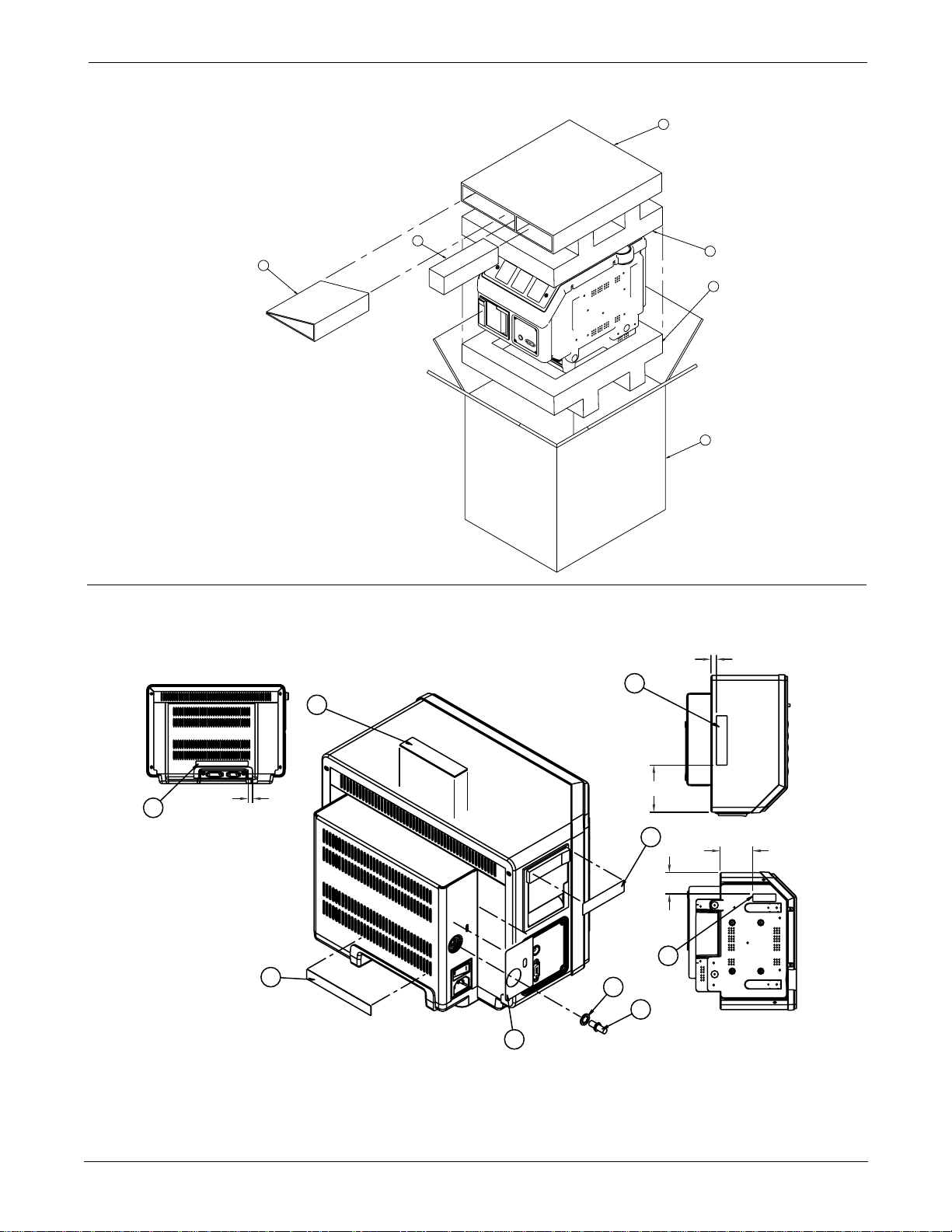
UPPER LEVEL OVERVIEW: Exploded View PN 414888-001J/002J/003F/004J/005F
Page 5 of 5
49
31
NOTES:
1) LOOSE ITEMS MAY BE SHIPPED WITH THE UNIT IF
SPACE PERMITS OR PACKAGED SEPERATELY.
2) MARK LABEL WITH THE FOLLOWING; "MODEL NAME",
SERIAL NUMBER AND APPROPRIATE BARCODE.
33
30
58
29
BACK VIEW
55
54
REF.
NOTE:
LABELS TO BE PLACED APPROX. AS SHOWN.
DIMENSIONS ARE FOR REFERENCE ONLY.
.38 REF.
54
53
NOTE:
CENTER LABEL AROUND
DIMPLE
55
REF.
5.0 REF.
48
2.5 REF
60
2
1
TORQUE 17 in-LBS
.25 REF.
TOP VIEW
2.7 REF
BOTTOM VIEW
2-8
Eagle 3000 Patient Monitor
415397-038
Revision A
Page 27
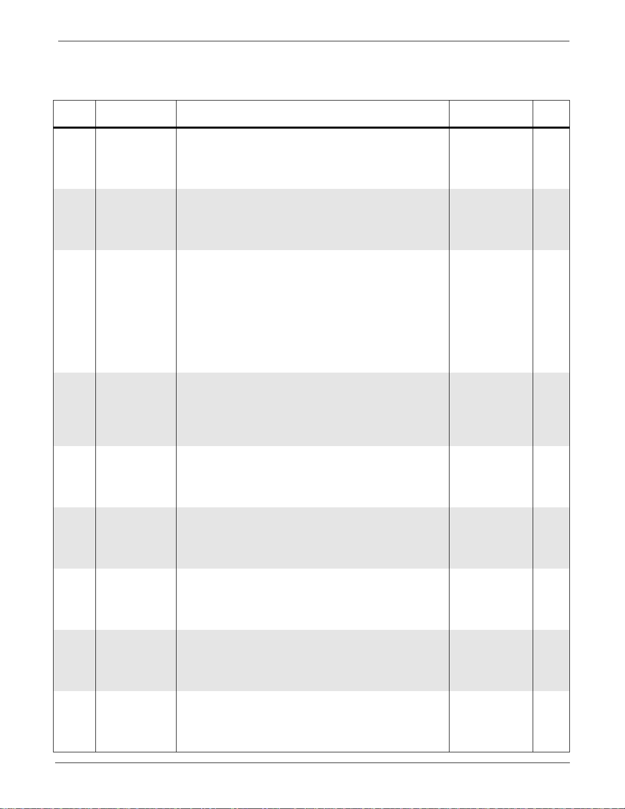
UPPER LEVEL
VERVIEW
UPPER LEVEL OVERVIEW: Parts List PN 414888-001J/002J/003F/004J/005F
Parts List PN 414888-001J/002J/003F/004J/005F
Item
1 Plug, MC, Equipotential 400040-001 1
2 Washer, Lock, Serrated, Male/Female, No 6 400041-001 1
3 Tubing, Silastic 401582-001 AR
4 W2 Harness Assembly, Writer Data 402642-007 1
5 Label, Model/Serial Number 404525-006 1
6 Check Valve, 0.125 inch 418437-001 1
7 Filter, 43 Micron 404679-001 1
8 Rear Cover 412847-001 1
9 Top Cover (For 414888-001 Only)
10 Side Connector Cover (For 414888-002 and -004
11 Base, Diecast 412857-002 1
12 Bezel, Monitor 412858-001 1
13 Chassis Frame 412868-003 1
14 A8 Thermal Writer Assembly, 2-inch, STAR (For
15 Knob, Trim Knob, Soft 414622-001 1
16 A3 Power Supply Assembly, 5/12 Volt 414641-001 1
17 A10 Switch Assembly, Rotary 414642-001 1
18 A7 Display Processor PCB Assembly 414704-002 1
19 Foot, Two-Position 414793-001 1
20 Not used in this assembly
21 A4 Data Acquisition PCB Assembly 414887-001 1
22 Clamp, NBP Pump 414992-002 1
23 Foot, Rubber, 0.62 diameter 415054-002 2
24 Foam Pump Mount 415081-001 1
25 A5 Speaker Assembly 415091-001 1
26 Cement, Loctite 4851-003 AR
27 Not used in this assembly
28 A6 NBP Pump Assembly 415321-001 1
29 Carton, Shipping, Eagle 3000 415337-001 1
30 Insert, Foam, Glued, Top Section 415338-001 1
31 Eagle 3000 Field Service Manual 415397-003 AR
32 Gasket, EMI Shield 415478-002 1
33 Insert Spacer, Packaging 415582-001 1
34 Connector, Luer, Female, 1/8 Barb 416229-001 1
35 Gasket, Writer 415650-001 1
36 Screw, PNH, Phillips, 6-32 x 1/4 45000-604 29
Reference
Designation
Parts List Part Number Qty
Top Cover (For 414888-002 and -003 Only)
Top Cover (For 414888-004 and -005 Only)
Only)
Side Connector Cover, ETCO2 (For 414888-003 and
-005 Only)
414888-004 and -005 Only)
412848-003
412848-002
412848-001
412849-002
412849-003
413568-001 1
1
1
1
1
1
Revision A
Eagle 3000 Patient Monitor
415397-038
2-9
Page 28
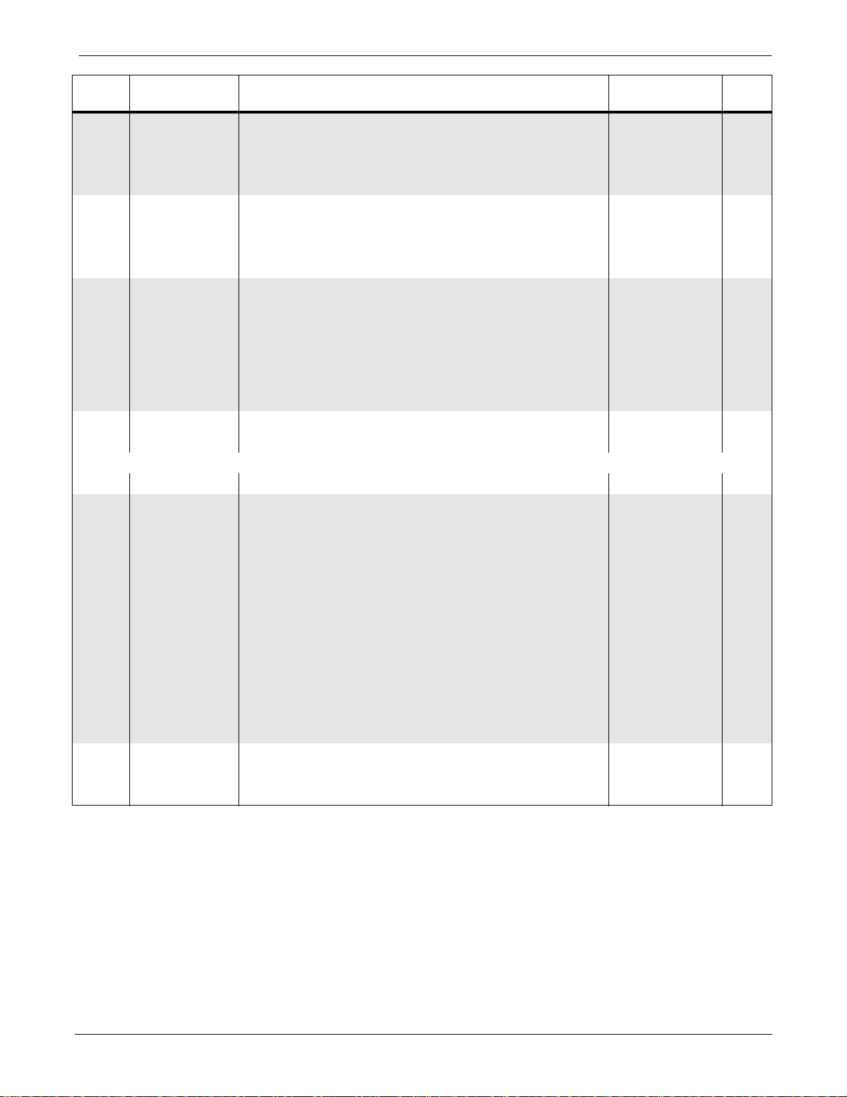
UPPER LEVEL OVERVIEW: Parts List PN 414888-001J/002J/003F/004J/005F
Item
Reference
Designation
Parts List Part Number Qty
37 Screw, PNH, Phillips, 6-32 x 3/8 45000-606 2
38 Screw, PNH, Phillips, 6-32 x 1-1/2 45000-817 2
39 Screw, PNH, Phillips, SST, 4-40 x 3/8 4502-412 2
40 Screw, PNH, Phillips, SST, 4-40 x 15/16 4502-430 4
41 Screw, BDGH, Phillips, 6-32 x 3/16 45074-606 2
42 Screw, BDGH, Phillips, 6-32 x 1/4 45074-608 8
43 Nut, Hex, 4-40 4521-104 3
45 Tape, Double-Sided (White) 4813-100 AR
46 A1 Main Processor PCB Assembly 800772-002 1
47 A2
Assembly, Eagle 3000 Options (For 414888-002 and
416021-002
1
-004 Only)
A2
Assembly, Eagle 3000 Options (For 414888-003 and
416021-001
1
-005 Only)
59 Insert, Foam, Glued, Bottom Section 415338-002 1
61 Clip, EMI 416053-002 1
62 Adhesive, Permabond 910FS 4851-074 AR
63 Adhesive, Loctite 4851-070 AR
The following items are determined by customer destination. They are included here for reference.
48 Label, Writer (Press to Open) 415570-001 1
49 Writer Paper, 3-Roll Sample 9402
1
SAMPLE-046
50 Label, Marquette
Label, Corometrics, A Marquette Company
Label, Marquette Hellige
51 Label, Eagle 3000 Patient Monitor
Label, Eagle 3000N Neonatal Monitor
52 Label, Parameter Connectors (English)
Label, Parameter Connectors (German)
Label, Parameter Connectors (French)
Label, Parameter Connectors (Swedish)
Label, Parameter Connectors (Spanish)
Label, Parameter Connectors (Italian)
Label, Parameter Connectors (English International)
413384-001
413383-002
413383-003
413383-001
413383-002
413382-001
413382-002
413382-003
413382-004
413382-005
413382-006
413382-007
-
-
-
-
-
-
-
-
-
-
-
53 Label, Voltage, Equipotential, Ratings (UL/CUL/CE) 415969-001 1
54 Label, Ethernet and ASYNC COMM Connectors 415151-001 1
55 Label, Prescription Device (USA Only) 415043-002 1
2-10
Eagle 3000 Patient Monitor
415397-038
Revision A
Page 29

UPPER LEVEL OVERVIEW: Parts List PN 414888-001J/002J/003F/004J/005F
Item
56 Label, Defib Sync, CO2, Inlet, Rmt Alm, and
Reference
Designation
Parts List Part Number Qty
415868-001
Exhaust Connectors (English)
Label, Defib Sync, CO2, Inlet, Rmt Alm, and
415858-002
Exhaust Connectors (German)
Label, Defib Sync, CO2, Inlet, Rmt Alm, and
415868-003
Exhaust Connectors (French)
Label, Defib Sync, CO2, Inlet, Rmt Alm, and
415868-004
Exhaust Connectors (Swedish)
Label, Defib Sync, CO2, Inlet, Rmt Alm, and
415868-005
Exhaust Connectors (Spanish)
Label, Defib Sync, CO2, Inlet, Rmt Alm, and
415868-006
Exhaust Connectors (Italian)
Label, Defib Sync, CO2, Inlet, Rmt Alm, and
415868-007
Exhaust Connectors (Dutch)
57 Label, Membrane Switch Panel (English)
Label, Membrane Switch Panel (German)
Label, Membrane Switch Panel (French)
Label, Membrane Switch Panel (Swedish)
Label, Membrane Switch Panel (Spanish)
Label, Membrane Switch Panel (Italian)
Label, Membrane Switch Panel (Dutch)
58 Cover, Patient Connectors (for units w/o invasive
415001-001
415001-002
415001-003
415001-004
415001-005
415001-006
415001-007
408557-002 2
blood pressure)
60 Label, UL 2601 Classification 416338-001 1
-
-
-
-
-
-
-
-
-
-
-
-
-
-
Revision A
Eagle 3000 Patient Monitor
415397-038
2-11
Page 30
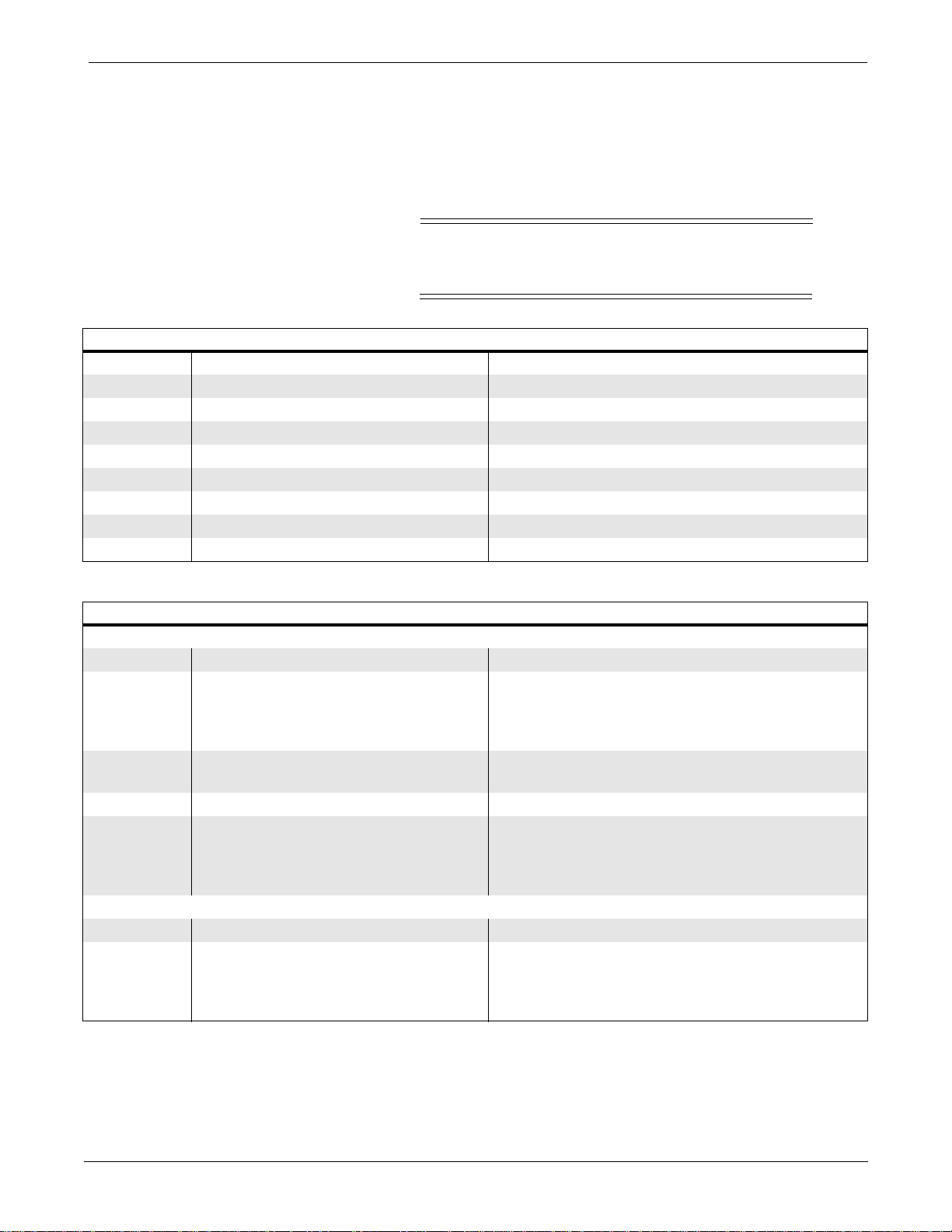
WARNING
UPPER LEVEL OVERVIEW: Switches and Controls PN 800772-002A
Switches and Controls PN 800772-002A
Listed below are all switches, controls, and LEDs found on the
circuit board.
Due to possible high voltage, always use an
insulated screwdriver while making adjustments.
Table 2-1. Controls
Designator Name Function
DS1 Green light-emiting diode Ethernet status LED
DS2 Yellow light-emiting diode Ethernet status LED
DS3 Red light-emiting diode Ethernet status LED
DS4 Green light-emiting diode General purpose diagnostic LED
DS5 Yellow light-emiting diode General purpose diagnostic LED
DS6 Red light-emiting diode General purpose diagnostic LED
DS7 Red light-emiting diode NBP diagnostic LED
DS8 Green light-emiting diode NBP diagnostic LED
Table 2-2. Switches
S1 — 4-Position DIP Switch
Designator Name Function
SW1 Software updates OPEN — Software updates enabled; NBP
calibration enabled
CLOSED — Software updates disabled; NBP
calibration disabled
SW2 Watchdog timer OPEN — Enabled
CLOSED — Disabled
SW3 Reserved for future use
SW4 Reserved for future use Current Usage:
OPEN — Normal operation
CLOSED — Forces boot code menus to be
displayed after reset
S2 — Dual Pressure Sensor Switch
Designator Name Function
S2 Dual pressure sensor switch Detects NBP over pressure condition. One
switch trips when cuff pressure is 150 mmHg
(neonatal mode); the other switch trips when
cuff pressure is 300 mmHg (adult mode).
2-12
Eagle 3000 Patient Monitor
415397-038
Revision A
Page 31
UPPER LEVEL OVERVIEW: PCB Connectors PN 800772-002A
PCB Connectors PN 800772-002A
Pin-by-pin descriptions and the signal names for each internal
PCB connector are described below.
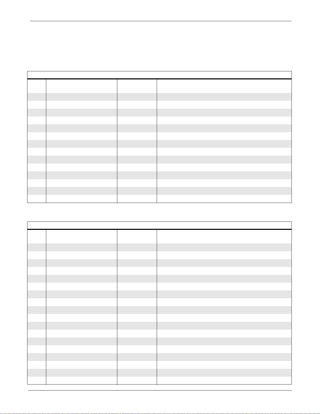
Table 2-3. Connector J2 (14-Pin Input Power Connector)
Pin Name
1 NC
2 +12 I +12 V power to processor board
3 +12 I +12 V power to processor board
4 GND O Common power return
5 GND O Common power return
6 GND O Common power return
7 +5 O +5 V power to processor board
8NC
9 +12 I +12 V power to processor board
10 +12 I +12 V power to processor board
11 GND O Common power return
12 GND O Common power return
13 GND O Common power return
14 +5 I +5 V power to processor board
Input/
Output
Description
Table 2-4. Connector J3 (26-Pin EL Display Power Connector)
Pin Name
1 +12 O +12 V power to display
2 +12 O +12 V power to display
3 +5 O +5 V power to display
4 +5 O +5 V power to display
5 Blank
6 GND I +5 V power return
7 VidU1 O Video data bit, upper half of display
8 8-bit O 8-bit
9 S O Vertical sync
10 GND I +5 V power return
11 CP1 O Horizontal sync
12 GND I +5 V power return
13 CP2 O Video clock to display
14 GND I +5 V power return
15 VidU0 O Video data bit, upper half of display
16 GND I +5 V power return
17 VidU2 O Video data bit, upper half of display
18 VidU3 O Video data bit, upper half of display
Input/
Output
Description
Revision A
Eagle 3000 Patient Monitor
415397-038
2-13
Page 32
UPPER LEVEL OVERVIEW: PCB Connectors PN 800772-002A
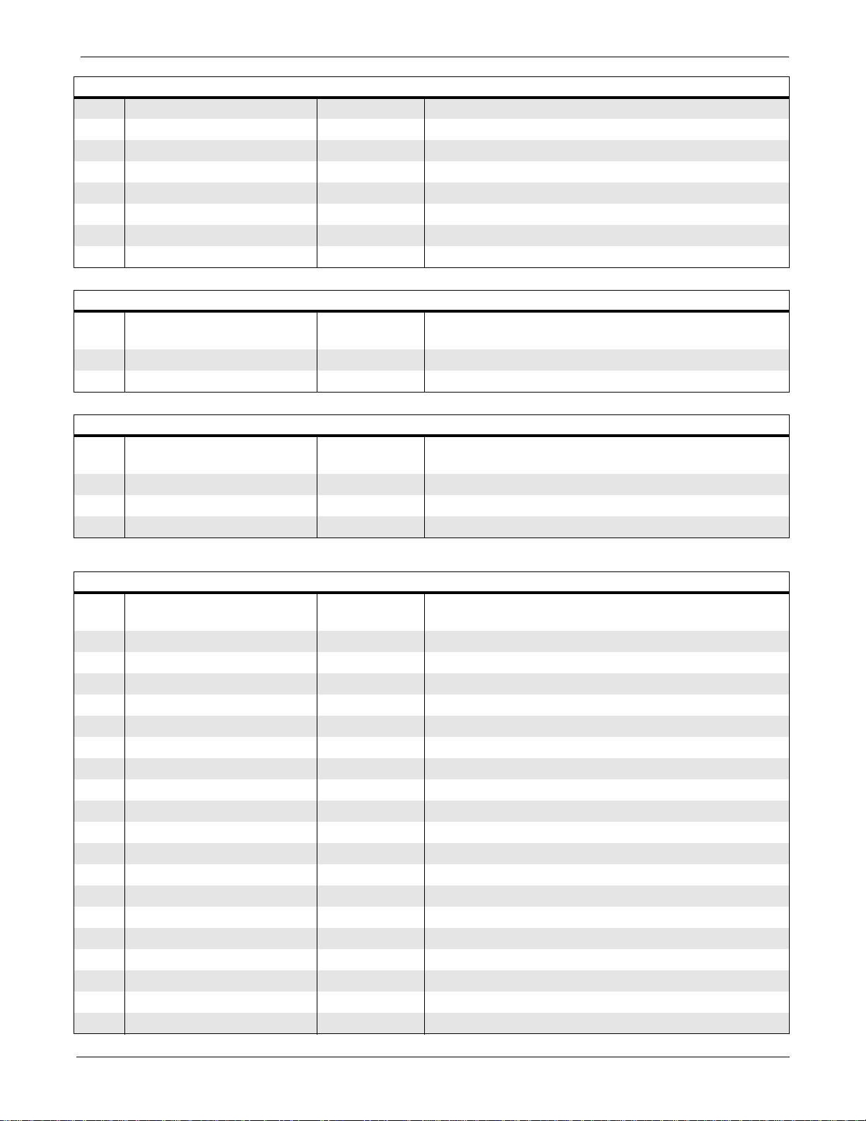
Table 2-4. Connector J3 (26-Pin EL Display Power Connector)
19 VidL0 O Video data bit, lower half of display
20 GND I +5 V power return
21 VidL1 O Video data bit, lower half of display
22 GND I +5 V power return
23 VidL2 O Video data bit, lower half of display
24 GND I +5 V power return
25 VidL3 O Video data bit, lower half of display
26 GND I +5 V power return
Table 2-5. Connector J4 (2-Pin Audio Speaker Connector)
Pin Name
Input/
Output
Description
1 Speaker + O Speaker output
2 Speaker - I Speaker input
Table 2-6. Connector J5 (3-Pin NBP Subsystem Pump Connector)
Pin Name
Input/
Output
Description
1 +V_PUMP O +12 V supplied to pump
2 PUMP_DRV I Pump drive
3 NC
Table 2-7. Connector J6 (96-Pin Option Board Interface Connector)
Pin Name
Input/
Output
Description
A1 +5 O +5 V power to option board
A2 SPARE1_I/O I/O Processor board spare I/O
A3 SPARE2_I/O I/O Processor board spare I/O
A4 OPT_BRD_IRQ5* I Interrupt from option board
A5 OPT_BRD_AVAIL* I Option board available
A6 AVEC*/IACK5* I/O Processor acknowledge
A7 ETCO2_TXD O ETCO2 transmit
A8 STARS_TXD O STARS transmit
A9 DSACK1* I Data strobe acknowledge
A10 DSACK0* I Data strobe acknowledge
A11 GND I +5 V power return
A12 SIZE1 O Processor bus site to transfer
A13 GND I +5 V power return
A14 SIZE0 O Processor bus site to transfer
A15 GND I +5 V power return
A16 AS* O Processor address strobe
A17 GND I +5 V power return
A18 DS* O Processor data strobe
A19 GND I +5 V power return
2-14
Eagle 3000 Patient Monitor
415397-038
Revision A
Page 33

UPPER LEVEL OVERVIEW: PCB Connectors PN 800772-002A
Table 2-7. Connector J6 (96-Pin Option Board Interface Connector)
A20 OE* O Processor read strobe
A21 GND I +5 V power return
A22 R/W* O Processor read/write strobe
A23 GND I +5 V power return
A24 WE1* O Processor word write strobe
A25 GND I +5 V power return
A26 WE0* O Processor byte write strobe
A27 GND I +5 V power return
A28 NC
A29 GND I +12 V power return
A30 GND I +12 V power return
A31 +12 O +12 V power to option board
A32 +12 O +12 V power to option board
B1 +5 O +5 V power to option board
B2 OPT_TP_RX- O Ethernet twisted pair RX-
B3 OPT_TP_RX+ O Ethernet twisted pair RX+
B4 MARKER_IN_IRQ4 I Processor interrupt from MARKER_IN
B5 BOOT_SELECT* I Boot source
B6 RESETH* O Processor hard reset
B7 ETCO2_RXD I ETCO2 receive
B8 STARS_RXD I STARS receive
B9 A1 O Processor address signal
B10 A3 O Processor address signal
B11 A5 O Processor address signal
B12 A7 O Processor address signal
B13 A9 O Processor address signal
B14 A11 O Processor address signal
B15 A13 O Processor address signal
B16 A15 O Processor address signal
B17 A17 O Processor address signal
B18 A19 O Processor address signal
B19 A21 O Processor address signal
B20 A23 O Processor address signal
B21 D17 I/O Processor data signal
B22 D19 I/O Processor data signal
B23 D21 I/O Processor data signal
B24 D23 I/O Processor data signal
B25 D25 I/O Processor data signal
B26 D27 I/O Processor data signal
B27 D29 I/O Processor data signal
B28 D31 I/O Processor data signal
B29 GND I +12 V power return
B30 GND I +12 V power return
B31 +12 O +12 V power to option board
B32 +12 O +12 V power to option board
Revision A
Eagle 3000 Patient Monitor
415397-038
2-15
Page 34
UPPER LEVEL OVERVIEW: PCB Connectors PN 800772-002A
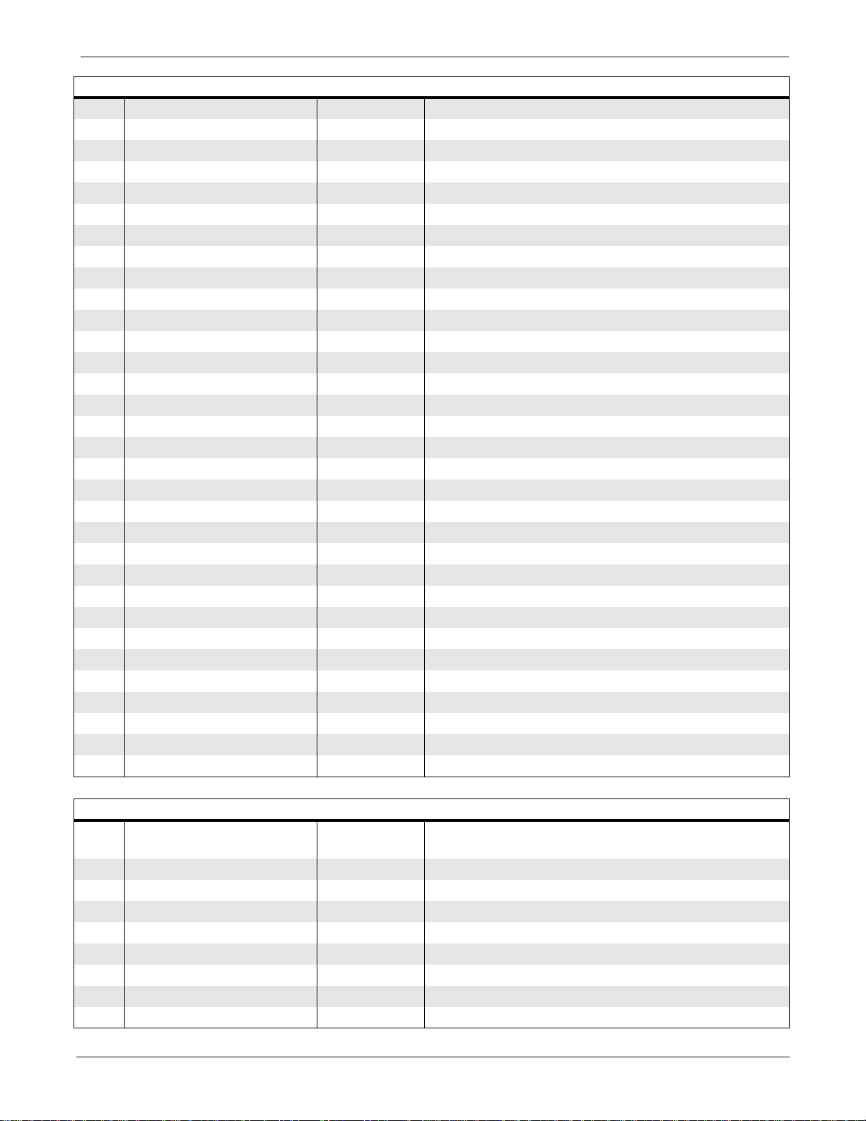
Table 2-7. Connector J6 (96-Pin Option Board Interface Connector)
C1 +5 O +5 V power to option board
C2 OPT_TP_TX+ O Ethernet twisted pair TX-
C3 OPT_TP_TX- O Ethernet twisted pair TX+
C4 OPT_BRD_IRQ2* I Processor interrupt
C5 OPT_BRDCS* O Processor chip select — option board
C6 FLASH_WE1* O Option board write stroke
C7 ETCO2_IRQ3* I ETCO2 interrupt
C8 STARS_SERVICE* O STARS service mode
C9 A0 O Processor address signal
C10 A2 O Processor address signal
C11 A4 O Processor address signal
C12 A6 O Processor address signal
C13 A8 O Processor address signal
C14 A10 O Processor address signal
C15 A12 O Processor address signal
C16 A14 O Processor address signal
C17 A16 O Processor address signal
C18 A18 O Processor address signal
C19 A20 O Processor address signal
C20 A22 O Processor address signal
C21 D16 I/O Processor data signal
C22 D18 I/O Processor data signal
C23 D20 I/O Processor data signal
C24 D22 I/O Processor data signal
C25 D24 I/O Processor data signal
C26 D26 I/O Processor data signal
C27 D28 I/O Processor data signal
C28 D30 I/O Processor data signal
C29 GND I +12 V power return
C30 GND I +12 V power return
C31 +12 O +12 V power to option board
C32 +12 O +12 V power to option board
Table 2-8. Connector J7 (8-Pin Front Panel User Interface Connection)
Pin Name
Input/
Output
Description
1 GND I +5 V power return
2 GND I +5 V power return
3 +5 O +5 V power to front panel LED
4 DISPLAY_ON/OFF* I User interface key
5 NBP_GO/STOP* I User interface key
6 BP_ZERO_ALL* I User interface key
7 SILENCE_ALARM* I User interface key
8 GRAPH_GO/STOP* I User interface key
2-16
Eagle 3000 Patient Monitor
415397-038
Revision A
Page 35
UPPER LEVEL OVERVIEW: PCB Connectors PN 800772-002A
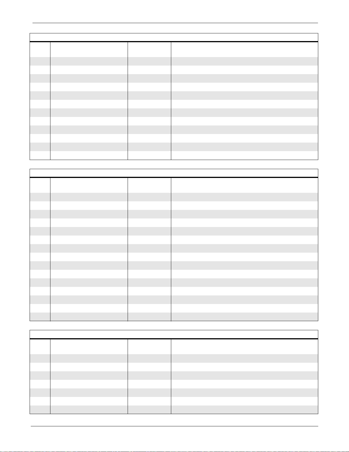
Table 2-9. Connector J8 (12-Pin Data Acquisition System Connector)
Pin Name
Input/
Output
Description
1 DAS_TXD O Serial data out to DAS
2 GND I Common power return
3 DAS_RXD I Serial data in from DAS
4 GND I Common power return
5 DAS_RESET* O To DAS
6 GND I Common power return
7 +12 O +12 V power to DAS
8 GND I Common power return
9 +12 O +12 V power to DAS
10 GND I Common power return
11 +5 O +5 V power to DAS
12 GND I Common power return
Table 2-10. Connector J9 (15-Pin Ethernet Communication Connector)
Pin Name
Input/
Output
Description
1 GND I Chassis ground
2 AVI_CLSN+ I Collision presence +
3 AVI_TX+ O Transmit data +
4 GND I Chassis ground
5 AVI_RX+ I Receive data +
6 GND I Common power return
7 NC
8 GND I Chassis ground
9 AVI_CLSN- I Collision presence 10 AVI_TX- O Transmit data 11 GND I Chassis ground
12 AVI_RX- I Receive data 13 +12 O +12 V power supply
14 GND I Chassis ground
15 NC
Table 2-11. Connector J10 (9-Pin Asynchronous Communication Connector)
Pin Name
Input/
Output
Description
1 ASYNC_RX+ I Receive data + from peripheral device
2NC
3 ASYNC_RX- I Receive data - from peripheral device
4 +12 O +12 V power out
5 ASYNC_TX- O Transmit data - to peripheral device
6 +12 +12 V power out
7 NC
Revision A
Eagle 3000 Patient Monitor
415397-038
2-17
Page 36
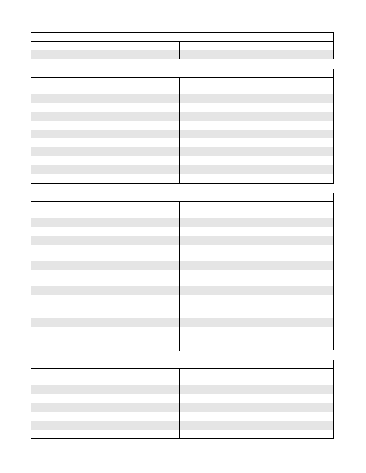
UPPER LEVEL OVERVIEW: PCB Connectors PN 800772-002A
Table 2-11. Connector J10 (9-Pin Asynchronous Communication Connector)
8 GND I Common power return
9 ASYNC_TX+ O Transmit data + to peripheral device
Table 2-12. Connector J11 (10-Pin NBP Subsystem Manifold Connector)
Pin Name
Input/
Output
Description
1 VAL1_DRV O Valve 1 (0.06" diameter) low side drive
2NC
3 NC
4 +12V_VALVE O Switched +12 V supplied to valve 1
5 NC
6NC
7 +12V_VALVE O Valve 0 (0.03" diameter) low side drive
8NC
9 NC
10 VAL0_DRV O Switched +12 V supplied to valve 0
Table 2-13. Connector J12 (10-Pin Background Debug Mode Connector)
Pin Name
Input/
Output
Description
1 DS* O Data strobe active low output
2 BERR* I Bus error active low input
3 GND I +5 V power return
4 BKPT/DSCLK I Breakpoint active low input initiates a hardware
breakpoint
5 GND I +5 V power return
6 FREEZE/CONFIGZ O Freeze active high output acknowledges a
breakpoint
7 RESETH* I/O Reset active low bi-directional
8 IFETCH/DSI O
Instruction fetch output for normal mode
instruction activity;
I
Data serial in for background mode
9 +5 O +5 V power
10 IPIPE/DSO O
Instruction pipe output for normal mode
instruction activity;
O
Data serial output for background mode
Table 2-14. Connector J25 (6-Pin Trim Knob Connector)
Pin Name
Input/
Output
Description
1 GND I +5 V power return
2 GND I +5 V power return
3 TRIM_PUSH I Trim Knob push select
4 TRIM_1 I Trim Knob rotary select
5 TRIM_0 I Trim Knob rotary select
6 +5 O +5 V power
2-18
Eagle 3000 Patient Monitor
415397-038
Revision A
Page 37
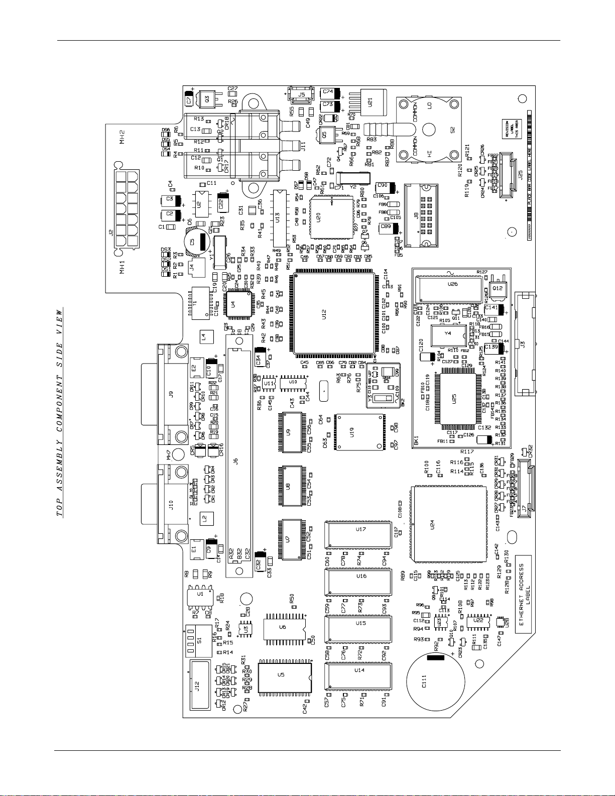
UPPER LEVEL OVERVIEW: Parts Location Diagram PN 800772-002A
Parts Location Diagram PN 800772-002A
Page 1 of 2
Revision A
Eagle 3000 Patient Monitor
415397-038
2-19
Page 38
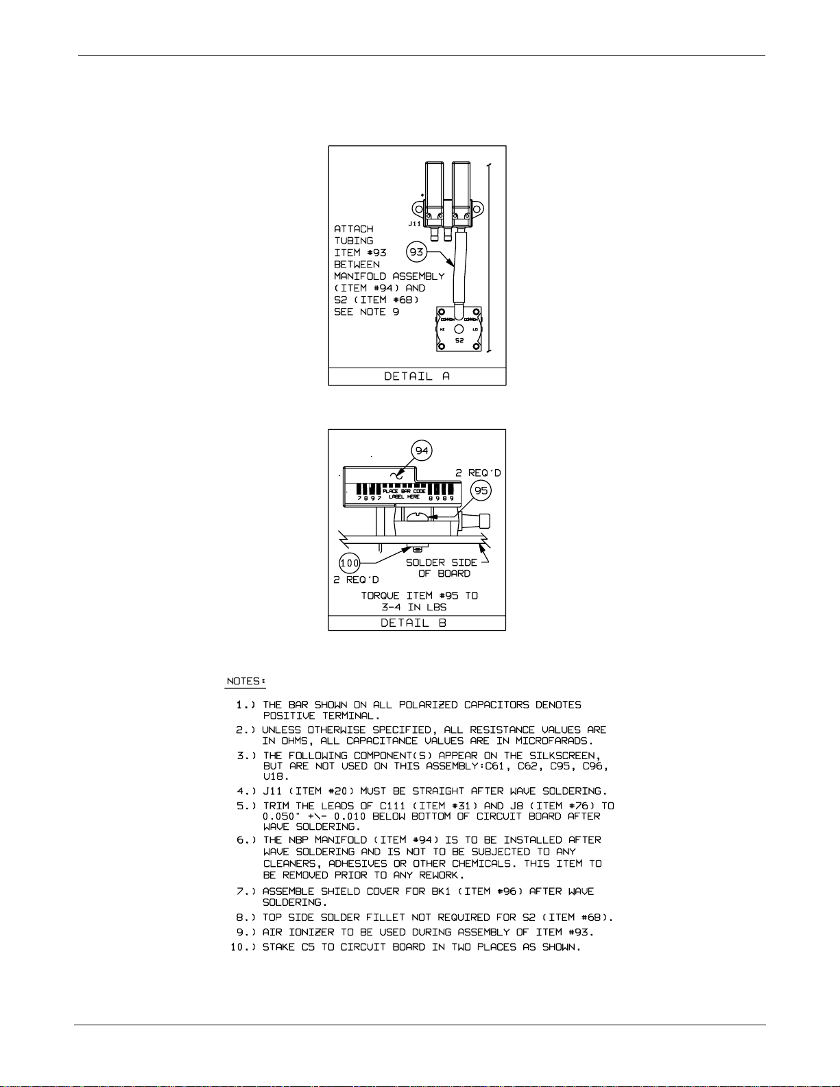
Page 2 of 2
UPPER LEVEL OVERVIEW: Parts Location Diagram PN 800772-002A
2-20
Eagle 3000 Patient Monitor
415397-038
Revision A
Page 39
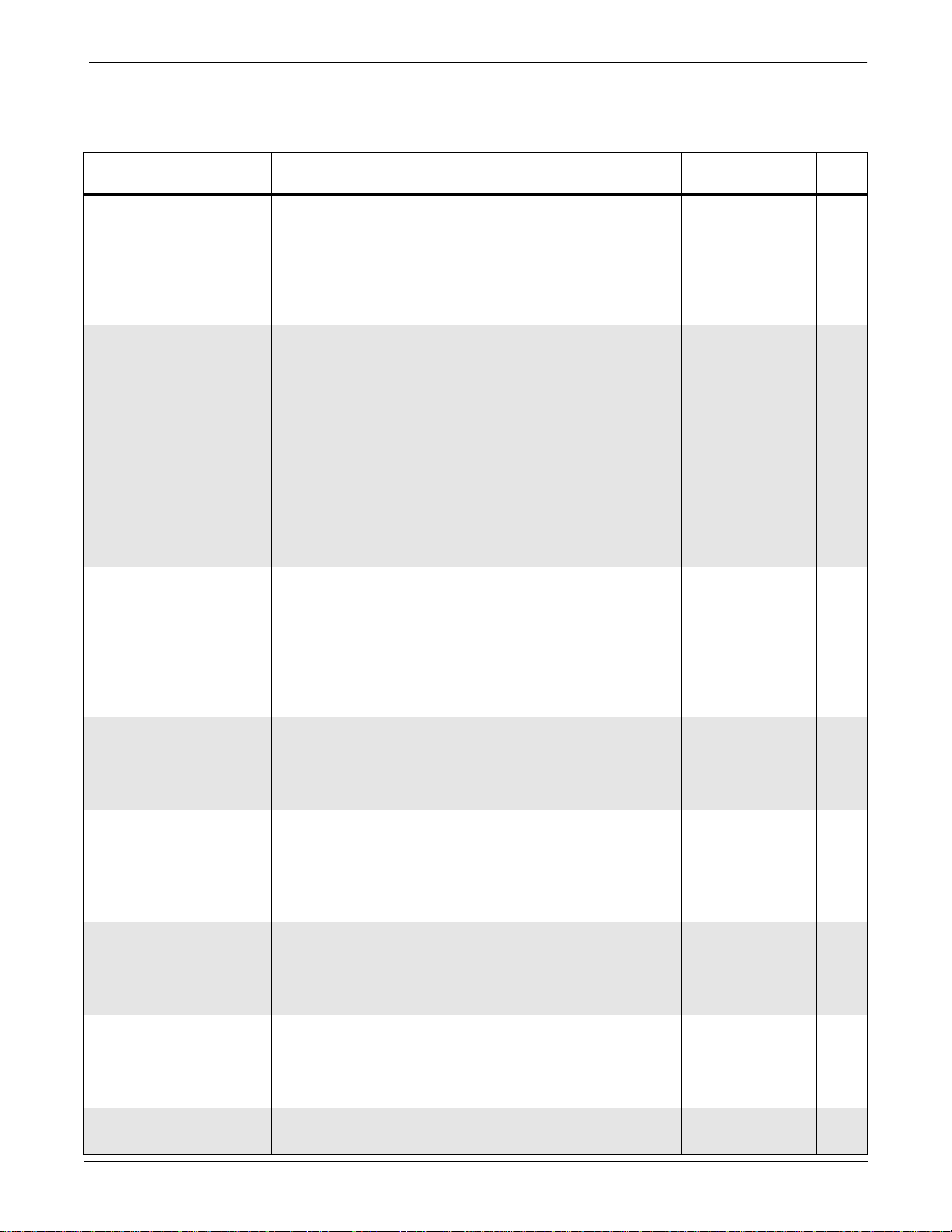
UPPER LEVEL OVERVIEW: Parts List PN 800772-002A
Parts List PN 800772-002A
Reference
Designation
BK1 Shield, Fence 415325-001 1
BK2 Shield, Tin 415589-001 1
C1, 6, 12-14, 17, 27,
33, 49, 81, 128, 140
C2, 3, 9, 10, 22, 32,
34, 89, 90, 139, 141
C4, 8, 18, 23, 24, 28-
30, 35-43, 45-48, 5060, 63-70, 75-80, 8284, 85-87, 91-94, 97,
100-104, 106-108,
112, 114-116, 119,
121, 122, 125-127,
131, 133, 135, 136,
138, 142-147
C5 Cap, Al Radial, 470uF, 20%, 25V 1259-471 1
C7, 120, 132 Cap, Tant, 4.7
C11, 21 Cap, Cer, 0.047
C15, 16, 44, 88, 98,
105, 113, 117, 118,
123, 124, 129, 130,
134, 137
C19, 20 Cap, Cer, 68pF, 5%, 50V, SM 1152-680 2
C25 Cap, Cer, 3900pF, 5%, 50V, SM 1182-564 1
C26 Cap, Cer, 0.039
C31 Cap, Cer, 0.22
C71, 72, 109, 110 Cap, Cer, 22pF, 5%, 50V, SM 1181-220 4
C73, 74 Cap, Tant, 22
C99 Cap, Cer, 0.39
C111 Cap, 1F, -20/+80%, 5.5V 402341-001 1
CR1-4, 6-15, 17-21,
24-32
CR5, 16 Transorb, 15V, 5%, 600W SM6T15A 403188-001 2
CR22 Diode, Schottky, Barrier, 1A, 40V, SM MBRS140T3 403187-001 1
CR23 Diode, SM FDSO1503 2414-001 1
DS1, 4, 8 Light-Emitting Diode, Green, SM 1206 414417-004 3
DS2, 5 Light-Emitting Diode, Yellow, SM 1206 414417-003 2
DS3, 6, 7 Light-Emitting Diode, Red, SM 1206 414417-002 3
E1, 2 Surge Current Protector, 750mA 1914-075 2
FB1-7, 10-14, 17-29 Ferrite Bead BLM11A20 414061-001 1
FB8, 9, 15, 16 Ferrite Bead, SM 403800-002 4
J2 Connector, Receptacle, Vertical Minifit, BMI, 14-Pin 413799-001 1
J3 Connector, PC Header, Vertical, 4-Wall, Low Profile 17030-026 1
J4 Connector, Header, 2-Pin 17043-202 1
Cap, Cer, 0.1
Cap, Tant, 10
Cap, Cer, 0.1
Cap, Cer, 0.1
Diode Pair, Series, SM D7000 2013-201 28
µ
µ
µ
Description Part Number Qty
F, 20%, 50V 404370-001 12
µ
F, 20%, 25V, SM 1152-106 11
F, 5%, 16V 411575-002 86
µ
F, 20%, 20V, SM 402004-001 3
µ
F, 5%, 50V, SM 1182-824 2
F, 5%, 50V, SM 411575-012 15
µ
F, 5%, 50V, SM 1182-393 1
µ
F, 5%, 50V, SM 1182-224 1
µ
F, 10%, 25V, SM 407653-001 2
µ
F, 5%, 50V, SM 413751-001 1
Revision A
Eagle 3000 Patient Monitor
415397-038
2-21
Page 40
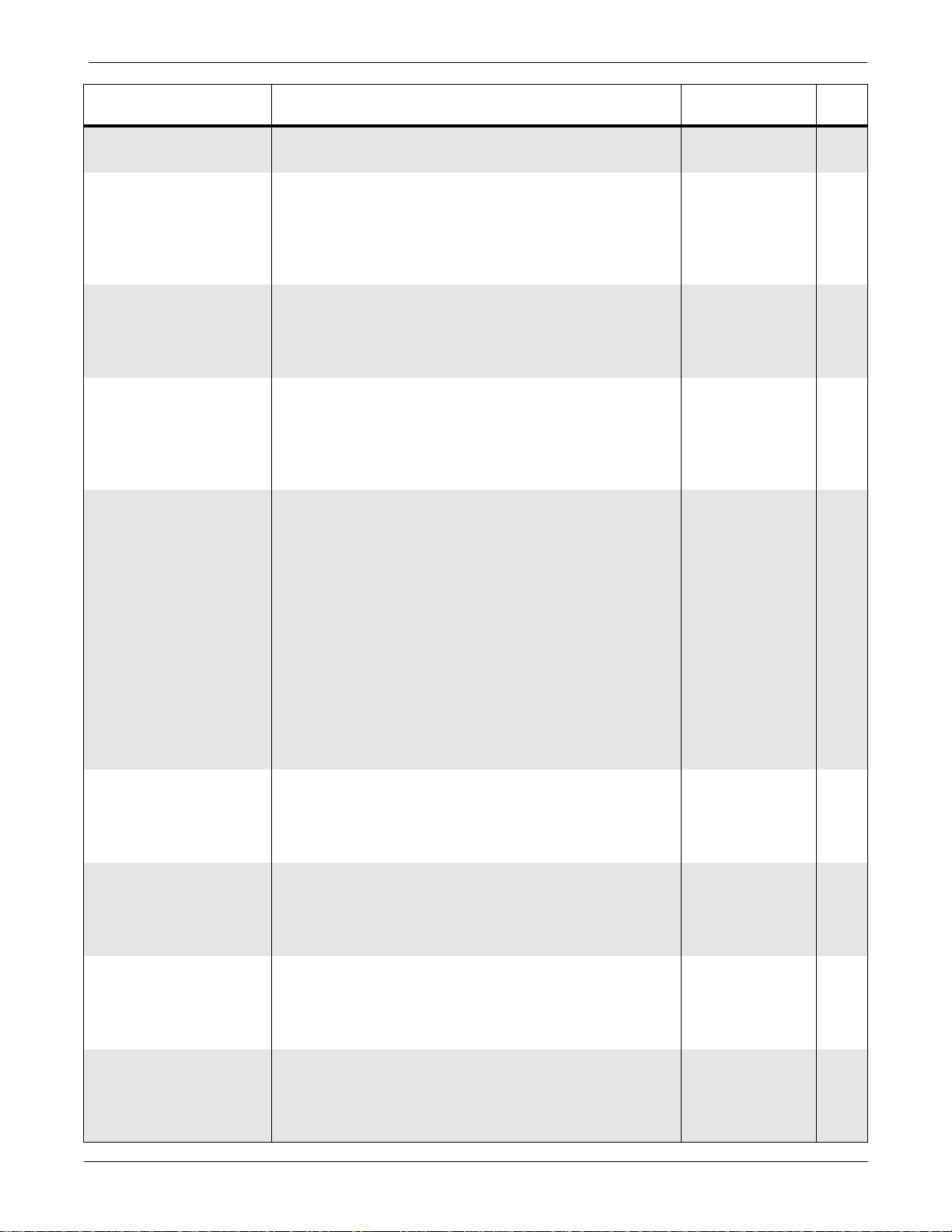
UPPER LEVEL OVERVIEW: Parts List PN 800772-002A
Reference
Designation
Description Part Number Qty
J5 Connector, Header, Vertical, 3-Pin 17043-203 1
J6 Connector, DIN, Vertical, 96-Pin 415358-001 1
J7 Connector, Header, Vertical, Single Row, 8-Pin 415161-002 1
J8 Connector, PC Header, Vertical, 12-Pin 414032-001 1
J9 Connector, Receptacle, Right Angle, PC, 15-Pin 17026-315 1
J10 Connector, Receptacle, Right Angle, 9-Pin with
17026-209 1
Rivets
J11 Connector, Receptacle, PC, 10-Pin, Vertical 1781-010 1
J12 Connecter, PC Header, Vertical, 10-Pin 17030-010 1
J25 Connector, Header, Vertical, Single Row, 6-Pin 415161-001 1
L2, 4 Coil, Choke, 1000
Ω
, 1.5A, SM 415233-001 2
Q1, 2, 4, 6, 7, 9, 11 Transistor, NPN, SM T3904 2511-001 7
Q3, 12 Transistor, HEXFET, P-Channel, 25W, SM
406513-001 2
IRFR9010TR
Q5 Transistor, MOS-FET, N-Channel, SM 25N05 407659-001 1
Q10 Transistor, PNP, SM T3906 2511-101 1
R1-7, 11, 12, 28, 37,
Res, Cer, 1K, 1%, 1/16W, SM 410334-008 26
52, 54, 56, 65, 68, 79,
80, 86-88, 90, 99,
108, 109, 130
R8, 9 Res, Cer, 49.9
R10, 13, 63, 114,
Res, Cer, 49.9
Ω
, 1%, 1/8W, SM 1082-799 2
Ω
, 1%, 1/16W, SM 410334-040 15
131-141
R14-18, 24, 26, 27,
Res, Cer, 10K, 1%, 1/16W, SM 410334-013 76
29-34, 36, 38-40, 4251, 53, 57-60, 64, 66,
67, 69-78, 89, 91, 92,
97, 98, 100-103, 105107, 110, 112, 113,
115-129
R19, 20, 21, 22 Res, 39.2
R23, 55 Res, Cer, 10
Ω
, 1%, 1/8W, SM 1082-826 4
Ω
, 1%, 1/8W, SM 1082-786 2
R25 Res, Cer, 287K, 1%, 1/16W, SM 410334-117 1
R35 Res, Cer, 453K, 1%, 1/16W, SM 410334-116 1
R41 Res, Cer, 549K, 1%, 1/16W, SM 410334-118 1
R61, 96 Res, Cer, 1.0M, 1%, 1/16W, SM 410334-120 2
R62 Res, Cer, 2K, 1%, 1/16W, SM 410334-009 1
R81, 93 Res, Cer, 3.01K, 1%, 1/16W, SM 410334-018 2
R82 Res, Cer, 6.34K, 1%, 1/16W, SM 410334-048 1
R83 Res, Cer, 2.74K, 1%, SM 410334-078 1
R84 Res, Cer, 10M, 5%, 1/16W, SM 411723-003 1
R85 Res, Cer, 332K, 1%, 1/16W, SM 410334-115 1
R94 Res, Cer, 649K, 1%, 1/16W, SM 410334-119 1
R95 Res, Cer, 20M, 1%, 1/8W, SM 1081-510 1
R104 Res, Cer, 10
R111 Res, Cer, 200
Ω
, 1%, 1/16W, SM 410334-031 1
Ω
, 1%, 1/8W, SM 1082-762 1
2-22
Eagle 3000 Patient Monitor
415397-038
Revision A
Page 41
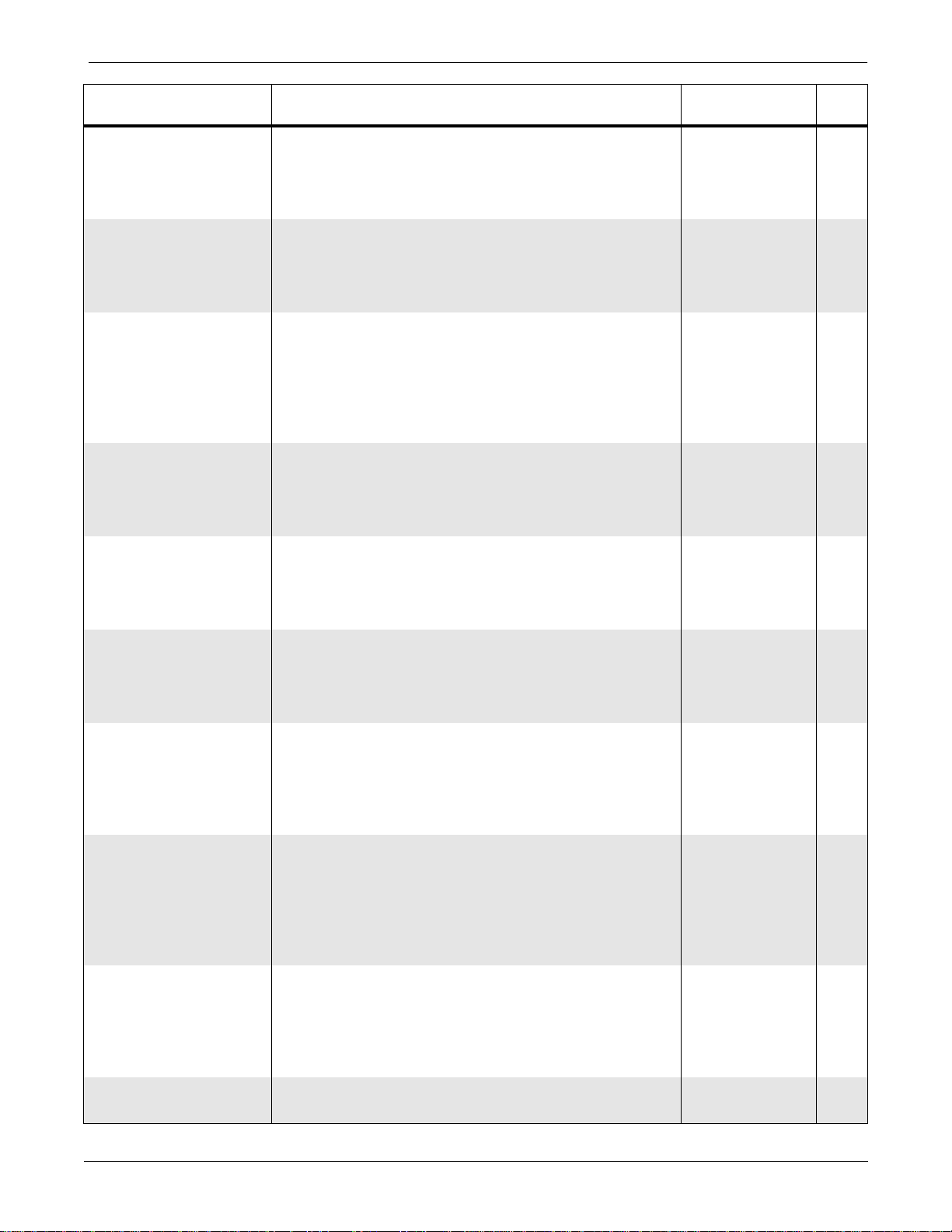
UPPER LEVEL OVERVIEW: Parts List PN 800772-002A
Reference
Designation
Description Part Number Qty
S1 Switch, DIP, SPST, 4-Position 415387-001 1
S2 Switch, Dual Pressure Sensor, PCB 413482-002 1
T1 Transformer, Ethernet Isolation, SM 407146-001 1
U1 Isolator, Optically-Coupled, SM 2602 407164-001 1
U2 Power Ampl, Audio LM386N 3102-386 1
U3 Transceiver, Low-Power ADM485 414085-001 1
U4 Ethernet Serial Interface Adapter, SM 68160 413696-001 1
U5 RAM, Static, 128K x 8-Bit, 70nS, SM 628128 406255-002 1
U6 Real-Time Clock/Calendar, 8-Bit, 85nS, SM RTC-
408831-001 1
64613
U7 Transceiver, Bus, Octal ACTQ16245 410523-001 1
U8, 9 Buffer/Line Driver, Octal, SM ACTQ16244 410522-001 2
U10 Flip Flop, Positive-Edge-Triggered, Type D, Dual,
401433-001 1
SM ACT74
U11 EEPROM, Serial, 16K x 8-Bit, CMOS AT24C16N 414007-002 1
U12 Microprocessor, 25mHz, SM 68EN360 413698-003 1
U13 Sound Generator, 3-Channel YMZ284 413704-001 1
U14-17, 26 RAM, Dynamic, 256K x 16-Bit TC514260BJ 3207-811 5
U19 EEPROM, Flash, 1M x 16-Bit, 70nS, SM 28F016 413703-001 1
U20 NBP Interface, FPGA 414521-001 1
U21 Volt Rgltr, Adj LM2941 403609-002 1
U22 NAND Gate, 2-Input, Quad, SM AC00 400813-001 1
U23 Microprocessor, Supervisor, SM MAX802L 416617-001 1
U24 EPLD, Programmed, Main Processor PCB 415297-001 1
U25 VGA Controller, Flat Panel, 100-Pin F65510 414290-001 1
U27 Inverter, Hex, CMOS, SM TC7SHUO4FU 416584-001 1
U28 Buffer, Dual, CMOS, 3-State Output, Quad
416618-001 1
TC7W126
Y1 Crystal, 20MHz 408829-001 1
Y2 Crystal, 4.194304MHz, SM 407658-001 1
Y3 Crystal, 31.2kHz, SM 408946-001 1
Y4 Crystal Oscillator, 45.0-MHz, SM 404987-003 1
– Tubing, Silastic (item 93 for manifold valve
401582-001 AR
assembly)
– Manifold Valve Assembly 414621-001 1
– Screw, BDGH, Phillips, 6-32 x 3/8 (item 95 for
45074-612 2
manifold valve assembly)
– Shield, Cover (item 96 for BK1) 415325-002 1
– Nut, PEM, 6-32 (item 100 for manifold valve
414292-001 2
assembly)
– Label, Model/Serial Number 404525-120 1
– Adhesive/Sealant (item 102 for C5) 414240-001 AR
– Circuit Board 800773-002A 1
– Schematic Diagram SD800772-002A 1
Revision A
Eagle 3000 Patient Monitor
415397-038
2-23
Page 42

UPPER LEVEL OVERVIEW: Parts List PN 800772-002A
2-24
Eagle 3000 Patient Monitor
415397-038
Revision A
Page 43
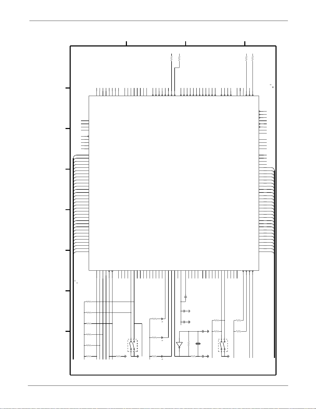
UPPER LEVEL OVERVIEW: Schematic Diagram PN SD800772-002A
Schematic Diagram PN SD800772-002A
Page 1 of 18
NC1
NC1
NC1
NC1
NC1
PRTY3
PRTY2
PRTY1
PRTY0
D31
D30
D29
D28
D27
D26
D25
D24
D23
D22
D21
D20
D19
D18
D17
D16
D15
D14
D13
D12
D11
D10
6
5
4
3
2
D
9
D
8
D
7
D
6
D
5
D
4
D
3
D
2
D
1
D
0
D
DAS_RXD
DAS_TXD
RS422_RXD
ETH_TXD
TXD1/PA1
RXD2/PA2
TXD2/PA3
RXD3/PA4
RS422_TXD
STARS_RXD
TXD3/PA5
RXD4/PA6
ETH_RXD
404344454648495051535455565859
RXD1/PA0
129
N
C
192
N
C
209
N
C
214
N
C
231
PERR*
198
PARITY3
199
PARITY2
202
PARITY1
203
PARITY0
105
D31
104
D30
103
D29
101
D28
100
D27
9
9
D26
9
7
D25
9
6
D24
9
5
D23
9
3
D22
9
2
D21
9
1
D20
8
6
D19
8
5
D18
8
4
D17
8
2
D16
8
1
D15
7
9
D14
7
8
D13
7
7
D12
7
5
D11
7
4
D10
7
3
D
9
7
2
D
8
7
1
D
7
6
9
D
6
6
8
D
5
6
6
D
4
6
5
D
3
6
4
D
2
6
2
D
1
6
1
D
0
ETH_RXD_CLK
ETH_TXD_CLK
STARS_TXD
TXD4/PA7
CLK1/PA8
CLK2/PA9
PCB REV BIT 0
SPARE1_I/O
OPT_BRD_AVAIL*
WD_STROBE
GND
CLK3/PA10
CLK4/PA11
CLK5/PA12
CLK6/PA13
240 PIN CQFP
U12
68EN360Q
PCB REV BIT 1
PCB REV BIT 2
GND
AVEC*/IACK5*
+5
233
60
AVEC*
CLK7/PA14
CLK8/PA15
C
R57
RTC_IRQ1*
ETCO2_IRQ3*
MARK_IN_IRQ4*
OPT_BRD_IRQ2*
OPT_BRD_IRQ5*
24032
2211222
IRQ1*
IRQ2*
IRQ3*
IRQ4*
IRQ5*
10K
IRQ6*
+5
170
10K
R91
IRQ7*
+5
BOOT_CS0*
DRAM_RAS1*
DRAM_RAS2*
180
179
178
177
CSO*
CS1*
CS2*
SRAM_CS3*
FLASH_CS4*
PLD_CS6*
PLD_CS5*
172
174
173
CS3*
CS4*
CS5*
CS6*
B
CAS0*
CAS1*
CAS2*
CAS3*
OPT_BRD_CS7*
171
182
183
185
187
CS7*
CAS0*
CAS1*
CAS2*
CAS3*
NC11
BKPT/DSCLK
IFETCH/DSI
IPIPE0/DSO
207
204
213
224
IPIPE0*/DSO
IFETCH*/DSI
BKPT*/DSCLK
IPIPE1*/RAS1DD
A31/WE0
A30/WE1
A29/WE2
A28/WE3
+5
10K
R60
10K
R64
NC10
FREEZE/CONFG2
CNFG1
CNFG0
218
219
234
210
188
BG*
BGACK*
OE*
DS*
RMC*/CNFG0
AS*
FREEZE/CNFG2
BCLR0*/CNFG1
R/W
DSACK1*
DSACK0*
SIZE1
SIZE0
FC3
FC2
FC1
FC0
A27
A26
A25
A24
A23
A22
A21
A20
A19
A18
A17
A16
A15
A14
A13
A12
A11
A10
215
BR*
A
+5
212
OE*
189
DS*
205
AS*
191
R/W
196
194
113
114
108
109
110
112
116
117
119
120
130
131
132
134
135
136
138
139
140
142
143
144
145
146
148
149
151
152
154
155
158
159
161
162
164
165
167
168
DK1
DK0
SIZ
SIZ
NC9
NC8
NC7
NC6
WE0
WE1
WE2
WE3
A27
A26
A25
A24
A23
A22
A21
A20
A19
A18
A17
A16
A15
A14
A13
A12
A11
A10
A
A
A
A
A
A
A
A
A
A
*
*
*
1
0
*
*
*
*
9
8
7
6
5
4
3
2
1
0
*
*
*
*
*
A
9
A
8
A
7
A
6
A
5
A
4
A
3
A
2
A
1
A
0
Revision A
TCLOCK
TMODE SELECT
TDATA IN
227
228
229
230
R16
10K
R33
10K
R17
10K
R49
10K
R48
10K
8 76543 21
D31-D0
R53
10K
+5
TCK
TMS
TDI
TDATA OUT
TRESET*
TRI-STATE*
SPISEL*/PB0
SPICLK/PB1
SPIMOSI/PB2
SPIMISO/PB3
PB4
PB5
SMRXD1/PB7
SMTXD1/PB6
1920212223242527282930323334353738
226
169
NC1
NC2
NC3
NC4
IRDA_TX
IRDA_RX
SOFTWARE UPDATE*
WATCH DOG ENABLE
8
7
1
2
S1
1
2
1K
WD_ENABLE
TDO
TRST*
TRIS*
R56
Eagle 3000 Patient Monitor
PB8
PB9
SMTXD2/PB10
SMRXD2/PB11
RTS1*/PB12
PB13
EE_CLK
EE_DATA
ETH_LOOP
ETCO2_TXD
ETCO2_RXD
ETH_TX_EN
DS6
R6
1K
DS5
R5
1K
DIAGNOSTIC LEDS
DS4
R4
1K
+5
415397-038
PB16
PB15
PB14
39
CAP_READ
RED
AMBER
U27
GREEN
PB17
EXTAL
XTAL
124
125
NC68
TCU04
42
VCCSYN
121
122
5%
C99
C88
C87
+5
R84
XFC
MODCLK0
126
MODCLK0
.39
50V
.01
.1
10M
CLK1 OUT
CLK2 OUT
MODCLK1
90
87
127
NC5
MODCLK1
SYSTEM_CLK
5% 50V
5%
R85
332K
PC0
PC1
PC2
45689
D_TRIM_0
D_TRIM_1
D_TRIM_PUSH*
C109
22pF
50V
5%
Y3
31.2KHz
C110
22pF
50V
5%
PC3
CTS1*/PC4
CD1*/PC5
PC6
PC7
PC8
PC9
10111314151618
UNUSED
UNUSED
ETH_CLSN
ETH_RX_EN
D_DSPL_ON/OFF*
+5
R14
R15
S1
10K
10K
6
5
3
4
3
4
D_SILENCE_ALARM*
D_GRAPH_GO/STOP*
PC10
PC11
D_BP_ZERO_ALL*
+5
BERR*
RESETS*
RESETH*
HALT*
237
236
225
239
D_NBP_GO/STOP*
R52
1K
R47
10K
RESETH*
BERR*
A27-A0
2-25
Page 44
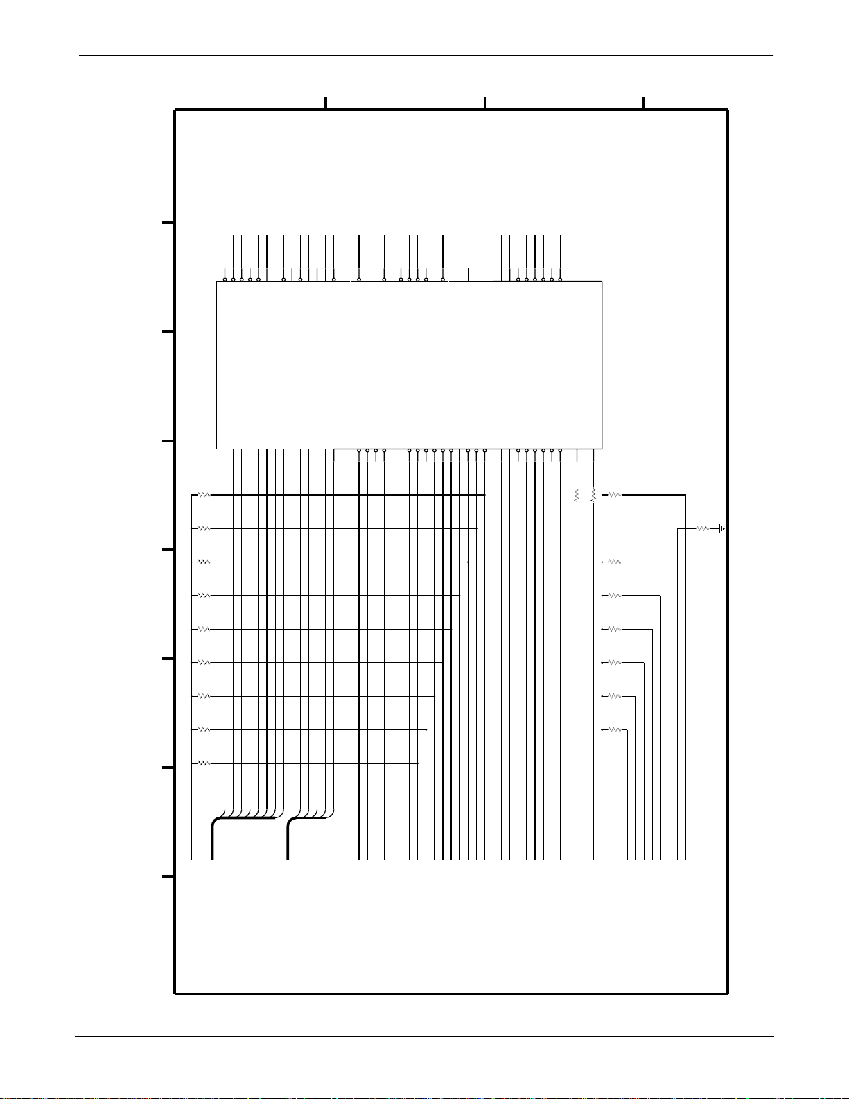
UPPER LEVEL OVERVIEW: Schematic Diagram PN SD800772-002A
Page 2 of 18
D
VIDEO_BHE*
VIDEO_IORD*
VIDEO_IOWR*
VIDEO_MEMRD*
58
VIDEO_BHE*
VIDEO_IORD*
VIDEO_IOWR*
VIDEO_MEMRD*
D7D6D5D4D3D2D1D0A20
U24
7128E
70717977737675
R30
10K
R99
1K
VIDEO_MEMWR*
VIDEO_RDY
DAS_RESET*
VIDEO_RESET
AUDIO_RESET*
40
6757566869
VIDEO_RDY
DAS_RESET*
VIDEO_RESET
AUDIO_RESET*
VIDEO_MEMWR*
4
74284
CAP_ENABLE
NBP_ENABLE
NBP_NORMAL_MODE*
FLASH_WP*
SPARE_OUTPUT
54
618446561
24
FLASH_WP*
CAP_ENABLE
NBP_ENABLE
SPARE_OUTPUT
NBP_NORMAL_MODE*
A18
A19
A17
A0
81
60
C
BOOT_SEL*
31
BOOT_SEL*
BOOT_CS0*
36
AUDIO_CS*
AUDIO_WR*
NBP_CS*
RTC_CS*
223363
RTC_CS*
NBP_CS*
AUDIO_WR*
RESETH*
AS*
DS*
1
28
30
FLASH_WE1*
45
FLASH_WE1*
R/W*
WE1*
WE0*
OPTION_BUS_EN*
64
12
AUDIO_CS*
OPTION_BUS_EN*
PLD_CS5*
PLD_CS6*
OPTION_BOARD_CS*
PB_RESET
5
46
3715292717142116233425204135623955
NC17
80
RESERVED I/O
SIZ0
DSACK1*
DSACK0*
BERR*
TRIM_0
TRIM_1
TRIM_PUSH*
11
TRIM_1
TRIM_0
TRIM_PUSH*
D_TRIM_0
D_TRIM_1
D_TRIM_PUSH*
8
B
GRAPH_GO/STOP*
SILENCE_ALARM*
BP_ZERO_ALL*
NBP_GO/STOP*
DISPLAY_ON/OFF*
4849505152910
BP_ZERO_ALL*
NBP_GO/STOP*
SILENCE_ALARM*
GRAPH_GO/STOP*
DISPLAY_ON/OFF*
D_GRAPH_GO/STOP*
D_NBP_GO/STOP*
D_DISPLAY_ON/OFF*
D_BP_ZERO_ALL*
D_SILENCE_ALARM*
AUDIO_CLK
49.9
R114
R63
83
49.9
SYSTEM_CLK
R40
10K
A
R65
1K
R109
1K
R89
10K
R103
10K
R113
10K
R112
10K
R31
10K
R122
10K
D31
D30
D29
D28
D27
D26
+5
D31-D0
8 76543 21
D25
D24
A27-A0
A20
A19
A18
A17
A0
PLD_CS5*
PLD_CS6*
BOOT_CS0*
OPT_BRD_CS*
DS*
AS*
RESETH*
PB_RESET
R/W*
WE1*
WE0*
SIZ0
DK1*
DK0*
BERR*
D_TRIM_0
D_TRIM_1
D_TRIM_PUSH*
D_GRAPH_GO/STOP*
D_SILENCE_ALARM*
AUDIO_CLK
SYSTEM_CLK
D_BP_ZERO_ALL*
D_NBP_GO/STOP*
D_DSPL_ON/OFF*
R28
1K
R86
1K
R90
1K
R76
10K
R75
10K
R58
10K
+5
OE*
WE2*
WE3*
CNFG1
MODCLK0
MODCLK1
FREEZE/CONFG2
CNFG0
2-26
Eagle 3000 Patient Monitor
415397-038
Revision A
Page 45
UPPER LEVEL
VERVIEW
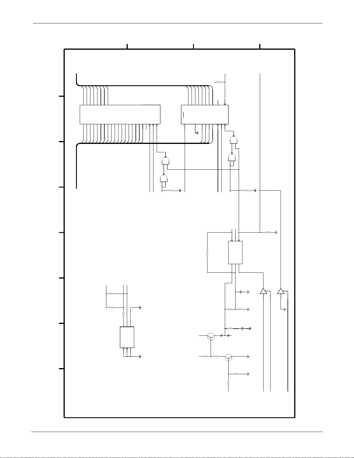
UPPER LEVEL OVERVIEW: Schematic Diagram PN SD800772-002A
hematic DiagramPN SD800772-002A
Page 3 of 18
D
C
B
A
D31-D0
D29
D28
D27
D26
D25
D24
3457890
1111112
0123456
DDDDDDD
U5
628128L
01234567891111111SC
AAAAAAAAAAAAAAAAACN
AAAAAAAAAAAAAAA
2109876576354831201
111
A0A1A2A3A4A5A6A7A8A9A10
A27-A0
D30
D31
1
2
7
D
0123456
22222
A11
A12
A13
A14
3
A15
A16
74AC00 POWERED BY +VBAT
R98
10K
1K
R108
RESETH*
R107
10K
RTC_IRQ1*
R50
10K
+
5
D31
D30
D29
D28
D27
D26
D25
D24
A3
567
A2A3A0
NC20
3
DOD1D2D3D4D5D6
1Hz
IRQ
CSOEWE
A0A1A2
8
201918
WE0*
OE*
U22
74AC00
U22
6
74AC00
4
5
3
1
2
RTC_CS*
+VBAT
CAP_READ
517
A1
1716151413111094
D7
2
WEOECS1
A
3
292422
NC19
A17
U22
74AC00
U22
OE*
WE0*
11
74AC00
12
13
8
9
10
R97
SRAM_CS3*
U6
10K
ST/STP
RTC-64613
2
+VBAT
NC
21
8 76543 21
PFO*
VOUT
5%
20M
R95
1/8W
+5
EE_DATA
EE_CLK
R36
10K
R38
10K
1K
R37
X24C16
U11
567
DATA
A0A1A2
123
CLK
TEST
+
5
+
5
R92
CR23
Q10
3906
2
3
1
1
10K
R93
3.01K
VBAT
MAX802L
U23
846
R94
649K
R111
200
FDS01503
2
3
Q9
3904
3
1
10K
R102
CAP_ENABLE
RESET*WDI
PFI
C112
.1
R96
1M
C111
1/8W,5%
+
NC1
8
2
R101
10K
1.0F
GOLD
CAP
5.5V
TC126
U28
26
-20/+80%
WD_STROBE
3
TC126
U28
1
5
WD_ENABLE
7
PB_RESET
2-26
Eagle 3000 Patient Monitor
415397-038
Revision A
Page 46
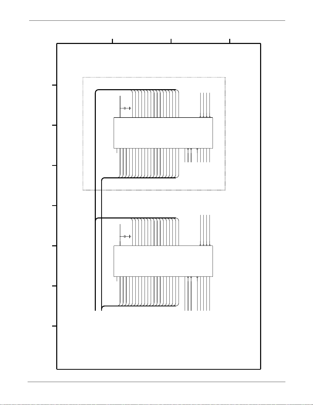
age 4 of 18
UPPER LEVEL OVERVIEW: Schematic Diagram PN SD800772-002A
D
C
B
A
D16
D17
D18
D19
D20
D21
C96
.01
5%
33
353840444649513436394145475052
15
D2D3D4D5D6
D0
VPP
A1A2A3A4A5A6A7
A0/BYTE SELECT
28F016
U18
322726252423222019181713121110
28
NC27
A1A2A3A5A4A6A7A8A9
+12 +12
15
VPP
D1
A8A9A10
A10
D16
D17
D18
D19
D20
D21
C98
.01
5%
33
353840444649513436394145475052
50V 50V
D0
D1
D2D3D4D5D6
D22
A11
D22
A11
D23
A12
D23
D7
A12
D7
D24
A13
D24
D8
A13
D8
D25
A14
D25
D9
A14
D9
D26
D27
D10
D11
A15
A16
865
A15
A16
D26
D27
D10
D11
D28
7
A17
D28
D12
A17
D12
D29
D13
A18
A18
D29
D13
D30
D14
A19
A19
D30
D14
D31
D15
A20
4
A20
D31
D15
31
RDY/BSY*
SIZE:8*/16
WRITE_PROTECT
PWRDWN
53
16
56
+5
NC28
RESETH*
FLASH_WP*
GND
OPT_OE*
FLASH_WE1*
FLASH_CS4*
14255
54
WE
OE
CE0
CE1
NC
NC
NC
NC
3
1
29
30
NC30
NC31
NC32
GND
OE*
FLASH_WE1*
MAIN_BRD_CS*
14255
54
WE
OE
CE0
CE1
NOT INSTALLED
Revision A
8 76543 21
D31-D0
A27-A0
A1A2A3A4A5A6A7
A0/BYTE SELECT
28F016
U19
322726252423222019181713121110
28
NC21
A1A2A3A5A4A6A7A8A9
A8A9A10
A10
Eagle 3000 Patient Monitor
415397-038
A11
A11
A12
A12
A13
A13
A14
A14
A15
A16
865
A15
A16
7
A17
A17
A18
A18
A19
A19
4
A20
A20
SIZE:8*/16
31
+5
RDY/BSY*
WRITE_PROTECT
PWRDWN
NC
1
53
16
56
GND GND
NC22
RESETH*
FLASH_WP*
3
NC
29
NC24
NC
30
NC25
NC
NC26
FLASH BANK 0 FLASH BANK 1
2-27
Page 47
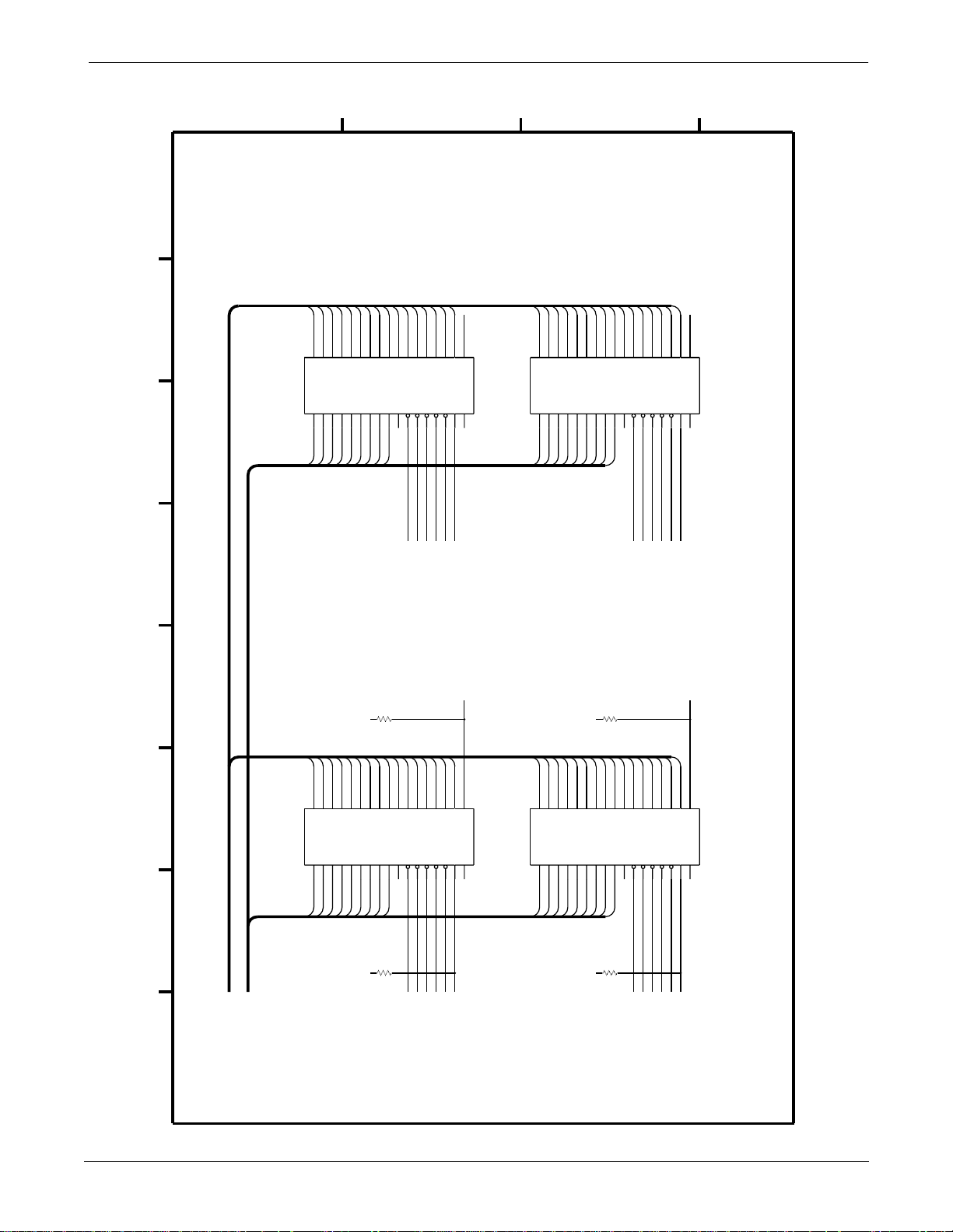
Page 5 of 18
UPPER LEVEL OVERVIEW: Schematic Diagram PN SD800772-002A
D
C
B
A
D0D1D2D3D4D5D6D7D8
23457891333333333
D0D1D2D3D4D5D6D7D8
A1A2A3A4A5A6A7A8RASOEWENCNC
A0
TC514260
U16
67892345654897312
11112222211222111
A2A3A4A5A6A7A8A9A10
D9
D10
012346789
D9
NC
NC37
R74
10K
+
5
D11
D12
D13
D14
D10
D11
D12
D13
D14
UCAS
LCAS
OE*
R/W*
CAS2*
CAS3*
DRAM_RAS2*
D15
D15
PRTY0
PRTY1
0
NC
NC38
PRTY1
D16
D17
D18
D19
D20
D21
D22
D23
D24
D25
D26
23457891333333333
D0D1D2D3D4D5D6D7D8
A1A2A3A4A5A6A7A8RASOEWENCNC
A0
TC514260
U14
67892345654897312
11112222211222111
A2A3A4A5A6A7A8A9A10
012346789
D9
D10
NC
NC39
R72
10K
+
5
D27
D28
D11
D12
UCAS
LCAS
CAS1*
D29
D13
OE*
D30
D14
R/W*
D31
PRTY3
0
NC
D15
NC40
PRTY3
DRAM BANK 1
2-28
D31-D0
A27-A0
8 76543 21
D0D1D2D3D4D5D6D7D8
23457891333333333
D0D1D2D3D4D5D6D7D8
A1A2A3A4A5A6A7A8RASOEWENCNC
A0
TC514260
U17
67892345654897312
11112222211222111
A2A3A4A5A6A7A8A9A10
D9
D10
012346789
D9
NC
NC33
R73
10K
+
5
Eagle 3000 Patient Monitor
D11
D12
D13
D14
D10
D11
D12
D13
D14
UCAS
LCAS
OE*
R/W*
CAS3*
CAS2*
DRAM_RAS1*
415397-038
D15
D15
PRTY0
0
NC
NC34
D16
D17
D18
D19
D20
D21
D22
D23
D24
D25
D26
23457891333333333
D0D1D2D3D4D5D6D7D8
A1A2A3A4A5A6A7A8RASOEWENCNC
A0
TC514260
U15
67892345654897312
11112222211222111
A2A3A4A5A6A7A8A9A10
012346789
D9
D10
NC
NC35
R71
10K
+
5
DRAM_RAS1* DRAM_RAS2*
D27
D28
D11
UCAS
CAS0* CAS0*
D29
D12
D13
LCAS
OE*
CAS1*
D30
D14
R/W*
D31
D15
PRTY2 PRTY2
0
NC
DRAM BANK 0
NC36
Revision A
Page 48
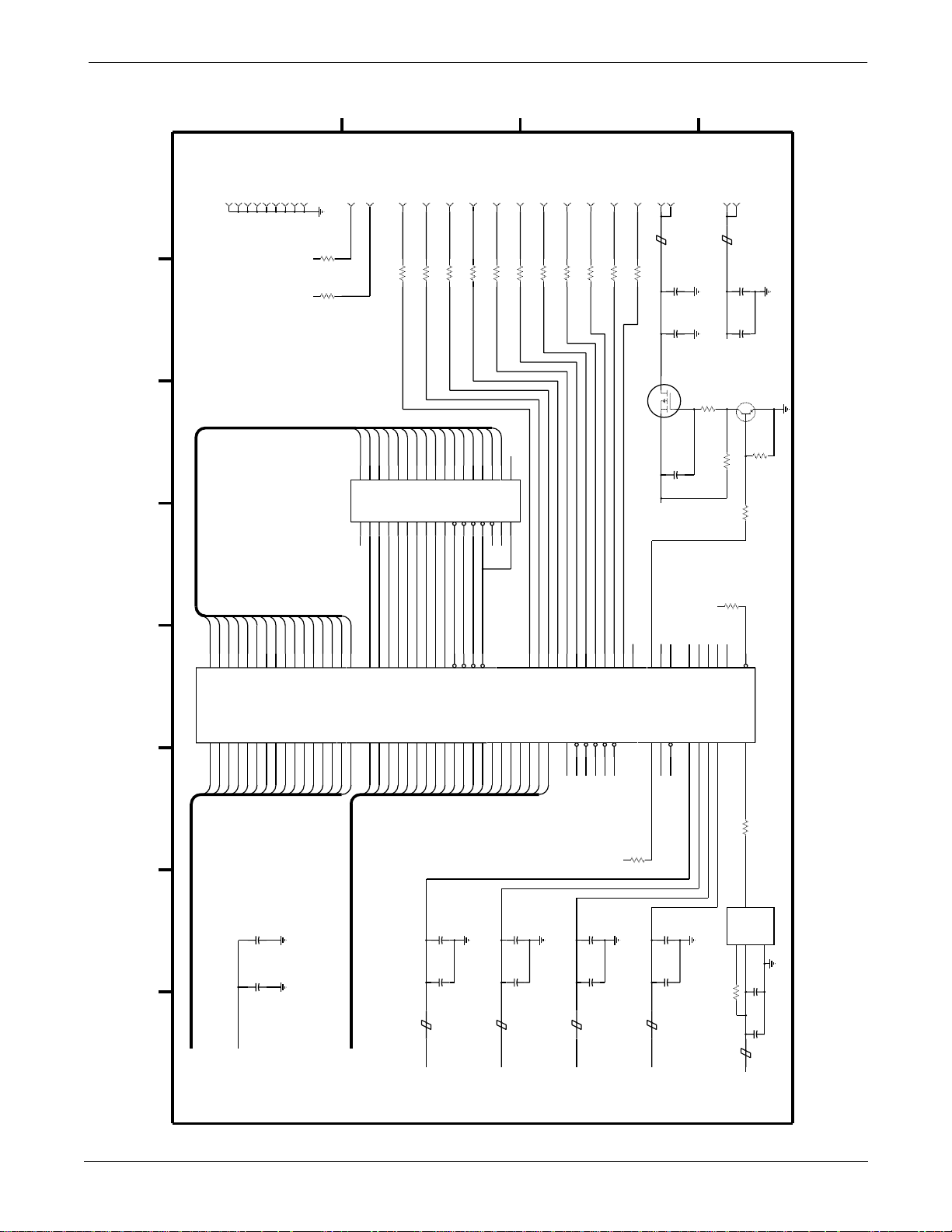
Page 6 of 18
UPPER LEVEL OVERVIEW: Schematic Diagram PN SD800772-002A
D
C
B
A
F65510
U25
J3-6
CONNECTOR
J3 - DISPLAY
MD13
MD14
MD15
82
80
MD1481MD15
5
D23
D21
D22
J3-10
MD12
MD1283MD13
D128D137D146D15
D20
J3-12
MD10
MD11
85
84
MD11
9
D18
D19
J3-14
J3-16
MD9
86
MD10
D1010D11
D17
MD8
D16
J3-8
J3-19
J3-21
J3-23
R138
MD7
MA1
A12
LD2
49.9
MD6
D6D7D8
MA0
MA078MA177MA276MA375MA474MA573MA672MA771MA8
A11
MD5
D5
RAS
666769
RAS
A1033A1134A1235A1336A1437A1539A1640A1741A1842A19
49.9
R137
MD4
[WEH] WE
LD3
MD3
68
J3-25
MD2
[CAS] CASH
49.9
R136
MD1
LCAS
[WEL] CASL
UD0
OE
GND
J3-20
J3-22
J3-24
J3-26
J3-5
LD0
D13
R140
MD12
D12
MA6
A17
49.9
MD11
D11
MA5
A16
R139
MD9
MD10
D10
MA4
MA3
A14
A15
LD1
49.9
MD8
D9
MA2
A13
MD7
D31
MD6
D30
+
+
MD5
D29
5
5
MD4
D28
BLANK
8-BIT
R125
10K
R124
10K
MD13
MD14
MD15
987643210
33333333198754323
D14
D15
NC
A8A7A6A5A4A3A2A1A0WEUCAS
TC514260
U26
56543298764389712
12222211111122211
GND
MA8
MA7
MD0
MD1
MD2
MD3
96
70
MD0
MD195MD294MD393MD492MD591MD690MD789MD887MD9
D0
21D120D219D318D417D516D615D714D812D911
43
D24
D25
D26
D27
A19
A18
J3-15
MD0
R135
0
D0D1D2D3D4
NC
NC41
J3-7
UD1
49.9
NC42
NC
NC
62
49.9
R134
J3-17
UD2
23A124A225A326A427A528A629A730A831A932
A0A1A2A3A4A5A6A7A8A9A10
A0
49.9
R133
UD3
46
J3-18
AEN
GND
R141
BHE
44
CP2
49.9
IORD
1
J3-13
P055P156P257P358P459P560P661P7
IOWR
2
CP1
49.9
R131
64
SHFCLK
MEMR
47
48
J3-11
53LP52DE65
MEMW
J3-2
J3-1
J3-9
S
BLM41P03
FB16
C1411025V
49.9
R132
+
C140
SD
32
C128
+12
NC63
NC64
NC65
51
50
49
FLM
ACTIND
ENAVEE
ENAVDD
RESET99RFSH
RDY
3
45
+5
20%+C1391025V
50V
.1
Q12
IRFR9010
G
1
50V,20%
.1
GND
422547997
VSS1
VDD1
133863
20%
GND
VSS2
VDD2
BLM41P03
FB15
R126
10K
10K
R127
+
5
GND
GND
VSS3
VSS4
VDD3
VDD4
88
J3-3
+5
3
R105
R110
GND
VSS5
J3-4
C144
.1
Q11
1
10K
10K
98
STNDBY
CLKIN
100
20%
3904
R106
2
10K
Revision A
C120
4.7
20V
20%
+
C132
4.7
20V
20%
+
8 76543 21
D31-D0
+5
50V
5%
C118
.01
C119
.1
BLM11A20
FB10
A27-A0
+5
Eagle 3000 Patient Monitor
415397-038
BLM11A20
FB11
+5
C117
.01
C126
.1
50V
VIDEO_BHE*
VIDEO_IORD*
VIDEO_IOWR*
5%
BLM11A20
FB14
+5
C137
.01
C138
.1
VIDEO_RDY
VIDEO_MEMRD*
VIDEO_MEMWR*
R100
10K
+
5
50V
5%
BLM11A20
FB12
VIDEO_RESET
50V
5%
C129
.01
C127
.1
+5
10
R104
3
EN
45.000MHz
Y4
1
4
10K
R118
BLM11A20
FB13
OUT
VCC
+5
2
C130
.01
C131
.1
GND
OSCILLATOR
50V
5%
2-29
Page 49
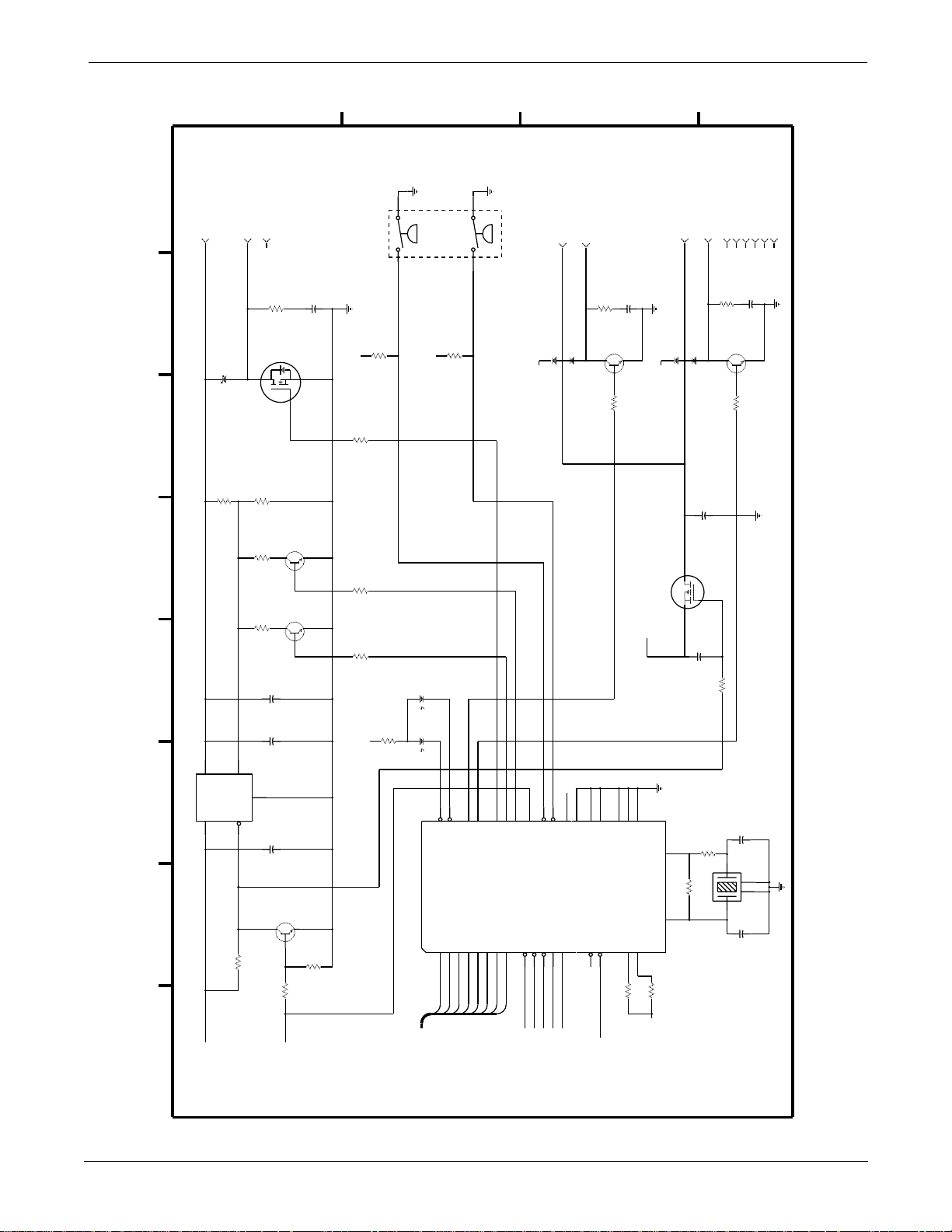
Page 7 of 18
UPPER LEVEL OVERVIEW: Schematic Diagram PN SD800772-002A
D
C
B
A
J5-1
CONNECTOR
J5 - NBP COMPRESSOR
+V_PUMP
CR22
R70
J5-2
PUMP_DRV
MBRS140T3
2
10K
R83
R82
R81
J5-3
NC44
R55
Q5
D
2.74K
6.34K
3.01K
1/8W
1%
10
SMD25N05
3
S
G
1
Q6
3904
3
1
Q7
3904
3
1
C49
2
2
VALVE1
-4J11
CONNECTOR
J11 - NBP VALVE
3
2
NC45
+12V_VALVE
SOLENOID
0.06" DIAMETER
-1J11
VAL1_DRV
MMBD7000
1
CR17
R11
R10
3
49.9
Q1
1
1K
C12
3904
50V
20%
.1
2
+12
1
S2
2
50V
20%
.1
R87
1K
+
5
R68
1K
R78
10K
R77
10K
DUAL
300mmHg
PRESSURE
+
5
SENSOR
R88
1K
4
150mmHg
3
VALVE0
SOLENOID
0.03" DIAMETER
-10J11
-7J11
VAL0_DRV
R13
MMBD7000
3
3
1
2
NC46
CR18
R12
+12V_VALVE
C7
4.7
20V
20%
+
Q3
IRFR9010
G
SD
1
32
5%50V,
C27
.1
-2J11
NC47
49.9
Q2
1
1K
-3J11
NC48
3904
-5J11
NC49
C13
2
-6J11
NC50
50V
.1
-8J11
NC51
20%
-9J11
NC52
C742225V
+
C732225V
+
1
54
ADJ
OUT
U21
LM2941CT
IN
8 76543 21
+12
R69
2
10K
3
GND
EN
C81
.1
3
R66
10%
10%
50V
20%
Q4
3904
2
1
10K
NBP_ENABLE
R67
10K
DS8
GREEN
DS7
RED
R54
1K
+
5
+5
24
40
27
26
PUMP_DRV
VOLT_SEL0
VOLT_SEL1
RD
I/O_1
I/O_0
20
D24
OE*
29
OE
OVP_300mmHg
OVP_150mmHg
WRCSA1
5
4
19
18
A1
WE0*
NBP_CS*
16
VPP
A0
A0
34
MODE
39
38
44
NBP_ID1
NBP_ID0
RESET_IN
RESET_OUT
31
30
NC43
R801KR79
RESETH*
33
6
NOT USED
NOT USED
NOT USED
FLOAT
TESTMODE
37
36
1K
NBP_NORMAL_MODE*
OSC_OUT
OSC_IN
U20
NBP INTERFACE ASIC
23
22
LED_RED
PLCC 44
I/O_7
1715131211
D31
D30
D31-D0
42
41
LED_GRN
VALVE1_DRV
I/O_6
I/O_5
I/O_4
D29
D28
D27
28
VALVE0_DRV
I/O_3
I/O_2
987
D26
D25
2
1
R61
1M
10K
R26
C72
R62
2K
Y2
14
4.194304MHz
C71
50V
5%
22pF
23
50V
5%
22pF
2-30
Eagle 3000 Patient Monitor
415397-038
Revision A
Page 50
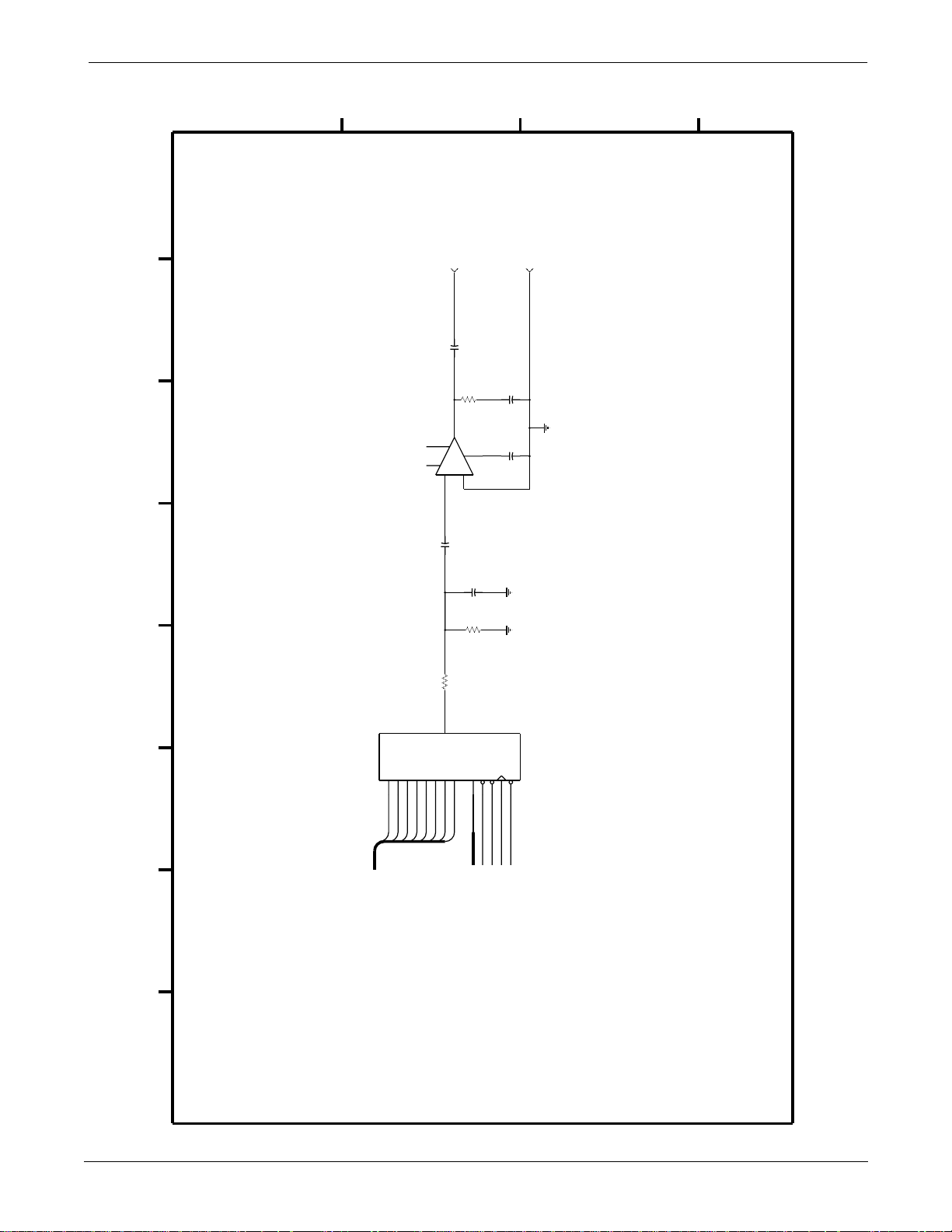
Page 8 of 18
UPPER LEVEL OVERVIEW: Schematic Diagram PN SD800772-002A
D
C
B
A
NC6
NC6
CONNECTOR
J4 - SPEAKER
SPEAKER +
C5
U2
8
7
1
6
+
3
C11
549
R41
J4-1
+
470
5
-
LM386N
2
50V
.047
SPEAKER
20%
25V
R23
10
1/8W
7
5%
50V
C31
.22
R35
453
1%
(8 OHM)
5%
C21
.047
C221025V
+
J4-2
SPEAKER -
5%50V,
20%
8 76543 21
5
SO
765432100EECE
DDDDDDDDACW
YMZ284
U13
9012345632178
1111111
D31
D30
D29
D28
D27
D26
D25
D24
D31-D0
A0
A27-A0
AUDIO_CS*
K
ET
L
S
R
AUDIO_WR*
AUDIO_CLK
AUDIO_RESET*
Revision A
Eagle 3000 Patient Monitor
415397-038
2-31
Page 51
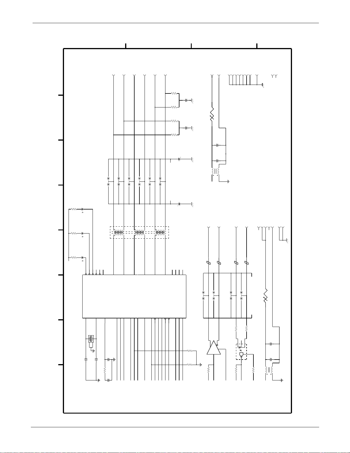
UPPER LEVEL
VERVIEW
UPPER LEVEL OVERVIEW: Schematic Diagram PN SD800772-002A
hematic DiagramPN SD800772-002A
Page 9 of 18
D
CONNECTOR
J9 - ETHERNET
J9-7
NC23
A
J9-15
NC29
E2
J9-13
SMPTC
1 2
B
J9-6
.75A
C101025V
+
C17
.1
20%
50V
20%
-1MH7
J9-8
J9-11
J9-14
J9-16
J9-1
J9-4
J9-17
METAL SHELL OF
15-PIN CONNECTOR
C
J9-5
J9-12
J9-3
J9-10
J9-2
J9-9
1/8W
1%
R19
39.2
5%
C15
.01
R20
39.2
1/8W
1%
R22
39.2
1/8W
1%
50V 50V
5%
C16
.01
R21
39.2
1%
1/8W
SMBJ13A
CR5
R3
1K
R2
1K
R1
1K
+5
U4
DS3
RED
DS2
AMBER
DS1
GREEN
NC53
NC54
40414243444524
TPUL*
TPPLR*
TX_LED*
RX_LED*
CLSN_LED*
X2
X1
68160
16
17
20MHz
Y1
1
4
2
3
,50V,5%
C19
C20
68pF
68pF
MMBD7000CR10
3
21
6
1
T1
PE-65728
1
NC55
TPJABB
AUI_RX+
MFILT
2
12
50V,5%
C25
3900pF
MMBD7000CR11
MMBD7000CR8
3
3
21
21
5
3
1
1
2
4
23
26
AUI_RX-
RX
RENA
RCLKTXTENA
1
505249
MMBD7000CR7
MMBD7000CR9
3
3
21
21
2
0
1
1
5
7
22
AUI_TX+25AUI_TX-
TCLK
CLSN
LOOP
6
51
48
MMBD7000CR6
3
21
9
8
21
AUI_CLSN+
AUI_CLSN-
TPEN*
APORT
TPAPCE
TPSQEL*
TPFULDL*
9
294627
28
CLAMP+ CLAMP-
CR16
SMBJ13A
REGION
ISOLATED
OPT_TP_RX+
OPT_TP_RX-
OPT_TP_TX+
OPT_TP_TX-
323137
36
TP_TX-
TP_TX+
TP_RX-
TP_RX+
CS0
CS1
CS2
345
R32
R34
10K
10K
L4
-9J10
CONNECTOR
J10 - RS-422
ASYNC_TX+
BLM11A20
FB3
MMBD7000CR3
3
21
6
U3
ADM485
PLM250S40
+12
-5J10
ASYNC_TX-
BLM11A20
FB4
MMBD7000CR4
3
21
7
4
3
-3J10
ASYNC_RX-
ASYNC_RX+
BLM11A20
BLM11A20
FB2
FB1
MMBD7000CR1
MMBD7000CR2
3
3
21
21
49.9R949.9
R8
1/8W,1%
NC0
4
3
2
HCPL2602
U1
6
-1J10
CLAMP-
CLAMP+
1/8W
7
-8J10
-7J10
-6J10
-4J10
-2J10
NC56
E1
SMPTC
1%
1 2
NC57
.75A
C91025V
+
C14
.1
20%
50V
-10J10
5%
-11J10
METAL SHELL OF
9-PIN CONNECTOR
2-32
R25
50V,5%,
8 76543 21
287
C26
50V
0.039
5%
ETH_RXD
ETH_RX_EN
ETH_RXD_CLK
+5
+5
+5
GND
GND
GND
ETH_TXD
ETH_CLSN
ETH_TX_EN
ETH_LOOP
ETH_TXD_CLK
Eagle 3000 Patient Monitor
415397-038
L2
10K
R24
+5
GND
+5
RS422_TXD
1K
R7
+5
+5
RS422_RXD
R18
10K
+5
PLM250S40
+12
Revision A
Page 52
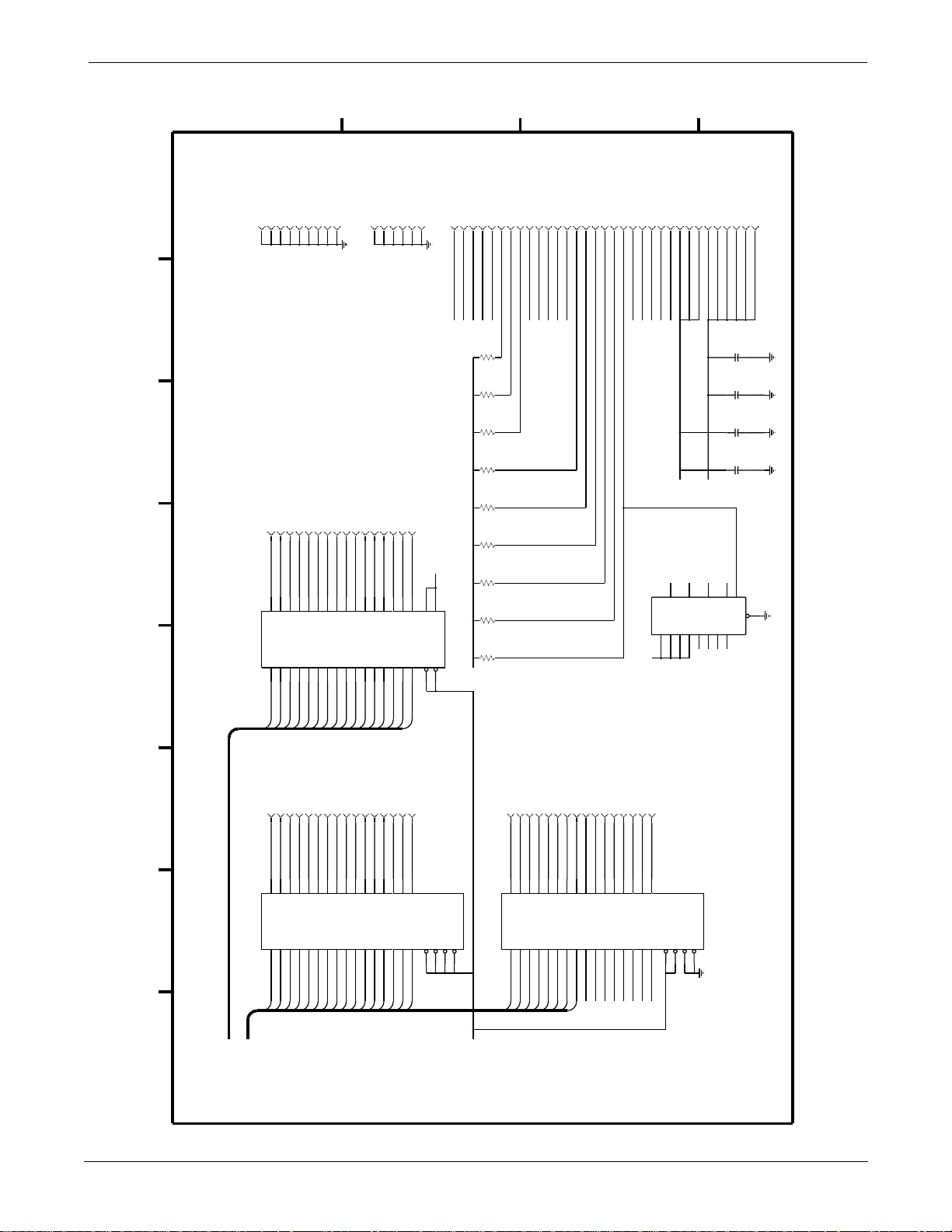
age 10 of 18
UPPER LEVEL OVERVIEW: Schematic Diagram PN SD800772-002A
J6-A30
J6-B29
J6-B30
J6-C29
C
J6-C30
J6-B6
J6-C5
J6-C6
J6-A9
DK1*
RESETH*
OPT_BRD_CS*
FLASH_WE1*
R45
R39
R51
R46
R43
J6-A10
J6-C4
J6-A4
J6-A6
J6-A8
DK0*
STARS_TXD
STARS_RXD
AVEC*/IACK5*
OPT_BRD_IRQ2*
OPT_BRD_IRQ5*
10K
10K
10K
10K
10K
J6-B8
J6-C8
STARS_SERVICE*
D
J6-A11
J6-A13
J6-A15
J6-A17
J6-A19
J6-A21
J6-A23
J6-A25
J6-A27
J6-A29
J6-A7
J6-B7
J6-C7
J6-A2
ETCO2_TXD
ETCO2_RXD
ETCO2_IRQ3*
SPARE1_I/O
B
J6-A3
J6-A5
J6-B4
J6-B5
J6-C3
J6-C2
SPARE2_I/O
OPT_BRD_AVAIL*
MARK_IN_IRQ4*
BOOT_SEL*
OPT_TP_TX+
OPT_TP_TX-
J6-A1
J6-B3
J6-B2
J6-A28
NC60
OPT_TP_RX+
OPT_TP_RX-
+5
J6-B1
J6-C1
J6-A31
+12
J6-A32
J6-B31
J6-B32
C321025V
+
C33
.1
C341025V
+
C37
.1
J6-C31
50V
A
J6-C32
20%
20%
20%
J6-B28
J6-C28
J6-B27
J6-C27
J6-B26
J6-C26
J6-B25
J6-C25
J6-C24
J6-B24
OPT_D31
OPT_D30
OPT_D29
OPT_D28
OPT_D27
OPT_D26
OPT_D25
OPT_D24
OPT_D23
OPT_D22
474644434140383736353332302927
1A1
1A2
1A3
1A4
1A5
1A6
1A7
1A8
2A1
2A2
1B1
1B2
1B3
1B4
1B5
1B6
1B7
1B8
2B1
U7
74ACTQ16245
23568
D31
D30
J6-C9
J6-B9
OPT_A0
OPT_A1
235
1Y1
1Y2
1A1
1A2
U9
74ACTQ16244
474644
D29
D28
D27
J6-C10
J6-B10
OPT_A2
OPT_A3
OPT_A4
6
8911
1Y3
1Y4
1A3
1A4
43
414038
2B2
9
111213141617202223
D26
D25
D24
D22
D23
J6-C11
J6-B11
J6-C12
J6-B12
J6-C13
J6-B13
OPT_A5
OPT_A6
OPT_A7
OPT_A8
OPT_A9
12
131416
2Y1
2Y2
2Y3
2Y4
3Y1
3Y2
2A1
2A2
2A3
2A4
3A1
3A2
37
363533
J6-B22
J6-C23
J6-B23
OPT_D21
OPT_D20
OPT_D19
2A3
2A4
2A5
2B3
2B4
2B5
19
D19
D20
D21
J6-C14
J6-B14
J6-C15
OPT_A10
OPT_A11
OPT_A12
17
192022
3Y3
3Y4
4Y1
3A3
3A4
4A1
32
302927
J6-C21
J6-B21
J6-C22
OPT_D16
OPT_D18
OPT_D17
26
2A6
2A7
2A8
2B6
2B7
2B8
D16
D17
D18
J6-B15
J6-C16
J6-B16
OPT_A13
OPT_A14
OPT_A15
23
4Y2
4Y3
4Y4
4A2
4A3
4A4
26
1
1G
48
1G
1
R/W*
24
2DIR
1DIR
2G
25
2G
48
R44
10K
R42
10K
R59
10K
R123
10K
+5
J6-B17
J6-C18
J6-B18
OPT_A17
OPT_A18
OPT_A19
6
1Y2
1Y3
1Y4
1A2
1A3
1A4
43
J6-B19
J6-C19
J6-C20
OPT_A20
OPT_A21
OPT_A22
8911
2Y1
2Y2
2Y3
2A1
2A2
2A3
414038
J6-B20
J6-A12
OPT_A23
OPT_SIZ1
OPT_SIZ0
12
131416
2Y4
3Y1
2A4
3A1
37
363533
J6-C17
OPT_A16
235
1Y1
3G
4G
24
25
1A1
U8
74ACTQ16244
474644
J6-A14
J6-A16
OPT_DS*
OPT_AS*
17
3Y2
3Y3
3Y4
3A2
3A3
3A4
32
J6-A22
J6-A20
J6-A18
OPT_OE*
OPT_R/W*
192022
4Y1
4Y2
4A1
4A2
302927
U10
74ACT157
3401653
111
+
5
J6-A26
J6-A24
OPT_WE0*
OPT_WE1*
23
4Y3
4Y4
4A3
4A4
26
MAIN_BRD_CS*
NC58
NC59
2
1
9
7
Y
Y
YYS
4
3
2
BABABAB
4433221
1
BOOT_CS0*
OPT_BRD_CS7*
1G
2G
3G
4G
1
24
25
48
OPT_BRD_CS*
4
1
1
1
5
G
A
1
2
BOOT_CS0*
OPT_BRD_CS7*
Revision A
A0A1A2A3A4A5A6A7A8A9A10
8 76543 21
D31-D0
A27-A0
A11
A12
A13
A14
A15
OPTION_BUS_EN*
Eagle 3000 Patient Monitor
415397-038
A16
A17
A18
A19
A20
A21
A22
A23
SIZ1
SIZ0
AS*
DS*
OE*
R/W*
WE1*
WE0*
2-33
Page 53
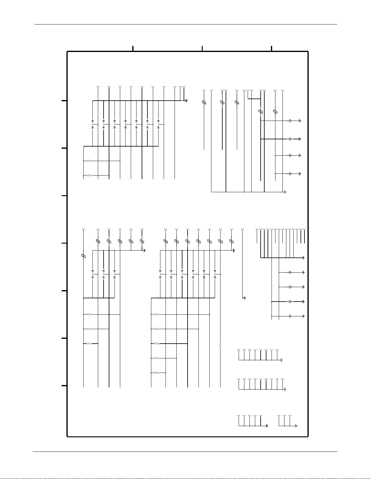
Page 11 of 18
UPPER LEVEL OVERVIEW: Schematic Diagram PN SD800772-002A
CONNECTOR
DEBUG MODE
J12 - BACKGROUND
R29
10K
R27
10K
+5
D
-10J12
MMBD7000CR12
MMBD7000CR19
3
3
21
21
IPIPE0/DSO
-8J12
-4J12
MMBD7000CR14
3
21
21
IFETCH/DSI
BKPT/DSCLK
-6J12
-2J12
MMBD7000CR20
MMBD7000CR21
3
3
21
21
BERR*
FREEZE/CONFG2
-1J12
MMBD7000CR15
MMBD7000CR13
3
21
DS*
C
-7J12
3
RESETH*
-9J12
+5
-3J12
-5J12
J8 - DAS
CONNECTOR
BLM11A20
FB5
J8-2
J8-1
DAS_TXD
J8-3
BLM11A20
FB6
DAS_RXD
J8-4
FB7
B
J8-5
BLM11A20
DAS_RESET*
A
J8-7
J8-8
J8-6
J8-9+12
J8-10
J8-12
J8-11+5
BLM41P03
BLM41P03
FB8
FB9
C891025V
20%
+
5%
50V
C105
.01
C901025V
20%
+
C106
.1
-6J25
-5J25
CONNECTOR
J25 - TRIM KNOB
BLM11A20
FB22
+5
BLM11A20
FB21
MMBD7000CR26
3
21
R119
10K
R120
10K
R121
10K
TRIM_0
BLM11A20
FB20
MMBD7000CR25
3
21
8 76543 21
-4J25
-3J25
BLM11A20
FB19
MMBD7000CR24
3
21
TRIM_1
TRIM_PUSH*
-2J25
BLM11A20
FB18
-1J25
BLM11A20
FB17
CONNECTOR
J7 - USER INTERFACE
BLM11A20
FB29
MMBD7000CR32
21
R129
10K
R128
10K
R115
10K
R116
10K
R117
10K
+5
J7-8
J7-7
BLM11A20
BLM11A20
FB28
FB27
MMBD7000CR31
MMBD7000CR30
3
3
GRAPH_GO/STOP*
3
21
21
SILENCE_ALARM*
J7-6
J7-5
BLM11A20
BLM11A20
FB26
FB25
MMBD7000CR29
MMBD7000CR28
3
21
21
BP_ZERO_ALL*
NBP_GO/STOP*
J7-4
J7-3
J7-2
BLM11A20
BLM11A20
FB24
FB23
MMBD7000CR27
3
3
21
1K
R130
VIDEO SHEILDMOUNTING HOLES
+5
DISPLAY_ON/OFF*
-10BK1
-1BK1
-1MH1
J7-1
-11BK1
-2BK1
-1MH2
J2-1
CONNECTOR
J2 - POWER
NC61
-12BK1
-13BK1
-3BK1
-4BK1
-1MH3
-1MH4
J2-5
-14BK1
-5BK1
-1MH6
J2-4
J2-7
J2-8
J2-11
J2-6
J2-2
J2-3
+12
NC62
+5
+12
-15BK1
-16BK1
-6BK1
-7BK1
-9BK1
-8BK1 -17BK1
-1BK2
-2BK2
J2-12
J2-13
C31025V
+
C4
C21025V
+
C1
-3BK2
J2-14
J2-9
J2-10
+5
+12
+12
20%
.1
20%
20%
50V
.1
2-34
Eagle 3000 Patient Monitor
415397-038
CRYSTAL SHIELD
Revision A
Page 54
Page 12 of 18
UPPER LEVEL OVERVIEW: Schematic Diagram PN SD800772-002A
D
C
B
A
POWER SUPPLY BYPASS
REFD
POWER SUPPLY BYPASS
REFD VALUE PWR RTN
VALUE PWR RTN
POWER SUPPLY BYPASS
C65 .1 +5 GND
REFD VALUE PWR RTN
POWER SUPPLY BYPASS
C85 .1 +5 GND
REFD
C84 .1 +5 GND
C103 .1 +5 GND
C82 .1 +5 GND
C101 .1 +5 GND
C79 .1 +5 GND
C102 .1 +5 GND
C45 .1 +5 GND
C104 .1 +5 GND
C80 .1 +5 GND
C46 .1 +5 GND
C67 .1 +5 GND
C38 .1 +5 GND
C68 .1 +5 GND
C39 .1 +5 GND
C69 .1 +5 GND
C40 .1 +5 GND
C83 .1 +5 GND
C41 .1 +5 GND
C66 .1 +5 GND
C100 .1 +5 GND
C142 .1 +5 GND
C107 .1 +5 GND
C125 .1 +5 GND
C136 .1 +5 GND
C115 .1 +5 GND
C108 .1 +5 GND
C143 .1 +5 GND
C116 .1 +5 GND
C113 .01 +5 GND C114 .1 +5 GND
C50 .1 +VBAT GND
C94 .1 +5 GND
C92 .1 +5 GND
C93 .1 +5 GND
C91 .1 +5 GND
C78 .1 +5 GND
C60 .1 +5 GND
C76 .1 +5 GND
C58 .1 +5 GND
C77 .1 +5 GND
C59 .1 +5 GND
C75 .1 +5 GND
C57 .1 +5 GND
C133 .1 +5 GND
C121 .1 +5 GND
C122 .1 +5 GND
C123 .01 +5 GND C124 .01 +5 GND C134 .01 +5 GND
C36 .1 +5 GND
C44 .01 +5 GND
C43 .1 +5 GND
C55 .1 +5 GND
C56 .1 +5 GND
C53 .1 +5 GND
C54 .1 +5 GND
C52 .1 +5 GND
C51 .1 +5 GND
C97 .1 +5 GND
C95 .1 +5 GND*
C63 .1 +5 GND
C61 .1 +5 GND
**
C135 .1 +VBAT GND
C42 .1 +VBAT GND
C64 .1 +5 GND
C62 .1 +5 GND
C145 .1 +5 GND
C47 .1 +5 GND
C86 .1 +5 GND
C48 .1 +5 GND
C70 .1 +5 GND
C35 .1 +5 GND
C24 .1 +5 GND
C23 .1 +5 GND
GND
C18 .1 +5 GND
C30 .1 +5 GND
C29 .1 +5 GND
C28 .1 +5 GND
C8 .1 +5 GND
C6 .1 +12 GND
C146 .1 +5 GND
C147 .1 +5 GND
Revision A
7,17,26,36,
41,47,57,63,
POWER RETURN VALUE PWR RTN
IC POWER/RETURN CHART
IC
8 76543 21
160,166,175,
147,153,156,
128,133,141,
111,118,123,
94,102,106,
70,76,83,88,
+5 GND
12,31,42,52,
67,80,89,98,
107,115,121,
U12 68EN360Q
223,232,238
47,59,72,82
206,211,217,
195,197,200,
181,186,190,
7,19,32,42,
+5 GND
3,13,26,38,
43,53,66,78
216,220,235
163,176,184,
193,201,208,
137,150,157,
U24 7128E
Eagle 3000 Patient Monitor
28,34,39,45
28,34,39,45
28,34,39,45
4,10,15,21,
4,10,15,21,
4,10,15,21,
+5 GND
7,18,31,42
U6 +VBAT64613 GND24,23,22 1,12
U22 +VBAT74AC00 14 7 GND
U5 +VBAT628128L GND32 16
U19 +528F016 GND9,37,43 21,42,48
U11 +5X24C16 GND84
U18 +528F016 GND9,37,43 21,42,48
U17 +5TC514260 GND1,6,20 21,35,40
U15 +5TC514260 GND1,6,20 21,35,40
U16 +5TC514260 GND1,6,20 21,35,40
U14 +5TC514260 GND1,6,20 21,35,40
U26 +5TC514260 GND1,6,20 21,35,40
U13 +5YMZ284 GND46
U10 +574ACT157 GND16 8
U23 +5MAX802L GND23
U9 74ACTQ16244
8,13,14,19,47,
+5 GND
7,18,31,42
7,18,31,42
7,10,11,15,
74ACTQ16245 +5 GND
U8 74ACTQ16244
U7
U20 +5407827 GND3,14,25,35 10,21,32,43
20,33,34,39
+5
U4 68160 18,30,35,38
U3 +5ADM485 GND85
U2 +12LM386 GND64
U1 +5HCPL2602 GND85
415397-038
C44, C113, C123, C124, C134,
C6
U27 +5TCU04 GND35
U28 +5TC126 GND84
NOTES:
1.) THE FOLLOWING CAPS ARE 50V, 5%:
2.) THE FOLLOWING CAPS ARE 50V, 20%:
3.) * INDICATES CAPACITORS NOT INSTALLED
2-35
Page 55
Page 13 of 18
UPPER LEVEL OVERVIEW: Schematic Diagram PN SD800772-002A
5-D2,D6
5-D2,D6
D3: 1-D5
B
5-C2,C6
D4: 1-D5
5-C2,C6
D5: 1-D5
5-C2,C6
D6: 1-D5
BOOT_SEL*: 2-C2
10-B2
BP_ZERO_ALL*: 2-B2
11-C8
CAP_ENABLE: 2-D2
D
3-B8
CAP_READ: 1-C7
3-B4
5-B4,B8
CAS0*: 1-B1
5-B4,B8
CAS1*: 1-B1
5-C4,C8
CAS2*: 1-B1
5-C4,C8
CAS3*: 1-B1
CLAMP+: 9-B6,C4
CLAMP-: 9-B6,C3
C
CNFG0: 1-B1
2-A8
CNFG1: 1-B1
2-A8
CP1: 6-B1
CP2: 6-B1
5-D2,D6
D0: 1-D6
5-D2,D6
D1: 1-D5
D2: 1-D5
5-C2,C6
D7: 1-D5
5-C2,C6
D8: 1-D5
5-C2,C6
D9: 1-D5
5-C2,C6
D10: 1-D5
A
5-C2,C6
D11: 1-D5
A17: 1-A4
A7: 1-A5
2-D7
3-C2
3-D2
4-C4,C7
4-C4,C7
6-C6
10-C8
2-D7
4-C4,C7
A18: 1-A4
5-B3,B7,C3,C7
6-C6
10-D8
3-D2
4-C4,C7
A8: 1-A5
6-C6
10-B8
2-D7
4-B4,B7
6-C6
A19: 1-A4
5-B3,B7,C3,C7
6-C6
10-D8
3-D2
4-C4,C7
A9: 1-A5
10-B8
2-D7
4-B4,B7
10-B8
A20: 1-A4
5-B3,B7,C3,C7
6-C6
10-C8
3-D2
4-C4,C7
A10: 1-A5
10-B8
10-B8
A21: 1-A4
A22: 1-A4
A23: 1-A4
5-B3,B7,C3,C7
6-C6
10-C8
3-D2
A11: 1-A5
10-B8
A24: 1-A4
4-C4,C7
6-C6
10-C8
A25: 1-A4
A12: 1-A5
A26: 1-A4
A27: 1-A3
3-D2
4-C4,C7
6-C6
2-C7
AS*: 1-A2
10-C8
10-B8
3-C2
A13: 1-A5
8-C7
AUDIO_CLK: 2-B8
AUDIO_CS*: 2-C2
4-C4,C7
6-C6
10-C8
8-C7
A14: 1-A4
8-C7
AUDIO_RESET*: 2-D2
3-C2
4-C4,C7
6-C6
8-C7
AUDIO_WR*: 2-C2
10-C8
A15: 1-A4
10-C2
AVEC*/IACK5*: 1-C1
3-C2
4-C4,C7
BERR*: 1-A8
6-C6
2-C8
10-C8
11-C3
BKPT/DSCLK: 1-B1
3-C2
A16: 1-A4
11-D4
BOOT_CS0*: 1-C1
4-C4,C7
6-C6
10-C8
2-C8
10-A5,B5
2-36
6-B4
7-B5,D8
9-A4,A8,B4
10-A3
11-A5,B3,B6
+12: 4-C2,C5
LABEL PAGE COORDINATES LABEL PAGE COORDINATES LABEL PAGE COORDINATES LABEL PAGE COORDINATES
+VBAT: 3-B4,C4
8 76543 21
+V_PUMP: 7-D2
2-C7
A0: 1-A6
3-B2,D2
6-B6
7-B8
8-C6
10-D8
3-B2,D2
4-C4,C7
6-B6
7-B8
10-D8
3-B2,D2
4-C4,C7
5-B3,B7,D3,D7
6-B6
A1: 1-A5
A2: 1-A5
Eagle 3000 Patient Monitor
415397-038
10-D8
A3: 1-A5
3-B2,D2
4-C4,C7
5-B3,B7,D3,D7
6-C6
10-D8
3-D2
4-C4,C7
5-B3,B7,D3,D7
A4: 1-A5
6-C6
10-D8
A5: 1-A5
3-D2
4-C4,C7
5-B3,B7,D3,D7
6-C6
10-D8
A6: 1-A5
3-D2
4-C4,C7
5-B3,B7,C3,C7
6-C6
10-D8
Revision A
Page 56
Page 14 of 18
UPPER LEVEL OVERVIEW: Schematic Diagram PN SD800772-002A
D_TRIM_1: 1-B7
2-B8
D_TRIM_PUSH*: 1-B7
2-B8
D
EE_CLK: 1-C6
3-C6
EE_DATA: 1-C6
3-D6
ETCO2_IRQ3*: 1-C1
10-B2
ETCO2_RXD: 1-C7
10-B2
ETCO2_TXD: 1-C7
10-B2
ETH_CLSN: 1-B7
9-C8
ETH_LOOP: 1-C7
9-C8
ETH_RXD: 1-D1
C
9-D8
ETH_RXD_CLK: 1-D1
9-D8
ETH_RX_EN: 1-B7
9-D8
ETH_TXD: 1-D1
9-C8
9-C8
ETH_TXD_CLK: 1-C1
9-C8
ETH_TX_EN: 1-C7
FLASH_CS4*: 1-B1
4-B2
4-B2,B5
FLASH_WE1*: 2-C2
B
10-C2
4-B4,B8
FLASH_WP*: 2-D2
2-A8
FREEZE/CONFG2: 1-B1
11-D4
GRAPH_GO/STOP*: 2-B2
11-C8
11-D4
IFETCH/DSI: 1-B1
IPIPE0/DSO: 1-B1
11-D4
LD0: 6-C1
LD1: 6-C1
A
LD2: 6-C1
D30: 1-D3
D24: 1-D4
2-D7
3-C1,D1
2-D7
3-B1,D1
4-B2,B5
5-B2,B6
6-D6
4-C2,C5
5-B2,B6
6-C6
7-C8
8-C6
7-C8
8-C6
10-D5
10-D5
2-D7
D31: 1-D3
2-D7
D25: 1-D4
3-C1,D1
4-B2,B5
5-B2,B6
3-B1,D1
4-C2,C5
5-B2,B6
6-D6
6-D6
7-C8
7-C8
8-C6
8-C6
10-D5
DAS_RESET*: 2-D2
10-D5
D26: 1-D4
11-B3
DAS_RXD: 1-D1
2-D7
3-B1,D1
11-B3
DAS_TXD: 1-D1
4-C2,C5
5-B2,B6
6-D6
11-B3
DISPLAY_ON/OFF*: 2-B2
7-C8
8-C6
11-B8
10-D5
DK0*: 1-A2
2-D7
D27: 1-D3
2-C8
10-C2
3-B1,D1
4-C2,C5
2-C8
10-C2
DK1*: 1-A2
5-B2,B6
6-D6
7-C8
DRAM_RAS1*: 1-C1
8-C6
5-B8,C8
DRAM_RAS2*: 1-B1
10-D5
D28: 1-D3
5-B4,C4
DS*: 1-A2
2-D7
3-B1,D1
4-C2,C5
2-C7
10-B8
11-C3
5-B2,B6
6-D6
7-C8
D_BP_ZERO_ALL*: 1-B7
8-C6
2-B8
10-D5
D29: 1-D3
2-B8
D_DSPL_ON/OFF*: 1-B7
2-D7
2-B8
D_GRAPH_GO/STOP*: 1-B7
3-B1,D1
4-C2,C5
5-B2,B6
D_NBP_GO/STOP*: 1-B7
6-D6
2-B8
7-C8
8-C6
2-B8
D_SILENCE_ALARM*: 1-B7
10-D5
2-B8
D_TRIM_0: 1-B7
Revision A
5-C2,C6
5-C2,C6
5-C2,C6
D12: 1-D5
D13: 1-D5
D14: 1-D4
D15: 1-D4
LABEL PAGE COORDINATES LABEL PAGE COORDINATES LABEL PAGE COORDINATES LABEL PAGE COORDINATES
8 76543 21
5-C2,C6
4-C2,C5
D16: 1-D4
5-B2,B6
6-D6
10-C5
4-C2,C5
5-B2,B6
6-D6
10-C5
4-C2,C5
5-B2,B6
6-D6
10-C5
4-C2,C5
D17: 1-D4
D18: 1-D4
D19: 1-D4
Eagle 3000 Patient Monitor
415397-038
5-B2,B6
6-D6
10-C5
4-C2,C5
D20: 1-D4
5-B2,B6
6-D6
10-C5
4-C2,C5
D21: 1-D4
5-B2,B6
6-D6
10-C5
4-C2,C5
D22: 1-D4
5-B2,B6
6-D6
10-C5
4-C2,C5
D23: 1-D4
5-B2,B6
6-D6
10-D5
2-37
Page 57
UPPER LEVEL
VERVIEW
UPPER LEVEL OVERVIEW: Schematic Diagram PN SD800772-002A
hematic DiagramPN SD800772-002A
Page 15 of 18
OPT_A10: 10-C6
OPT_A11: 10-C6
OPT_A12: 10-C6
D
OPT_A13: 10-C6
OPT_A14: 10-C6
OPT_A15: 10-C6
OPT_A16: 10-C6
OPT_A17: 10-C6
OPT_A18: 10-B6
OPT_A19: 10-B6
OPT_A20: 10-B6
OPT_A21: 10-B6
OPT_A22: 10-B6
OPT_A23: 10-B6
OPT_AS*: 10-B6
OPT_BRD_AVAIL*: 1-C1
C
10-B2
OPT_BRD_CS*: 2-C8
10-A4,C2
10-A5
OPT_BRD_CS7*: 1-B1
OPT_BRD_IRQ2*: 1-C1
10-C2
10-C2
OPT_BRD_IRQ5*: 1-C1
OPT_D16: 10-C4
OPT_D17: 10-C4
OPT_D18: 10-C4
OPT_D19: 10-C4
B
OPT_D20: 10-C4
OPT_D21: 10-C4
OPT_D22: 10-C4
OPT_D23: 10-D4
OPT_D24: 10-D4
OPT_D25: 10-D4
OPT_D26: 10-D4
OPT_D27: 10-D4
OPT_D28: 10-D4
OPT_D29: 10-D4
OPT_D30: 10-D4
OPT_D31: 10-D4
A
OPT_DS*: 10-B6
NC44: 7-D2
1-D6
NC2:
NC45: 7-B3
1-D6
NC3:
NC46: 7-B3
1-C6
NC4:
NC47: 7-A2
1-B6
NC5:
NC48: 7-A2
1-A3
NC6:
NC49: 7-A2
1-A3
NC7:
NC50: 7-A2
1-A3
NC8:
NC51: 7-A2
1-A3
NC9:
NC52: 7-A2
1-A1
NC10:
NC53: 9-D5
NC54: 9-D5
1-B1
1-D3
NC11:
NC12:
NC55: 9-D5
NC56: 9-A5
1-D3
1-D2
NC13:
NC14:
NC57: 9-A5
NC58: 10-B4
1-D2
1-D2
NC15:
NC16:
NC59: 10-B4
NC60: 10-B2
2-C2
3-B7
NC17:
NC18:
NC61: 11-B5
3-C2
NC19:
NC62: 11-A5
3-B2
NC20:
NC63: 6-B5
NC64: 6-B5
4-C7
4-B7
NC21:
NC22:
NC65: 6-B5
NC66: 8-C3
9-A1
NC23:
NC24: 4-B7
NC67: 8-C3
NC25: 4-B7
OE*: 1-A2
NC26: 4-B7
2-B7
NC27: 4-C3
3-B4,C4
4-B5
5-B4,B8,C4,C8
7-B8
10-B8
9-A1NC29:
NC30: 4-B4
NC28: 4-B4
OPTION_BUS_EN*: 2-C2
NC31: 4-B4
10-C8
OPT_A0: 10-D6
NC32: 4-B4
NC33: 5-C7
OPT_A1: 10-D6
OPT_A2: 10-D6
NC34: 5-C7
NC35: 5-B7
OPT_A3: 10-D6
NC36: 5-B7
OPT_A4: 10-D6
NC37: 5-C3
OPT_A5: 10-D6
OPT_A6: 10-D6
NC38: 5-C3
NC39: 5-B3
OPT_A7: 10-D6
OPT_A8: 10-D6
NC40: 5-B3
NC41: 6-C4
OPT_A9: 10-C6
NC42: 6-C3
NC43: 7-B8
2-38
LD3: 6-C1
MA0: 6-C5
MA1: 6-C5
MA2: 6-C5
MA3: 6-C5
MA4: 6-C5
LABEL PAGE COORDINATES LABEL PAGE COORDINATES LABEL PAGE COORDINATES LABEL PAGE COORDINATES
8 76543 21
MA5: 6-C5
MA6: 6-C5
MA7: 6-C5
MA8: 6-C5
10-A4
10-B2
MD0: 6-C3,C5
MD1: 6-C3,D5
MD2: 6-C3,D5
MD3: 6-C3,D5
MD4: 6-C3,D5
MAIN_BRD_CS*: 4-B5
MARK_IN_IRQ4*: 1-C1
Eagle 3000 Patient Monitor
415397-038
MD5: 6-C3,D5
MD6: 6-C3,D5
MD7: 6-C3,D5
MD8: 6-C3,D5
MD9: 6-C3,D5
MD10: 6-C3,D5
MD11: 6-C3,D5
MD12: 6-C3,D5
MD13: 6-C3,D5
MD14: 6-C3,D5
2-A8
MD15: 6-C3,D5
MODCLK0: 1-B6
MODCLK1: 1-B6
2-A8
NBP_CS*: 2-C2
7-B8
NBP_ENABLE: 2-D2
7-D8
11-C8
NBP_GO/STOP*: 2-B2
NBP_NORMAL_MODE*: 2-C2
7-B8
NC0: 9-B7
NC1: 1-D6
Revision A
Page 58
age 16 of 18
UPPER LEVEL OVERVIEW: Schematic Diagram PN SD800772-002A
D
C
B
A
VIDEO_MEMRD*: 2-D2
S: 6-B1
6-B6
SILENCE_ALARM*: 2-B2
6-B6
VIDEO_MEMWR*: 2-D2
11-C8
SIZ0: 1-A3
VIDEO_RDY: 2-D2
2-C8
6-B6
VIDEO_RESET: 2-D2
10-B8
SIZ1: 1-A3
6-B6
WE0*: 1-A3
10-B8
SPARE1_I/O: 1-C1
2-C8
3-B4,C4
10-B2
SPARE2_I/O: 1-C1
7-B8
10-B2
10-B8
WE1*: 1-A3
SPARE_OUTPUT: 2-C2
2-C8
SRAM_CS3*: 1-B1
10-B8
WE2*: 1-A3
3-C4
STARS_RXD: 1-D1
2-B8
WE3*: 1-A3
10-B2
STARS_SERVICE*: 10-B2
2-B8
STARS_TXD: 1-D1
10-B2
SYSTEM_CLK: 1-B7
2-B8
TCK: 1-D8
TDI: 1-D8
TDO: 1-D8
TMS: 1-D8
TRIM_0: 2-B2
11-D8
TRIM_1: 2-B2
11-D8
TRIM_PUSH*: 2-B2
11-D8
TRIS*: 1-D8
TRST*: 1-D8
UD0: 6-C1
UD1: 6-C1
UD2: 6-B1
UD3: 6-B1
VAL0_DRV: 7-A2
VAL1_DRV: 7-B2
VIDEO_BHE*: 2-D2
6-B6
VIDEO_IORD*: 2-D2
6-B6
6-B6
VIDEO_IOWR*: 2-D2
Revision A
10-B6
OPT_OE*: 4-B2
LABEL PAGE COORDINATES LABEL PAGE COORDINATES LABEL PAGE COORDINATES LABEL PAGE COORDINATES
OPT_R/W*: 10-B6
OPT_SIZ0: 10-B6
8 76543 21
OPT_SIZ1: 10-B6
OPT_TP_RX+: 9-C5
10-B2
10-B2
OPT_TP_RX-: 9-C5
OPT_TP_TX+: 9-C5
10-B2
OPT_TP_TX-: 9-C5
10-B2
OPT_WE0*: 10-B6
OPT_WE1*: 10-B6
PB_RESET: 2-C8
3-A8
PLD_CS5*: 1-B1
2-C8
2-C8
PRTY0: 1-D3
PLD_CS6*: 1-B1
Eagle 3000 Patient Monitor
415397-038
5-C4,C8
5-C2,C5
PRTY1: 1-D3
5-B4,B8
PRTY2: 1-D3
5-B2,B5
PRTY3: 1-D3
R/W*: 1-A2
PUMP_DRV: 7-D2
2-C8
5-B4,B8,C4,C8
10-B8,C4
2-C8
RESETH*: 1-A8
3-A1
4-B4,B7
7-B8
10-C2
11-C3
RS422_RXD: 1-D1
9-B8
RS422_TXD: 1-D1
9-B8
RTC_CS*: 2-C2
3-B4
3-B1
RTC_IRQ1*: 1-C1
2-39
Page 59
Page 17 of 18
UPPER LEVEL OVERVIEW: Schematic Diagram PN SD800772-002A
D
C
B
A
2-40
12-C8
U26: 6-D4
12-B8
12-B8
12-B8
U1: 9-B7
U2: 8-C3
U3: 9-B7
U4: 9-D7
REFDES PAGE COORDINATES REFDES PAGE COORDINATES REFDES PAGE COORDINATES REFDES PAGE COORDINATES
8 76543 21
12-B8
U5: 3-D2
12-C8
U6: 3-C2
12-C8
U7: 10-D5
12-B8
12-B8
12-B8
12-B8
12-C8
12-D8
U8: 10-C7
U9: 10-D7
U10: 10-B5
U11: 3-D7
U12: 1-D6
Eagle 3000 Patient Monitor
415397-038
U13: 8-C6
12-C8
12-C8
U14: 5-C3
U15: 5-C7
12-C8
U16: 5-D3
12-C8
U17: 5-D7
12-C8
U18: 4-D3
12-C8
U19: 4-D6
12-C8
U20: 7-C7
12-B8
U21: 7-D6
12-C8
U22: 3-B3,C3
12-C8
U23: 3-B5
U24: 2-D4
12-C8
U25: 6-D6
Revision A
Page 60
Page 18 of 18
UPPER LEVEL OVERVIEW: Schematic Diagram PN SD800772-002A
B
J25-6: 11053006
J10-1: 09047055
J10-2: NC56
J10-3: 09047052
J10-4: 09039060
D
J10-5: 09047047
J10-6: 09039060
J10-7: NC57
J10-8: 09016062
J10-9: 09047044
J10-10: CGND
J10-11: CGND
J11-1: VAL1_DRV
J11-2: NC47
J11-3: NC48
J11-4: 07060056
J11-5: NC49
J11-6: NC50
J11-7: 07060056
J11-8: NC51
J11-9: NC52
J11-10: VAL0_DRV
J12-1: DS*
J12-2: BERR*
C
J12-3: GND
J12-4: BKPT/DSCLK
J12-5: GND
J12-6: FREEZE/CONFG2
J12-7: RESETH*
J12-8: IFETCH/DSI
J12-9: +5
J12-10: IPIPE0/DSO
J25-1: 11057022
J25-2: 11057019
J25-3: 11057016
J25-4: 11057013
J25-5: 11057010
A
J6-C14: OPT_A10
J6-C15: OPT_A12
J6-C16: OPT_A14
J6-A16: OPT_AS*
J6-A17: GND
J6-A18: OPT_DS*
J6-C17: OPT_A16
J6-C18: OPT_A18
J6-C19: OPT_A20
J6-A19: GND
J6-A20: OPT_OE*
J6-A21: GND
J6-C20: OPT_A22
J6-C21: OPT_D16
J6-C22: OPT_D18
J6-C23: OPT_D20
J6-A22: OPT_R/W*
J6-A23: GND
J6-A24: OPT_WE1*
J6-A25: GND
J6-C24: OPT_D22
J6-C25: OPT_D24
J6-C26: OPT_D26
J6-C27: OPT_D28
J6-A26: OPT_WE0*
J6-A27: GND
J6-A28: NC60
J6-A29: GND
J6-C28: OPT_D30
J6-C29: GND
J6-C30: GND
J6-A30: GND
J6-A31: +12
J6-A32: +12
J7-1: GND
J6-C31: +12
J6-C32: +12
J6-B1: +5
J6-B2: OPT_TP_RX-
J6-B3: OPT_TP_RX+
J6-B4: MARK_IN_IRQ4*
J7-2: 11057047
J7-3: 11057044
J7-4: 11057041
J7-5: 11057038
J6-B5: BOOT_SEL*
J6-B6: RESETH*
J6-B7: ETCO2_RXD
J7-6: 11057035
J7-7: 11057032
J7-8: 11057029
J6-B8: STARS_RXD
J6-B9: OPT_A1
J6-B10: OPT_A3
J6-B11: OPT_A5
J8-1: 11095039
J8-2: GND
J8-3: 11095044
J8-4: GND
J6-B12: OPT_A7
J6-B13: OPT_A9
J6-B14: OPT_A11
J6-B15: OPT_A13
J8-5: 11095048
J8-6: GND
J8-7: 11092055
J8-8: GND
J6-B16: OPT_A15
J6-B17: OPT_A17
J6-B18: OPT_A19
J6-B19: OPT_A21
J8-9: 11092055
J8-10: GND
J8-11: 11092059
J8-12: GND
J6-B20: OPT_A23
J6-B21: OPT_D17
J6-B22: OPT_D19
J6-B23: OPT_D21
J9-1: CGND
J9-2: 09057028
J9-3: 09057022
J6-B24: OPT_D23
J6-B25: OPT_D25
J6-B26: OPT_D27
J9-4: CGND
J9-5: 09057016
J9-6: 09074047
J6-B27: OPT_D29
J6-B28: OPT_D31
J6-B29: GND
J9-8: CGND
J9-9: 09057031
J6-B30: GND
J6-B31: +12
J9-10: 09057025
J9-11: CGND
J9-12: 09057019
J6-C1: +5
J6-C2: OPT_TP_TX-
J6-B32: +12
J9-13: 09092045
J9-14: CGND
J9-16: CGND
J9-17: CGND
J6-C3: OPT_TP_TX+
J6-C4: OPT_BRD_IRQ2*
J6-C5: OPT_BRD_CS*
J6-C6: FLASH_WE1*
J6-C7: ETCO2_IRQ3*
J6-C8: STARS_SERVICE*
J6-C9: OPT_A0
J6-C10: OPT_A2
J6-C11: OPT_A4
J6-C12: OPT_A6
J6-C13: OPT_A8
Revision A
J2-1: NC61
J2-2: +12
J2-3: +12
J2-4: GND
J2-5: GND
J2-6: GND
J2-7: +5
J2-8: NC62
8 76543 21
CONNECTOR SIGNAL CONNECTOR SIGNAL CONNECTOR SIGNAL CONNECTOR SIGNAL
J2-9: +12
J2-10: +12
J2-11: GND
J2-12: GND
J2-13: GND
J3-1: 06097054
J2-14: +5
J3-2: 06097054
J3-3: 06097061
J3-4: 06097061
J3-5: 06094020
J3-6: GND
J3-7: UD1
J3-8: 06090020
J3-9: S
J3-10: GND
J3-11: CP1
J3-12: GND
J3-13: CP2
J3-14: GND
Eagle 3000 Patient Monitor
415397-038
J3-15: UD0
J3-16: GND
J3-17: UD2
J3-18: UD3
J3-19: LD0
J3-20: GND
J3-21: LD1
J3-22: GND
J3-23: LD2
J3-24: GND
J3-25: LD3
J4-1: 08085032
J3-26: GND
J4-2: GND
J5-1: +V_PUMP
J5-2: PUMP_DRV
J5-3: NC44
J6-A1: +5
J6-A2: SPARE1_I/O
J6-A3: SPARE2_I/O
J6-A4: OPT_BRD_IRQ5*
J6-A5: OPT_BRD_AVAIL*
J6-A6: AVEC*/IACK5*
J6-A7: ETCO2_TXD
J6-A8: STARS_TXD
J6-A9: DK1*
J6-A10: DK0*
J6-A11: GND
J6-A12: OPT_SIZ1
J6-A13: GND
J6-A14: OPT_SIZ0
J6-A15: GND
2-41
Page 61

For your notes
UPPER LEVEL OVERVIEW: Schematic Diagram PN SD800772-002A
2-42
Eagle 3000 Patient Monitor
415397-038
Revision A
Page 62

3
POWER SUPPLY ASSEMBLY
AND PCB
Introduction ...........................................................................3-2
Exploded View PN 414641-001C ............................................. 3-3
Parts List PN 414641-001C ....................................................3-5
Switches and Controls PN 800706-001C ................................. 3-6
PCB Connectors PN 800706-001C .......................................... 3-7
Parts Location Diagram PN 800706-001C ............................... 3-8
Parts List PN 800706-001C ..................................................3-10
Schematic Diagram PN SD800706-001B .............................. 3-14
Revision A
Eagle 3000 Patient Monitor
415397-038
3-1
Page 63

Introduction
POWER SUPPLY ASSEMBLY AND PCB: Introduction
This chapter presents information about the power supply
assembly, pn 414641-001C, and the power supply PCB,
pn 800706-001C, used in the Eagle 3000 patient monitor.
3-2
Eagle 3000 Patient Monitor
415397-038
Revision A
Page 64
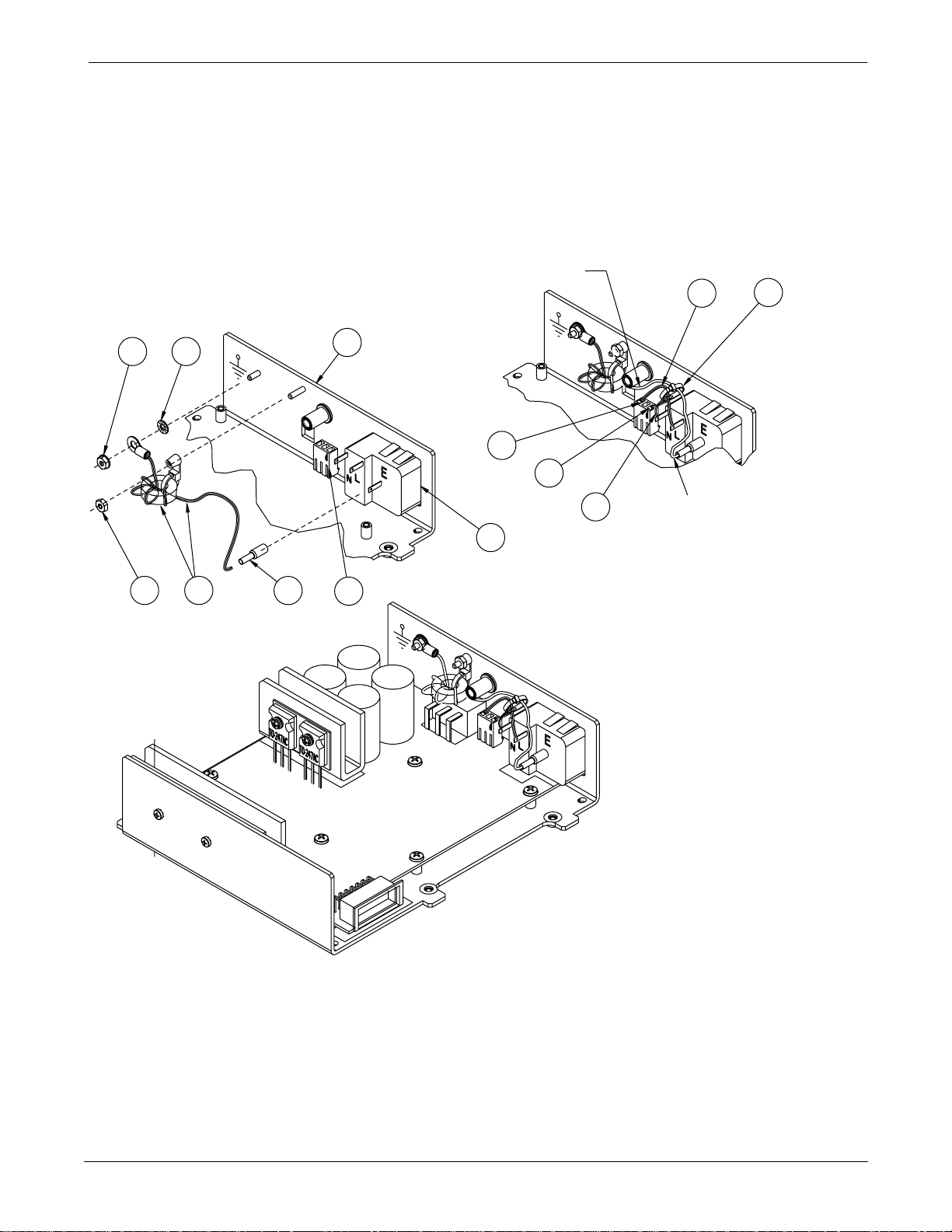
POWER SUPPLY ASSEMBLY AND PCB: Exploded View PN 414641-001C
Exploded View PN 414641-001C
Page 1 of 2
POWER INLET PARTS
10 8
94
W3
12
SEE NOTE 4
W1
14
5
2
2
13
W2
3
A1
1
J1
POWER INLET WIRING
W3
SEE NOTE 5
11
COMPLETE ASSEMBLY
NOTES:
1. FIRST, INSTALL THE 2 INDICATED SCREWS ( ITEM 7 )
FOR THE FIRST 2 THREADS ONLY.
2. SECOND, TIGHTEN NOTED HEAT SINK SCREWS ( ITEM 6 ).
3. ASSEMBLE AND TIGHTEN ALL FASTENERS.
4. ROUTE WIRES BELOW THE THREADED INSERT AS SHOWN.
5. INSTALL TIE WRAP ( ITEM 11 ) AROUND ALL 3 WIRES AND
TIGHTEN TO HOLD THEM TOGETHER SECURELY.
Revision A
Eagle 3000 Patient Monitor
415397-038
3-3
Page 65
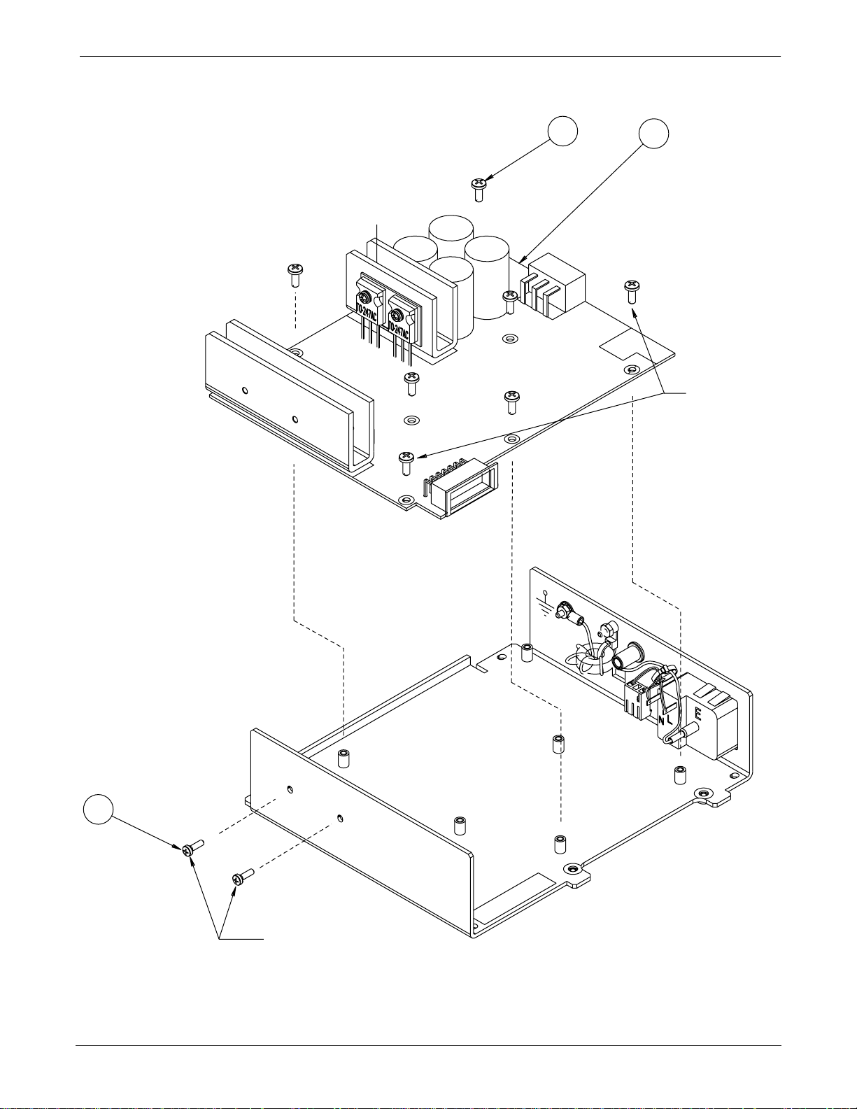
Page 2 of 2
POWER SUPPLY ASSEMBLY AND PCB: Exploded View PN 414641-001C
7
7 PLS
15
A2
SEE NOTE 1
3-4
6
2 PLS
SEE NOTE 2
PCB ASSEMBLY INSTALLATION
Eagle 3000 Patient Monitor
415397-038
Revision A
Page 66
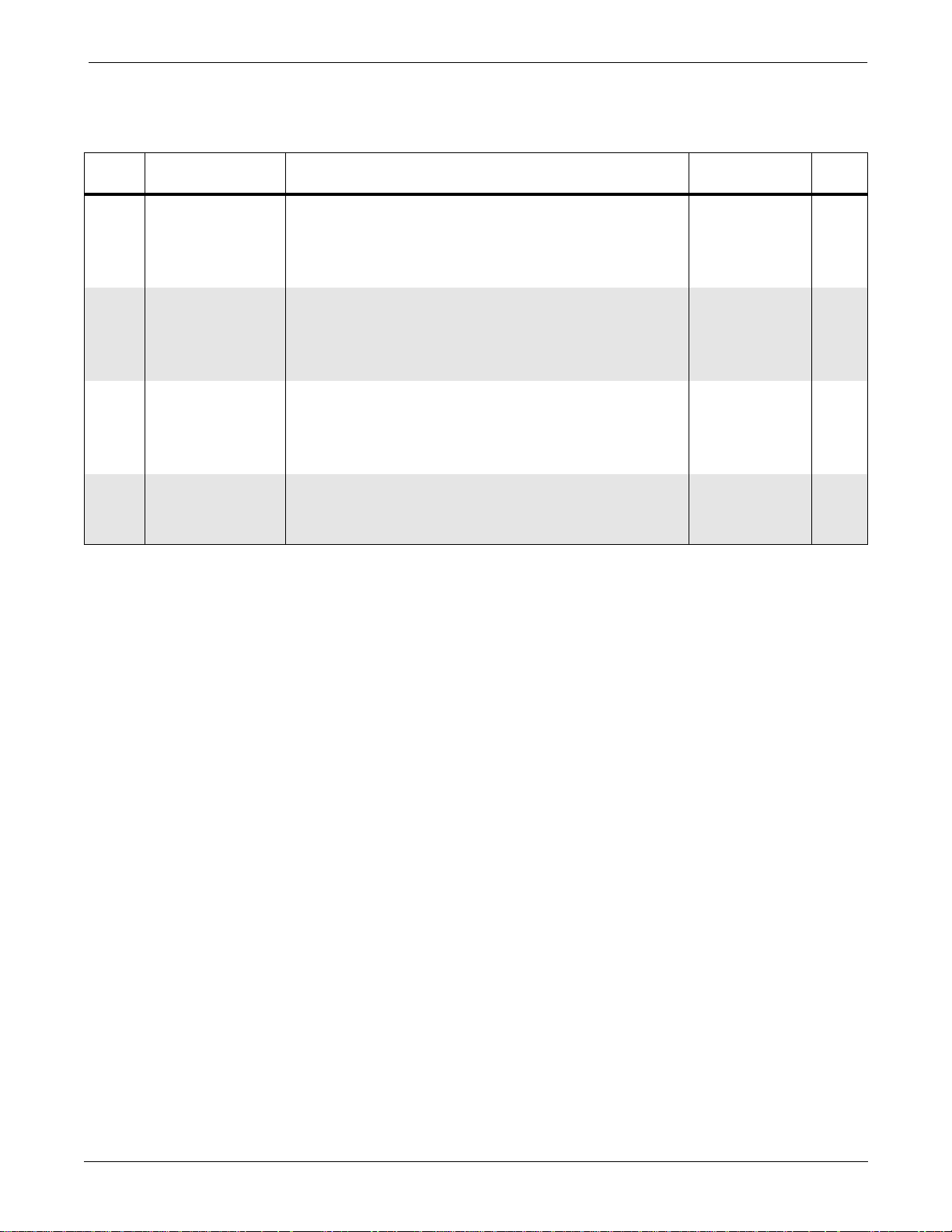
POWER SUPPLY ASSEMBLY AND PCB: Parts List PN 414641-001C
Parts List PN 414641-001C
Item
1 J1 Connector, 3-Pin, w/Locks 1852-003 1
2 Contact, Connector, 18-24 AWG 1853-101 2
3 A1 Power Inlet Module 414629-002 1
4 W3 Choke Assembly, Ground Wire 415239-001 1
5 Bracket, Power Supply 415317-001 1
6 Screw, PNH, Phillips, 4-40 x 3/8 45000-406 2
7 Screw, BDGH, Phillips, 6-32 x 3/8 45074-612 7
8 Washer, Lock, External Tooth, No 4 4520-304 1
9 Nut, Hex, 4-40 4521-304 1
10 Nut, Keps, Hex, 4-40 4521-704 1
11 Tie Wrap 4535-001 1
12 Tubing, Heat Shrink, 3/16 4882-104 AR
13 W2 Wire, 18 AWG (Blue) 4888-006 AR
14 W1 Wire, 18 AWG (Brown) 4888-007 AR
15 A2 Main Power Supply PCB Assembly 800706-001 1
Reference
Designation
Parts List Part Number Qty
Revision A
Eagle 3000 Patient Monitor
415397-038
3-5
Page 67
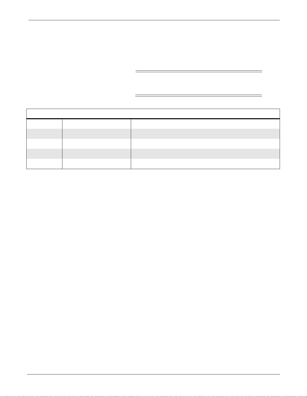
WARNING
POWER SUPPLY ASSEMBLY AND PCB: Switches and Controls PN 800706-001C
Switches and Controls PN 800706-001C
Listed below are all switches, controls, and LEDs found on the
circuit board.
Due to possible high voltage, always use an
insulated screwdriver while making adjustments.
Table 3-1. Switches and Controls
Designator Name Function
R6 +12V ADJ Adjust +12 main output voltage
R8 FREQ ADJ Adjust supply operating frequency
R66 +5V ADJ Adjust +5 output voltage
SW1 115V/230V Line input range select
3-6
Eagle 3000 Patient Monitor
415397-038
Revision A
Page 68
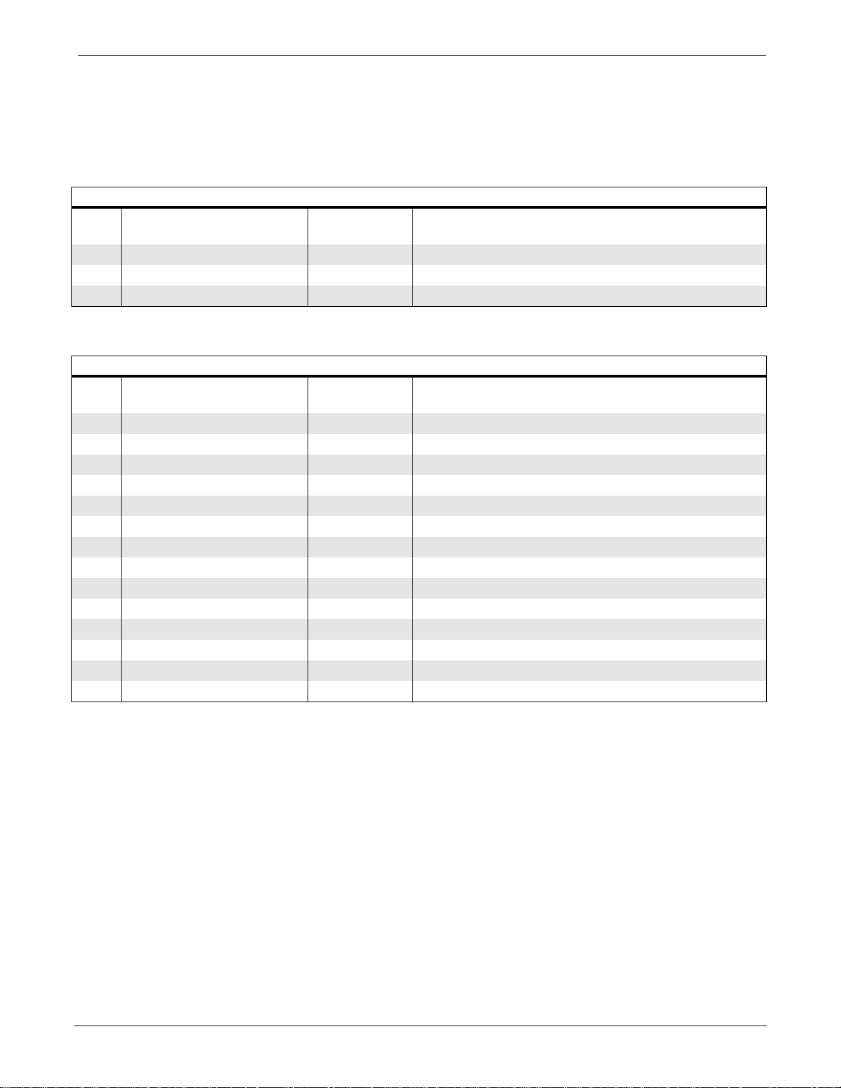
POWER SUPPLY ASSEMBLY AND PCB: PCB Connectors PN 800706-001C
PCB Connectors PN 800706-001C
Pin-by-pin descriptions and the signal names for each internal
PCB connector are described below.
Table 3-2. Connector J1 (3-Pin AC Mains Power Input Connector)
Pin Name
1 NEUTRAL I AC mains power
2NC
3 LINE I AC mains power
Table 3-3. Connector J3 (14-Pin DC Output Connector)
Pin Name
1 NC
2 +12V O +12 V power output
3 +12V O +12 V power output
4 PWRGND - Common ground reference
5 PWRGND - Common ground reference
6 PWRGND - Common ground reference
7 +5V O +5 V power output
8NC -
9 +12V O +12 V power output
10 +12V O +12 V power output
11 PWRGND - Common ground reference
12 PWRGND - Common ground reference
13 PWRGND - Common ground reference
14 +5V O +5 V power output
Input/
Output
Input/
Output
Description
Description
Revision A
Eagle 3000 Patient Monitor
415397-038
3-7
Page 69
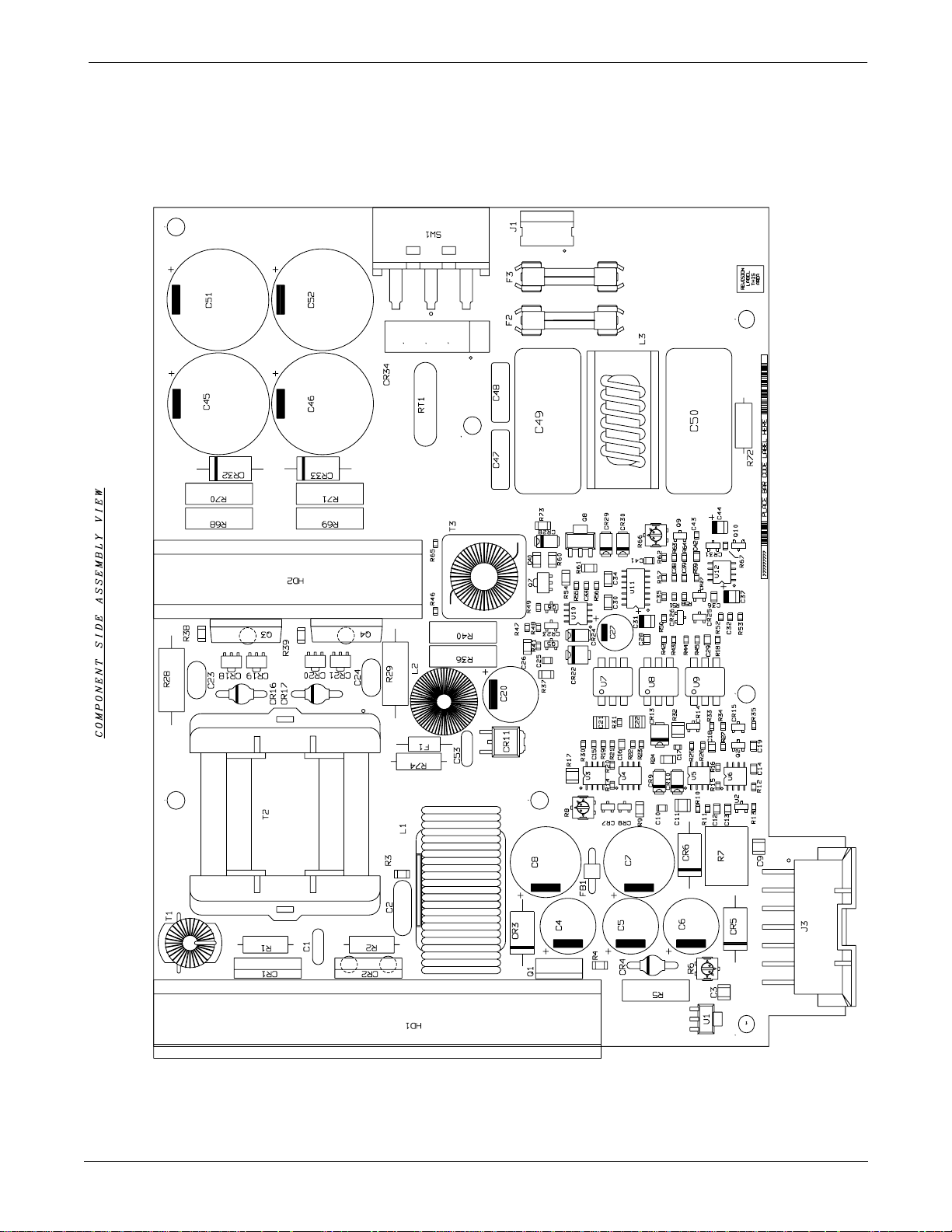
POWER SUPPLY ASSEMBLY AND PCB: Parts Location Diagram PN 800706-001C
Parts Location Diagram PN 800706-001C
Page 1 of 2
3-8
Eagle 3000 Patient Monitor
415397-038
Revision A
Page 70
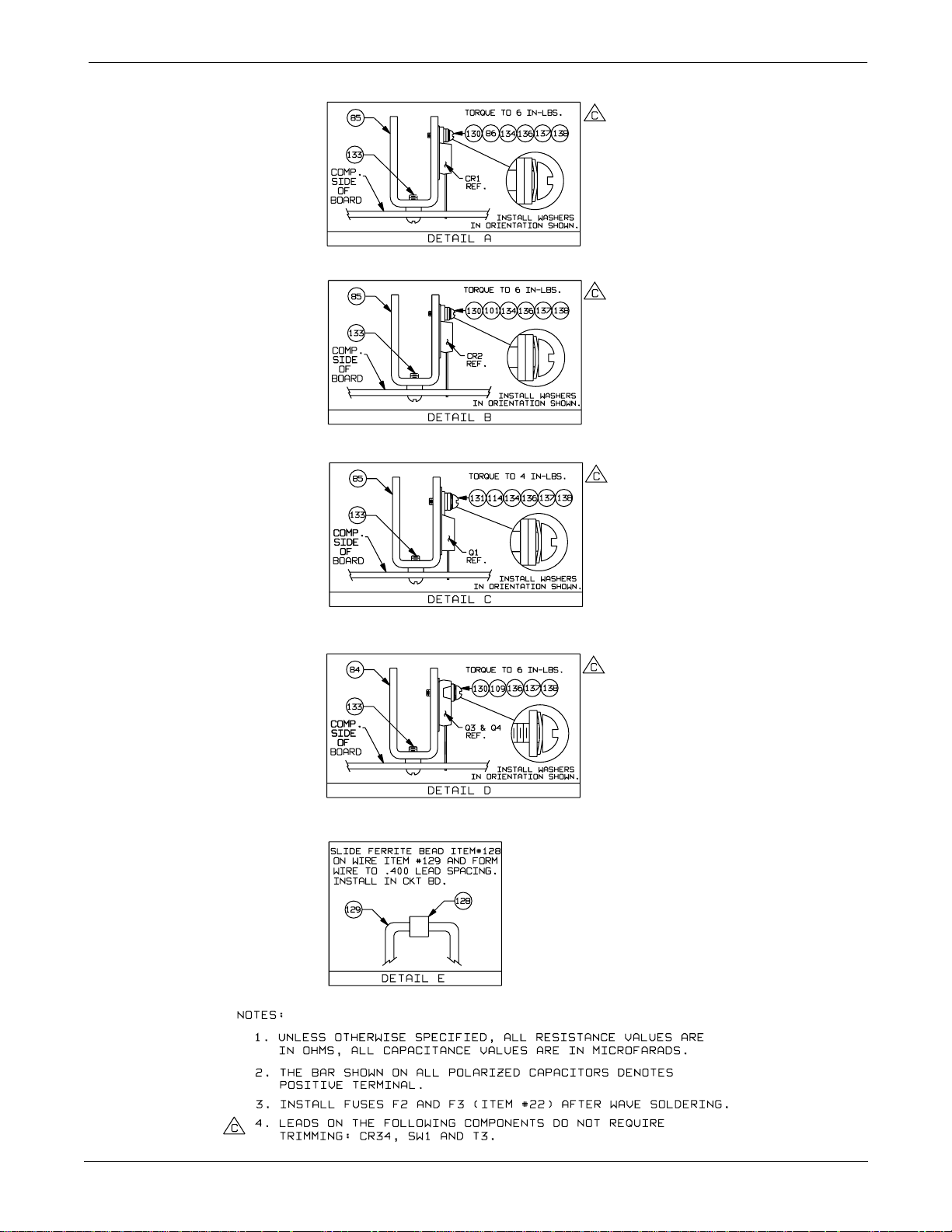
Page 2 of 2
POWER SUPPLY ASSEMBLY AND PCB: Parts Location Diagram PN 800706-001C
Revision A
Eagle 3000 Patient Monitor
415397-038
3-9
Page 71
POWER SUPPLY ASSEMBLY AND PCB: Parts List PN 800706-001C
Parts List PN 800706-001C
Reference
Designation
C1 Cap, Cer, Radial, 0.0022
C2 Cap, Cer, 0.0022
C3, 9, 21, 22 Cap, Cer, 0.22
C4, 5, 6 Cap, Al, 1200
C7, 8 Cap, Al, 2700
C10 Cap, Cer, 470pF, 5%, 50V, SM 1181-471 1
C11 Cap, Cer, 0.01
C12, 13, 14, 16, 18,
19, 25, 36, 42
C15, 35 Cap, NPO, 10pF, +/-0.25pF 411576-010 2
C17 Cap, Cer, 560pF, 5%, 50V 411575-008 1
C20 Cap, Al, 820
C23, 24 Cap, Cer, Radial, 220pF, 10%, 2KV 414163-001 2
C26, 30, 34 Cap, Cer, 0.1
C27 Cap, AL, Radial, 100
C28 Cap, Cer, 0.027
C29 Cap, Cer, X7R, 0.001
C31, 37, 44 Cap, Tant, 4.7
C32 Cap, Cer, 0.1
C33, 43 Cap, Cer, 0.1
C38 Cap, Cer, 0.022
C39 Cap, Cer, 180pF, 5%, 50V 411575-011 1
C40 Cap, Cer, 0.033
C41 Cap, Cer, 820 pF, 1%, 50V, SM 1183-682 1
C45, 46, 51, 52 Cap, Al, 330
C47, 48 Cap, MPE, 2200pF, 20%, 250V 414311-001 2
C49, 50 Cap, MPE, 0.68
C53 Cap, Cer, Radial, 680pF, 10%, 1kV 415572-001 1
CR1 Rectifier Pair, Schottky, 45V, 30A PBYR3045PT 412961-002 1
CR2 Rectifier Pair, 200V, 30A BYV72E-200 413898-001 1
CR3 Diode, Transient Voltage Supressor 1.5KE8.2A 414113-001 1
CR4, 16, 17 Bridge Rectifier, Diode, 3A, 600V BYW95C 414112-001 3
CR5 Diode, Transient Voltage Supressor, 6.8V, 5W
CR6 Transient Voltage Suppressor, 16V, 10%, 1N6276 410936-001 1
CR7, 8, 23, 25, 26, 31 Diode Pair, Series, SM D7000 2013-201 6
CR9, 10, 24 Diode, Rectifier, 1A, 100V, SM MURS110T3 403190-001 3
CR11 Rectifier Pair, 200V, 3A, SM MURD620CTT4 408881-001 1
CR13 Diode, Zener, SM 1SMB5918BT3 414182-001 1
CR14, 27 Diode, Schottky, SM BAT54 401985-001 2
CR15 Diode, Zener, 6.4V, SM BZX84C6V8 403937-003 1
Cap, Cer, 0.1
1N6267A
µ
µ
µ
µ
µ
µ
Description Part Number Qty
µ
F, 10%, 500V 415448-001 1
µ
F, 10%, 1KV 413874-001 1
µ
F, 5%, 50V, SM 1182-224 4
µ
F, 20%, 16V 404316-002 3
µ
F, 20%, 25V 405258-003 2
µ
F, 10%, 100V, SM 403029-001 1
F, 25V 410527-001 9
F, 20%, 35V 404314-002 1
F, 20%, 50V 404370-001 3
µ
F, 20%, 15V 413207-001 1
µ
F, 5%, 50V, SM 1182-273 1
µ
F, SM 1182-102 1
µ
F, 20%, 10V, SM 1176-475 3
F, 5%, 16V 411575-002 1
F, 5%, 50V, SM 411575-012 2
µ
F, 5%, 16V, SM 411575-014 1
µ
F, 5%, 50V, SM 1182-333 1
F, 20%, 250V 413880-001 4
µ
F, 20%, 250V 414980-001 2
413456-001 1
3-10
Eagle 3000 Patient Monitor
415397-038
Revision A
Page 72
POWER SUPPLY ASSEMBLY AND PCB: Parts List PN 800706-001C
Reference
Designation
Description Part Number Qty
CR18, 19, 20, 21 Diode, Zener, 16V, SM BZV49C16 414237-001 4
CR22 Diode, Transient Voltage Supressor, 22V SMB 414348-001 1
CR28, 29, 30 Diode, Schottky, Barrier, 1A, 40V, SM MBRS140T3 403187-001 3
CR32, 33 Diode, Transient Voltage Supressor 1.5KE250A 413901-001 2
CR34 Rectifier Bridge, 800V, 6A KBV8K 414020-001 1
F1 Fuse, 0.5A. SB, Pico-Axial 406911-007 1
F2, 3 Fuse, 4.0A, SB 1908-506 2
HD1 Heatsink, Secondary 412863-002 1
HD2 Heatsink, Primary 412863-001 1
J1 Connector, Header, 3-Postion 414397-001 1
J3 Connector, Header, Right Angle Minifit, BMI, 14-
413798-001 1
Pin
L1 Inductor, Coupled, 2-Sec 413876-001 1
L2 Inductor, 3.3 mH 413877-001 1
L3 Inductor, Common Mode 414312-001 1
Q1 Transistor, PWR, PNP MJE1123 414123-001 1
Q2, 10 Transistor, NPN, SM T3904 2511-001 2
Q3, 4 Transistor, MOS-FET, N-Channel IRFP440 414064-001 1
Q5 Transistor, MOS-FET, N-Channel, SM 2N7002 402414-001 1
Q6 Transister, PNP, Low-Noise, SM 404942-001 1
Q7 Transistor, NPN, SM BCX56-1 2712-056 1
Q8 Transistor, MOS-FET, P-Channel IRFL9014 414065-001 1
Q9 Transistor, PNP, SM T3906 2511-101 1
R1, 2 Res, Comp, 10
R3 Res, Cer, 249
R4 Res, Cer, 332
R5, 36 Res, PWR, MF, 20
Ω
, 5%, 1/2W 1002-100 2
Ω
, 1%, 1/8W, SM 1082-793 1
Ω
, 1%, 1/8W, SM 1082-884 1
Ω
, 1%, 3W 413730-004 2
R6 Res, Var, 1K, Vert, Top-Adjust 403938-003 1
R7 Res, Power, Standup, 75
Ω
, 5%, 5W 414063-001 1
R8, 66 Res, Var, 2K, Top Adjust 403938-001 2
R9 Res, Cer, 619
Ω
, 1%, 1/8W, SM 1082-866 1
R10 Res, Cer, 45.7K, 1%, 1/16W, SM 410334-036 1
R11, 12, 16, 35, 58 Res, Cer, 10K, 1%, 1/16W, SM 410334-013 5
R13 Res, Cer, 9.09K, 1%, 1/16W, SM 410334-012 1
R14 Res, Cer, 17.8K, 1%, 1/16W, SM 410334-088 1
R15, 46, 53, 65 Res, Cer, 4.99K, 1%, 1/16W, SM 410334-066 4
R17 Res, Cer, 330
Ω
, 5%, 1/4W 415169-001 1
R18, 64 Res, Cer, 2K, 1%, 1/16W, SM 410334-009 2
R19, 25 Res, Cer, 49.9K, 1%, 1/16W, SM 410334-094 2
R20, 21 Res, Cer, 6.49K, 1%, 1/16W, SM 410334-083 2
R22, 45, 48 Res, Cer, 1K, 1%, 1/16W, SM 410334-008 3
R23 Res, Cer, 301
Ω
, 1%, 1/16W, SM 410334-073 1
R24 Res, Cer, 10K, 1%, 1/8W, SM 1082-104 1
R26, 50, 63 Res, Cer, 100
Ω
, 1%, 1/16W, SM 410334-003 3
Revision A
Eagle 3000 Patient Monitor
415397-038
3-11
Page 73
POWER SUPPLY ASSEMBLY AND PCB: Parts List PN 800706-001C
Reference
Designation
Description Part Number Qty
R27 Res, Cer, 35.7K, 1%, 1/16W, SM 410334-091 1
R28, 29 Res, Comp, 240
R30 Res, Cer, 511
Ω
, 5%, 1W 1003-241 2
Ω
, 1%, 1/16W, SM 410334-034 1
R31 Res, Cer, 4.42K, 1%, 1/16W, SM 410334-093 1
R32 Res, Cer, 68.1K, 1%, 1/4W, SM 407468-013 1
R33, 34, 44 Res, Cer, 619
R37 Res, Cer, 100
R38, 39 Res, Cer, 22.1
R40 Res, PWR, MF, 0.649
Ω
, 1%, 1/16W, SM 410334-092 3
Ω
, 1%, 1/8W, SM 1082-755 1
Ω
, 1%, 1/8W, SM 1082-804 2
Ω
, 1%, 3W 413730-005 1
R41 Res, Cer, 100K, 1%, 1/16W, SM 410334-019 1
R42 Res, Cer, 30.1
Ω
, 1%, 1/16W, SM 410334-109 1
R43 Res, Cer, 3.01K, 1%, 1/16W, SM 410334-018 1
R47 Res, Cer, 23.7K, 1%, 1/16W, SM 410334-108 1
R49, 59 Res, Cer, 20.0K, 1%, 1/16W, SM 410334-053 2
R51 Res, Cer, 30.1K, 1%, 1/16W, SM 410334-095 1
R52 Res, Cer, 1.50K, 1%, 1/16W, SM 410334-080 1
R54 Res, Cer, 1K, 1%, 1/8W, SM 1082-103 1
R55, 57 Res, Cer, 22.6K, 1%, 1/16W, SM 410334-089 2
R56 Res, Cer, 200K, 1%, 1/16W, SM 410334-022 1
R60 Res, Cer, 2K, 1%, 1/8W, SM 1082-201 1
R61 Res, Cer, 73.2
Ω
, 1%, 1/8W, SM 1082-848 1
R62 Res, Cer, 6.19K, 1%, 1/16W, SM 410334-121 1
R67 Res, Cer, 21.5K, 1%, 1/16W, SM 410334-086 1
R68, 69 Res, PWR, MF, 150K, 1%, 3W 413730-002 2
R70, 71 Res, PWR, MF, 12.8K, 1%, 3W 413730-001 2
R72 Res, Comp, 330K, 5%, 1/2W 1002-334 1
R73 Res, Cer, 15
R74 Res, Comp, 33
RT1 Thermistor, 2.5
Ω
, 1%, 1/8W, SM 1082-811 1
Ω
, 5%, 1/2W 1002-330 1
Ω
, 8A 406067-004 1
SW1 Switch, Slide, DPDT, 115-230V 414010-001 1
T1 Transformer, Current Sense 413879-001 1
T2 Transformer, Power, High Frequency 413881-001 1
T3 Transformer, Gate Drive 413878-001 1
U1 Volt Rgltr, +5V, SM LT1123CST 412454-002 1
U2 Voltage Reference, Shunt, SM LM4040 411568-002 1
U3, 4 Volt Rgltr, SM TL431ACD 403046-001 2
U5, 6 Volt Comparator, Dual LM393 3144-393 2
U7, 9 Isolator, Optically Coupled MOC8102T 413900-001 2
U8 Isolator, Optically Coupled MOC3012T 414023-001 1
U10 Volt Rgltr, Adj, SM LP2951A 3076-001 1
U11 Pulse Width Modulator, SM VC3844AD 413899-001 1
U12 Timer, SM LM555CM 414116-001 1
– Ferrite Bead (item 128 for leads 1 and 3 of CR2, for
411169-001 5
center lead of Q3 and Q4, and for wire, item 129)
3-12
Eagle 3000 Patient Monitor
415397-038
Revision A
Page 74
POWER SUPPLY ASSEMBLY AND PCB: Parts List PN 800706-001C
Reference
Designation
Description Part Number Qty
– Wire Bus, 16 AWG (item 129) 4900-010 1
– Pad, Silicon (item 130 for CR1, CR2, Q3, and Q4) 414630-001 2
– Insulator, TO220 (item 131 for Q1) 3952-006 1
– Screw, PNH, Phillips, SST, 6-32 x 3/8 (item 133 for
4502-612 4
CR1, CR2, Q1, Q3, and Q4)
– Washer, Shoulder, Nylon (item 134 for CR1, CR2,
4538-104 3
and Q1)
– Holder, Fuse Clip (item 135 for F3) 401181-001 4
– Washer, Flat, SST, No 4 (item 136 for CR1, CR2,
4520-004 5
Q1, Q3, and Q4)
– Washer, Belleville (item 137 for CR1, CR2, Q1, Q3,
4550-806 5
and Q4)
– Screw, PNH, Phillips, SST, 4-40 x 3/8 (item 138 for
4502-412 5
CR1, CR2, Q1, Q3, and Q4)
– Circuit Board 800707-001 1
– Schematic Diagram SD800706-001B 1
Revision A
Eagle 3000 Patient Monitor
415397-038
3-13
Page 75
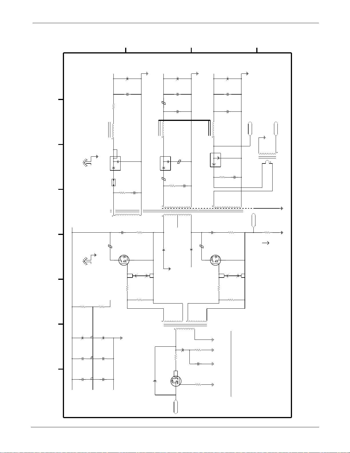
POWER SUPPLY ASSEMBLY AND PCB: Schematic Diagram PN SD800706-001B
Schematic Diagram PN SD800706-001B
1 of 6
D
C
B
A
20%
20%
C2
0.0022
10%
1KV
16
4
CR16
+V
COM
BYW95C
+6V
14
L1
23
PBYR3045PT
CR1
10
2KV
C24
220PF
B4
Q4
2
CR3
1
1
R1
10
5%
1/2W
10%
IRFP440
3
1
CR20
21
1.5KE8.2A
2
C5
1200+16V
C4
1200+16V
R29
1W
C16
BZV49
3
C53
10%
3
21
20%
680PF
CR18
BZV49
1KV
R28
1W
3
1
240
5%
C16
CR19
3
PWR
+12V
CR6
1
C7
C16
BZV49
12
FB1
L1
CR2
BYV72E-200
C8
32
23
1
B1
R2
10
5%
1/2W
14
6
8
CR17
BYW95C
PWR
1.5KE16A
2
2700+25V
2700+25V
B2
NC
+VBIAS
CR22
P6SMB22AT3
2
1
C20
820+35V
20.0
R363W1%
L2
36
PWR
4
2
HD2HD1
CR11
+V
COM
MURD620CT
3
0.5ASB
F1
2
T2
B3
2
1
R74
33
5%
1/2W
C23
220PF
Q3
IRFP440
1
2KV
10%
20%
20%
C1
0.0022
10%
240
5%
CR21
3
500V
12
C16
BZV49
12
COM
+6SWV
9
4
T1
2
IPSEN+
SCOM
R40
3W
Ipri
3
1
0.649
1%
ISSEN+
COM
PWR
3-14
R70
32.8K
R71
3W
1%
3W
CR32
1.5KE250A
CR33
2
1
C45
C51
8 76543 21
+VH
20%
330+250V
20%
330+250V
1
C46
C52
VMD
+IBOOT
32.8K
1%
1.5KE250A
2
20%
330+250V
20%
330+250V
-VH
22.1
R381%1/8W
PWR
R65
4.99K
CR29
3
T3
10MQ040
1
15.0
R731%1/8W
2
IRFL9014
Q8
3
CR28
4
G_DRV
4
5
10MQ040
1
Eagle 3000 Patient Monitor
415397-038
22.1
R391%1/8W
R46
4.99K
6
2
R60
C40
R61
1%
1%
2K
0.033
73.2
1/8W
1/8W
PWR
PWR PWR PWR
NOTES:
1) B1,B2 FERRITE BEAD, FAIR-RITE CORP.
#2643001501 PLACED ON CR2
ANODES AS SHOWN
2) B3,B4 FERRITE BEAD, FAIR-RITE CORP.
#2643001501 PLACED ON THE
DRAIN OF Q3 AND Q4 AS SHOWN.5)#2643001501 PLACED ON 16 AWG
Q3,Q4 MOUNT TO HEATSINK HD1
CR1,CR2,Q1 MOUNT TO HEATSINK HD2
3)
4)
BUS WIRE.
FB1 FERRITE BEAD, FAIR-RITE CORP.
Revision A
Page 76
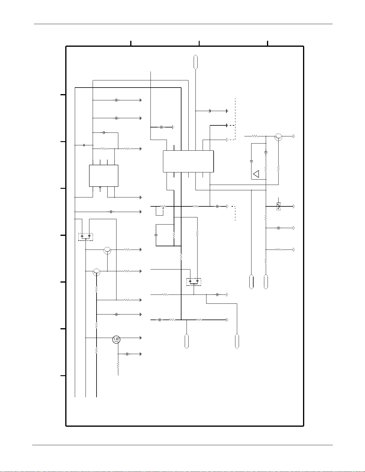
POWER SUPPLY ASSEMBLY AND PCB: Schematic Diagram PN SD800706-001B
2 of 6
CR24
2
10MF2
LP2951
U10
1
3
1
+VIN
8
R48
VOUT
D7000
CR23
Q6
1K
D
50V
20%
C34
0.1
20%
C27
100+35V
C33
0.01
R56
200K
NC3
236
5V
SENSE
ERRORSDGND FB
5
NC1 NC2
Q7
3
2
T5087
312
R55
22.6K
47
50V
20%
C30
0.1
BCX56-10
R54
1K
1
1%
1/8W
R49
20K
R47
23.7K
PWR PWR
PWR PWRPWR
PWR
PWR
PWR
VREF
VREF
VREFVREF
VREF
FREQ
C35
C
C31
4.7+16V
UC3844AD
U11
ADJ
R66
1
2CWDN
10PF
+/-.25PF
R59
20%
CTRL
NCNC
141312
NC
REF
NC
COMP
1
2
20%
2K
3
100V
30.1K
R51
10K
R58
20K
3
VCCVFB
11
10
VC
NC
4
5
NC
R62
R50
2
3
G_DRV
CR30
10MQ040
9
GND
OUT
C/SNCR/C PGND
6
78
NC
50V
1%
C41
D7000
CR26
C42
820PF
20%
25V
0.1
7.32K
100
1
B
PWR PWR
CTRL CTRL
SINGLE PT GND TO
CTRL
SINGLE PT GND
UC3844 GND PIN 9
VREF
C39
R64
2K
180PF
OVPSD
A
Q9
T3906
CTRL
312
C38
16V 5%
0.022
100
R63
22.6K
R57
B
NC
1
BAT54
CR27
CTRL
2
3
1K
R45
C29
.001
CTRL
CTRL
R18
2K
100
R37
1/8W
1%
IPSEN+
Revision A
150K
R693W1%
150K
R683W1%
8 76543 21
+VBIAS
+V
+IBOOT
3
Q5
R41
C26
0.1
2N7002
1
100K
VREF
50V
2
20%
C25
0.1
25V
PWR
C28
0.027
R42
30.1
PWR
20%
PWR
Eagle 3000 Patient Monitor
415397-038
FBDR
R43
3.01K
CTRL
FLTSD
3-15
Page 77
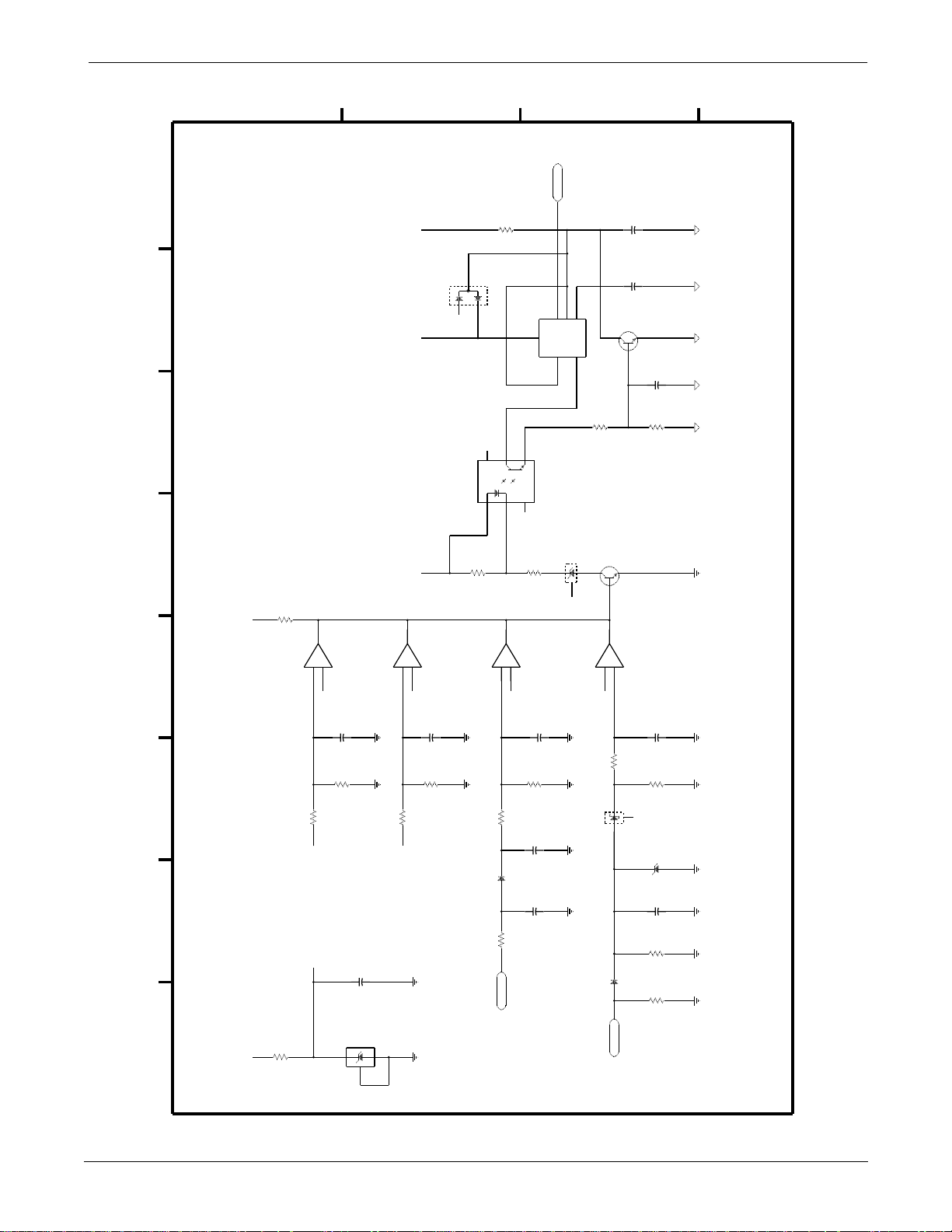
POWER SUPPLY ASSEMBLY AND PCB: Schematic Diagram PN SD800706-001B
of 6
A
FLTSD
765
DIS
TR
2
THR
B
20%
C44
4.7+16V
C43
0.01
Q10
R52
1.5K
T3904
2
3
1
C32
R53
CV
OUT
3
10%
16V
0.1
4.99K
CTRLCTRL
CTRLCTRL CTRL
D
C
R67
21.5K
D7000
CR31
3
1
2
NC
U9
MOC8102T
6
1
LM555CM
U12
4
R
NC
5
4
NC
NC
3
2
NC
+12V
8 76543 21
+12V
R16
R15
10K
U6
4.99K
1
LM393
3
9.09K
R13
+5V
+2.5V +
-
2
+2.5V
C14
R12
2
0.1
10K
25V
C13
U2
1
20%
U6
SCOM SCOM
25V
20%
0.1
LM4040
3
LM393
5
35.7K
R27
7
+
6
+12V
+12V VREF VREF
-
+2.5V
SCOM
SCOM
C19
R35
0.1
10K
25V
20%
R33
SCOM SCOM
619
LM393
U5
R10
3
47.5K
CR10
249R31%
1
+
-
2
+2.5V
10MF2
+6SWV
1/8W
R34
R11
C11
C10
619
C12
0.1
10K
100V
0.01
100V
470PF
25V
10%
5%
20%
CR15
BZX84C6V8
3
2
NC
COM
COM SCOM SCOM
1
U5
Q2
3
1
7
+
LM393
5
+2.5V
R26
CR141BAT54
CR9
T3904
-
6
100
32
ISSEN+
2
NC
10MF2
C18
0.1
R25
49.9K
CR13
1SMB5918
1
C17
560PF
R32
68.1
R24
10K
1%
1/8W
25V
2
1/4W
SCOM
20%
SCOM SCOM
1%
SCOM SCOM SCOM SCOM
3-16
Eagle 3000 Patient Monitor
415397-038
Revision A
Page 78
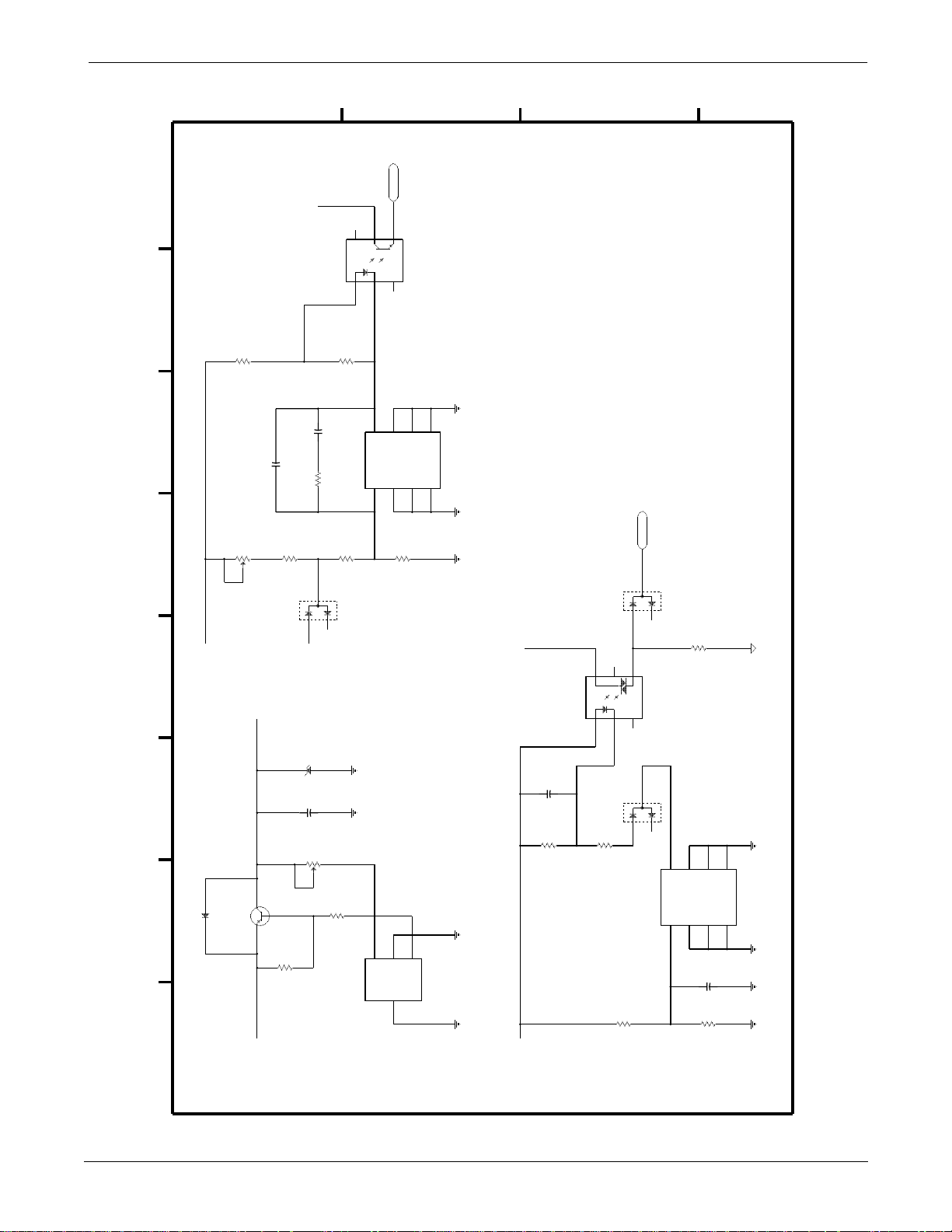
POWER SUPPLY ASSEMBLY AND PCB: Schematic Diagram PN SD800706-001B
4 of 6
+12V
+12V
ADJ
3
R17
5%
R8
2
330
1/4W
2K
1
CW
D
20%
UP
C15
10PF
+/-.25PF 100V
R14
R19
17.8K
1
VREF
C21
49.9K
3
+5V
2
U7
0.22
D7000
CR7
NC
NC
6
NC
MOC8102T
1
R30
511
TL431ACD
U3
R20
6.49K
5
2
1
8
CATH
REF
C
FBDRNC
4
NC
3
6
7
5
AN
AN
NC
NC
AN
AN
4
3
2
R21
6.49K
SCOM SCOM SCOM
VREF
B
OVPSD
D7000
CR25
3
1
2
NC
R44
619
NC
5
6
4
A
CTRL
+5V+6V
+5V
Q1
MJE1123
1
32
CR4
BYW95C
8 76543 21
ADJ
R4
1%
CR5
1
C6
3
332
1/8W
1.5KE6.8A
2
1200+16V
20%
20%
R6
1K
1
UP
2
CW
R5
20.0
3W
1%
COM COM
3
FB
LT1123CST
U1
U8
MOC3012T
C22
0.22
R23
301
2
1
DRV
GND
GND
4
COM COM
+12V
NC
1
3
2
NC
D7000
CR8
3
1
2
R9
619
NC
6
7
R31
4.42K
1
TL431ACD
U4
8
CATH
REF
5
AN
AN
NC
NC
AN
AN
4
3
2
25V
20%
C16
0.1
R22
SCOM SCOM SCOM SCOM
1K
1%
1/8W
Revision A
Eagle 3000 Patient Monitor
415397-038
3-17
Page 79
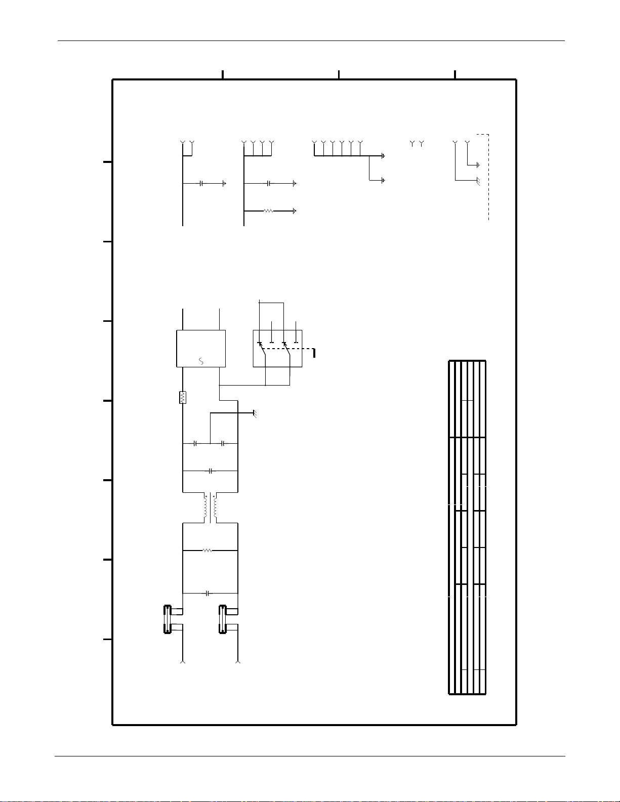
POWER SUPPLY ASSEMBLY AND PCB: Schematic Diagram PN SD800706-001B
5 of 6
SUPPLY OUTPUTS
D
CR34
KBU8K
RT1
-J37-J3
+5V
+VH
1
V+
AC
3
CL-30A
14
2.5 OHM
C47
2200PF
C3
0.22
250V
20%
-VH
4
V-AC
2
C48
COM
250V
20%
2200PF
-J32-J33-J39-J3
C9
0.22
R7
75
5W
5%
+12V
VMD
1a
1b
SW1
4021.4711
1
/16V 20%
C37 4.7
COM
COMMON TO CHASSIS
MOUNTING HOLES
A
C
10
NC
2a
4
11
-J3
-J3
-J35-J36-J312-J3
COMCOM
NC
2b
2
115V
230V
B
13
COMSCOM
-J31-J3
NC
8
NC
1
TL8 -1TL4 -
20%
BYPASS
POWER SUPPLY
4.0A
F3
12 3 4
L
8 76543 21
AC INPUT
20%
250V
C49
0.68
4
L3
23
1
330K5%
1/2W R72
250V
20%
C50
0.68
IC POWER/RETURN CHART
4.0A
F2
12 3 4
N
J1 3-
J1 1-
IC POWER RETURN
U6 LM393 +12V SCOMGND84
U5 LM393 +12V SCOMGND84
U12 LM555CM VREF CTRLGND81C36 0.1/25V
3-18
Eagle 3000 Patient Monitor
415397-038
Revision A
Page 80
POWER SUPPLY ASSEMBLY AND PCB: Schematic Diagram PN SD800706-001B
of 6
J1-1: N
J1-3: L
CONNECTOR SIGNAL
J3-2: +12V
J3-3: +12V
J3-4: COMGND
D
J3-7: +5V
J3-5: COMGND
J3-6: COMGND
J3-9: +12V
J3-10: +12V
J3-11: COMGND
J3-14: +5V
J3-12: COMGND
J3-13: COMGND
C
B
A
Revision A
5-A8
U1: 4-C8
U2: 3-D8
U3: 4-C4
U4: 4-B7
U5: 3-B5,C5
REFDES PAGE COORDINATES
3-C4,C7,D5,D8
4-C8,D5
5-C2
4-D5
+12V: 1-C1
LABEL PAGE COORDINATES
+5V: 3-D7
+2.5V: 3-B5,C5,D5,D7
8 76543 21
5-A8
U6: 3-C5,D5
5-D2
+6SWV: 1-B2
U7: 4-D2
3-C8
U8: 4-B5
+6V: 1-B1
4-D8
U9: 3-C4
+IBOOT: 1-D6
5-A8
U10: 2-D4
U11: 2-C3
U12: 3-B2
2-D8
2-D8
2-D8
5-D3
5-D3
+V: 1-C5,D4
+VBIAS: 1-D1
+VH: 1-D8
-VH: 1-D8
FBDR: 2-C7
Eagle 3000 Patient Monitor
415397-038
4-C1
FLTSD: 2-B7
3-B1
G_DRV: 1-C8
2-C1
IPSEN+: 1-B4
2-B6
ISSEN+: 1-A2
3-B8
L: 5-D8
N: 5-C8
2-B6
4-B4
OVPSD:
1-D8
5-C3
2-B2,C1,C4,C5,C6,D8
3-C1,C2
4-C5,D1
VMD:
VREF:
3-19
Page 81

For your notes
POWER SUPPLY ASSEMBLY AND PCB: Schematic Diagram PN SD800706-001B
3-20
Eagle 3000 Patient Monitor
415397-038
Revision A
Page 82

4
OPTION ASSEMBLIES AND
PCBs
Introduction ...........................................................................4-2
Exploded View PN 416021-001C/002C ................................... 4-3
Parts List PN 416021-001C ....................................................4-5
Parts List PN 416021-002C ....................................................4-6
Exploded View PN 418394-001A/002A ................................... 4-7
Parts List PN 418394-001A ..................................................... 4-9
Parts List PN 418394-002A ................................................... 4-10
Switches and Controls PN 800836-002A ............................... 4-11
PCB Connectors PN 800836-002A ........................................ 4-12
Parts Location Diagram PN 800836-002A ............................. 4-17
Parts List PN 800836-002A ................................................... 4-18
Schematic Diagram PN SD800836-002A ............................... 4-20
Switches and Controls PN 801318-001A ............................... 4-29
PCB Connectors PN 801318-001A ........................................ 4-30
Parts Location Diagram PN 8013138-001A .......................... 4-35
Parts List PN 801318-001A ................................................... 4-36
Schematic Diagram SD801318-001A .................................... 4-38
Switches and Controls PN 800862-001E ............................... 4-47
PCB Connectors PN 800862-001E ........................................ 4-48
Parts Location Diagram PN 800862-001E ............................. 4-50
Parts List PN 800862-001E .................................................. 4-53
Schematic Diagram SD800862-001E .................................... 4-56
Revision A
Eagle 3000 Patient Monitor
415397-038
4-1
Page 83
Introduction
OPTION ASSEMBLIES AND PCBs: Introduction
This chapter presents information about the option assemblies, pn
416021-001C, 416021-002C, 418394-001A, and 418394-002A,
and the option PCBs, pn 800836-002A, 800862-001E, and
801318-001A. The table below gives additional information about
these options.
Option
ETCO2 w/Defib Sync & Remote
1
Alarm
Defib Sync & Remote Alarm
1
1
There are two assemblies for each option. Assembly pn 416021-001C
and 416021-002C and their corresponding PCBs were used in older
Eagle 3000 monitors that have the 1/4-inch phone jack type connector
for remote alarm. Assembly pn 418394-001A and 418394-002A and
their corresponding PCBs are used in new Eagle 3000 monitors, which
have a 9-pin subminiature “D” connector for remote alarm.
Assembly Part
Number
416021-001C
OR
418394-001A
416021-002C
OR
418394-002A
PCB Part Number
800836-002A &
800862-001E
OR
801318-001A &
800862-001E
800836-002A
OR
801318-001A
4-2
Eagle 3000 Patient Monitor
415397-038
Revision A
Page 84
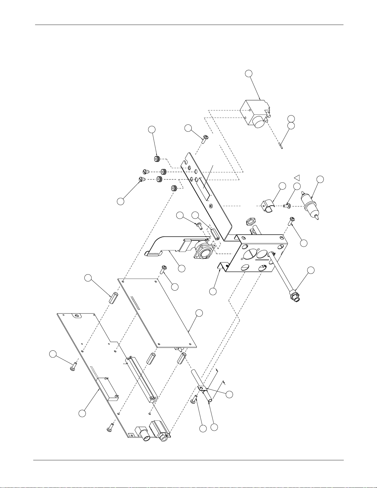
OPTION ASSEMBLIES AND PCBs: Exploded View PN 416021-001C/002C
Exploded View PN 416021-001C/002C
Page 1 of 2
REFER TO
ASSEMBLY
DETAIL A
8
SEE NOTE 1
19
6
REFER TO ASSEMBLY
B
3
13
DETAIL B
2
23
TORQUE 1.5 in-LBS
2 PLCS
9
4 PLCS
17
3 PLCS
12
2 PLCS
10
HERE
PLACE UID LABEL
OF EXHAUST FTG.
JAM NUT IS PART
TORQUE 10 in-LBS
4 PLCS
14
4 PLCS
16
W3
14
22
21
7
1.0 in
11
2 PLCS
15
REFER TO
4
ASSEMBLY
DETAIL B
Revision A
20
1
15
2.75 in.
Eagle 3000 Patient Monitor
415397-038
4-3
Page 85
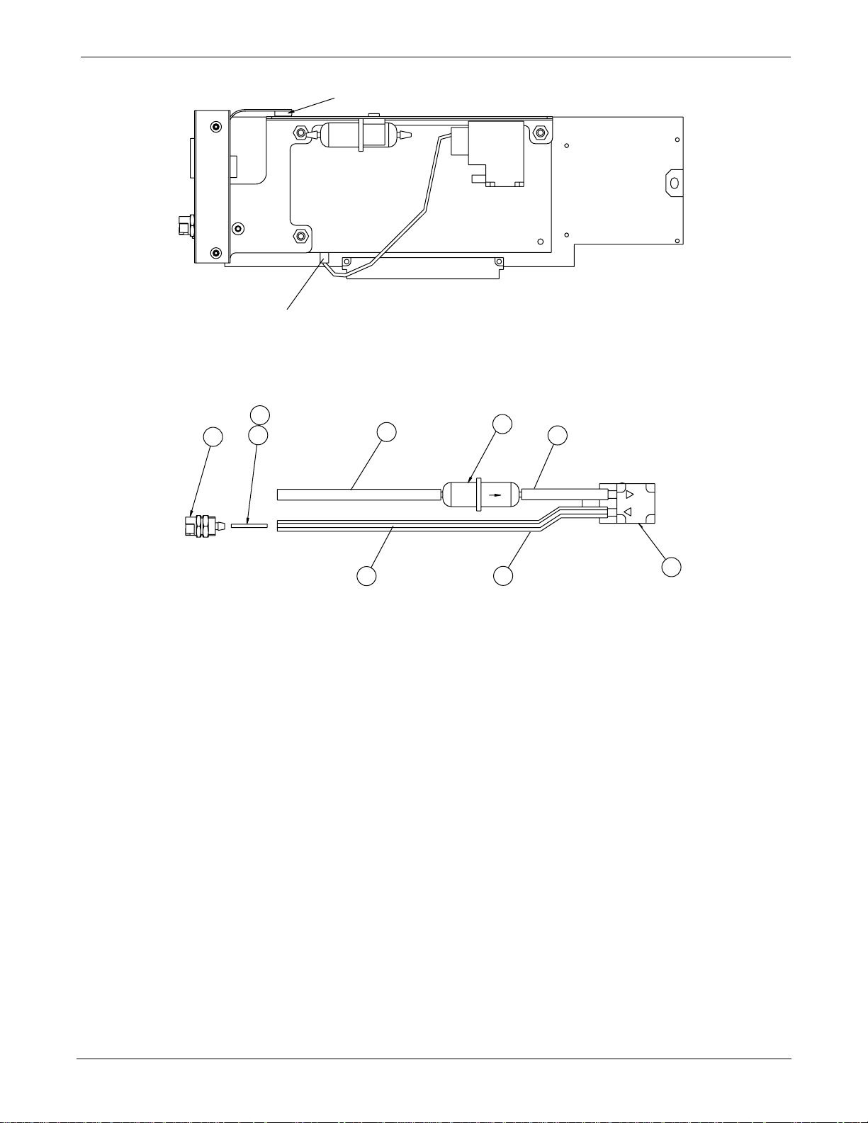
OPTION ASSEMBLIES AND PCBs: Exploded View PN 416021-001C/002C
Page 2 of 2
REF. FLEX CIRCUIT(W3) PLUGS INTO PCB CONNECTOR(J3)
REF. PUMP ASSY PLUG (P1) CONNECTS TO PCB (J4)
ASSEMBLY DETAIL A
19
SEE NOTE 1
4
6
1
4.2 in.
FLOW
2
1
2.5 in.
5
6.3 in ±.10
24
(INNER TUBE)
SEE NOTE 4.
ASSEMBLY DETAIL B
NOTES:
1. APPLY ADHESIVE 360 DEG. ON ITEM 6 FOR GAS SEAL.
2. ASSEMBLE FLEX ASSY ITEM 22 TO BRACKET ITEM 7 FIRST
3. ASSEMBLE TUBE CLAMP ITEM 11 WITH TUBE ITEM 1 TO BRACKET SECOND.
4. ALCOHOL MAY BE USED AS A LUBRICANT IN ASSEMBLING TUBING.
6.6 in ±.10
8
4-4
Eagle 3000 Patient Monitor
415397-038
Revision A
Page 86
OPTION ASSEMBLIES AND PCBs: Parts List PN 416021-001C
Parts List PN 416021-001C
Item
1 Tubing, Silastic 401582-001 AR
2 Filter, 25 Micron, 1/8 Barbs 413049-001 1
3 Clip Component 413337-001 1
4 Coupling, Panel 413757-001 1
5 Tubing, Tygon, 5/32 413779-001 AR
6 Fitting, Barb, SAM Pump 415516-001 2
7 Bracket Assembly, ETCO2 415965-001 1
8 Pump Assembly, Micro-diaphragm, w/
9 Screw, Shoulder 416069-001 2
10 Spacer, Hex, 2-56 x 1.00 416409-001 2
11 Tube Clamp, 0.25 diameter 416410-001 1
12 Screw, PNH, Phillips, 4-40 x 1/2 45000-408 3
13 Screw, BDGH, 4-40 x 0.188 406124-003 1
14 Screw, BDGH, Phillips, 4-40 x 1/4 45074-408 5
15 Screw, BDGH, Phillips, 6-32 x 1/4 45074-608 3
16 Spacer 4603-412 4
17 Screw, BDGH, SST, 2-56 x 3/16 4760-008 1
19 Adhesive, Loctite 4851-089 AR
20 Monitor Options PCB Assembly, 1/4-inch
21 Capnostat CO2 Subsystem PCB Assembly 800862-001 1
22 Flex Circuit, ETCO2 Connector 801014-001 1
23 Grommet Vibration Damper S112-100-001 4
24 Tubing, Tygon, 1/16 ID x 1/8 OD S509-104-002 AR
Reference
Designation
Parts List Part Number Qty
416008-001 1
Connector
800836-002 1
phone jack remote alarm connector
Revision A
Eagle 3000 Patient Monitor
415397-038
4-5
Page 87

OPTION ASSEMBLIES AND PCBs: Parts List PN 416021-002C
Parts List PN 416021-002C
Item
1 Bracket, Connector Mounting 415887-002 1
2 Screw, BDGH, Phillips, 6-32 x 1/4 45074-608 2
3 Monitor Options PCB Assembly, 1/4-inch
Reference
Designation
Parts List Part Number Qty
800836-002 1
phone jack remote alarm connector
4-6
Eagle 3000 Patient Monitor
415397-038
Revision A
Page 88
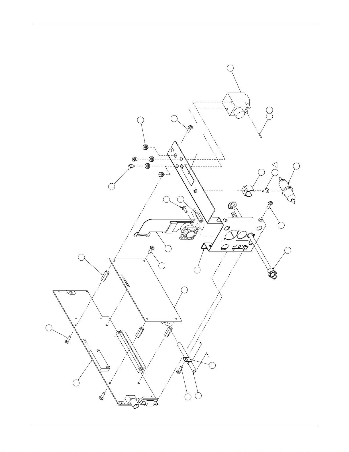
OPTION ASSEMBLIES AND PCBs: Exploded View PN 418394-001A/002A
Exploded View PN 418394-001A/002A
Page 1 of 2
REFER TO
ASSEMBLY
DETAIL A
8
SEE NOTE 1
19
6
REFER TO ASSEMBLY
B
3
13
DETAIL B
2
23
TORQUE 1.5 in-LBS
2 PLCS
9
4 PLCS
17
3 PLCS
12
2 PLCS
10
HERE
PLACE UID LABEL
OF EXHAUST FTG.
JAM NUT IS PART
TORQUE 10 in-LBS
4 PLCS
14
4 PLCS
16
W3
14
22
21
7
1.0 in
11
2 PLCS
15
REFER TO
4
ASSEMBLY
DETAIL B
Revision A
20
1
15
2.75 in.
Eagle 3000 Patient Monitor
415397-038
4-7
Page 89
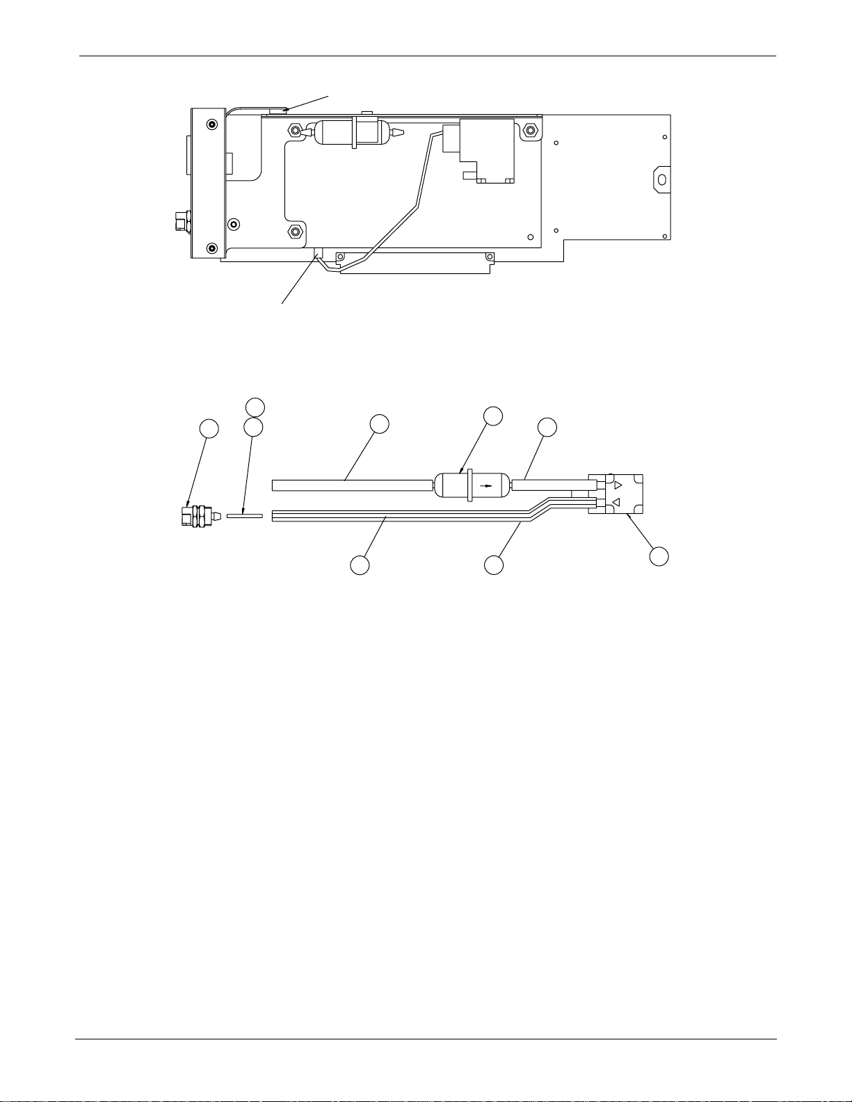
OPTION ASSEMBLIES AND PCBs: Exploded View PN 418394-001A/002A
Page 2 of 2
REF. FLEX CIRCUIT(W3) PLUGS INTO PCB CONNECTOR(J3)
REF. PUMP ASSY PLUG (P1) CONNECTS TO PCB (J4)
ASSEMBLY DETAIL A
19
SEE NOTE 1
4
6
1
4.2 in.
FLOW
2
1
2.5 in.
5
6.3 in ±.10
24
(INNER TUBE)
SEE NOTE 3.
ASSEMBLY DETAIL B
NOTES:
1. APPLY ADHESIVE 360 DEG. ON ITEM 6 FOR GAS SEAL.
2. ASSEMBLE FLEX ASSY, ITEM 22, TO BRACKET ITEM 7, THEN
ASSEMBLE TUBE CLAMP, ITEM 11, WITH TUBE, ITEM 1, TO BRACKET.
4. ALCOHOL MAY BE USED AS A LUBRICANT WHEN INSERTING INNER TUBING.
6.6 in ±.10
8
4-8
Eagle 3000 Patient Monitor
415397-038
Revision A
Page 90
OPTION ASSEMBLIES AND PCBs: Parts List PN 418394-001A
Parts List PN 418394-001A
Item
1 Tubing, Silastic 401582-001 AR
2 Filter, 25 Micron, 1/8 Barbs 413049-001 1
3 Clip Component 413337-001 1
4 Coupling, Panel 413757-001 1
5 Tubing, Tygon, 5/32 413779-001 AR
6 Fitting, Barb, SAM Pump 415516-001 2
7 Bracket Assembly, ETCO2 415965-002 1
8 Pump Assembly, Micro-diaphragm, w/
9 Screw, Shoulder 416069-001 2
10 Spacer, Hex, 2-56 x 1.00 416409-001 2
11 Tube Clamp, 0.25 diameter 416410-001 1
12 Screw, PNH, Phillips, 4-40 x 1/2 45000-408 3
13 Screw, BDGH, 4-40 x 0.188 406124-003 1
14 Screw, BDGH, Phillips, 4-40 x 1/4 45074-408 5
15 Screw, BDGH, Phillips, 6-32 x 1/4 45074-608 3
16 Spacer 4603-412 4
17 Screw, BDGH, SST, 2-56 x 3/16 4760-008 1
19 Adhesive, Loctite 4851-089 AR
20 Circuit Board 801318-001 1
21 Capnostat CO2 Subsystem PCB Assembly 800862-001 1
22 Flex Circuit, ETCO2 Connector 801014-001 1
23 Grommet Vibration Damper S112-100-001 4
24 Tubing, Tygon, 1/16 ID x 1/8 OD S509-104-002 AR
Reference
Designation
Parts List Part Number Qty
416008-001 1
Connector
Revision A
Eagle 3000 Patient Monitor
415397-038
4-9
Page 91

OPTION ASSEMBLIES AND PCBs: Parts List PN 418394-002A
Parts List PN 418394-002A
Item
7 Bracket, Connector Mounting 415887-004 1
15 Screw, BDGH, Phillips, 6-32 x 1/4 45074-608 3
20 Circuit Board 801318-001 1
Reference
Designation
Parts List Part Number Qty
4-10
Eagle 3000 Patient Monitor
415397-038
Revision A
Page 92
OPTION ASSEMBLIES AND PCBs: Switches and Controls PN 800836-002A
Switches and Controls PN 800836-002A
Listed below are all switches, controls, and LEDs found on the
circuit board, pn 800836-002A.
Table 4-1. Switches and Controls
Designator Name Function
DS1 Green light-emiting diode STARS status LED
R30 Res, Var, 10K Gain adjust
R31 Res, Var, 100
Ω
Offset adjust
Revision A
Eagle 3000 Patient Monitor
415397-038
4-11
Page 93
OPTION ASSEMBLIES AND PCBs: PCB Connectors PN 800836-002A
PCB Connectors PN 800836-002A
Pin-by-pin descriptions and the signal names for each internal
PCB connector are described below.
Table 4-2. Connector J6 (96-Pin Option Board Interface Connector)
Pin Name
A1 +5 I +5 V power
A2 SPARE1_I/O I/O Processor spare
A3 SPARE2_I/O I/O Processor spare
A4 OPT_BRD_IRQ5* O Interrupt
A5 OPT_BRD_AVAIL* O Option board available
A6 AVEC*/IACK5* I/O Acknowledge
A7 ETCO2_TXD O ETCO2 transmit
A8 STARS_TXD O STARS transmit
A9 DSACK1* O Data strobe acknowledge
A10 DSACK0* O Data strobe acknowledge
A11 GND O +5 V power return
A12 SIZE1 I Processor bus site to transfer
A13 GND O +5 V power return
A14 SIZE0 I Processor bus site to transfer
A15 GND O +5 V power return
A16 AS* I Processor address strobe
A17 GND O +5 V power return
A18 DS* I Processor data strobe
A19 GND O +5 V power return
A20 OE* I Processor read strobe
A21 GND O +5 V power return
A22 R/W* I Processor read/write strobe
A23 GND O +5 V power return
A24 WE1* I Processor word write strobe
A25 GND O +5 V power return
A26 WE0* I Processor byte write strobe
A27 GND O +5 V power return
A28 NC
A29 +12_RTN O +12 V power return
A30 +12_RTN O +12 V power return
A31 +12 I +12 V power to option board
A32 +12 I +12 V power to option board
B1 +5 I +5 V POWER
B2 TP_RX- O Ethernet twisted pair RX-
B3 TP_RX+ O Ethernet twisted pair RX+
B4 MARKER_IN_IRQ4* O Processor interrupt from Marker_In
B5 BOOT_SELECT* O Boot source
Input/
Output
Description
4-12
Eagle 3000 Patient Monitor
415397-038
Revision A
Page 94

OPTION ASSEMBLIES AND PCBs: PCB Connectors PN 800836-002A
Table 4-2. Connector J6 (96-Pin Option Board Interface Connector)
B6 RESETH* I Processor hard reset
B7 ETCO2_RXD O ETCO2 receive
B8 STARTS_RXD O STARS receive
B9 A1 I Processor address signal
B10 A3 I Processor address signal
B11 A5 I Processor address signal
B12 A7 I Processor address signal
B13 A9 I Processor address signal
B14 A11 I Processor address signal
B15 A13 I Processor address signal
B16 A15 I Processor address signal
B17 A17 I Processor address signal
B18 A19 I Processor address signal
B19 A21 I Processor address signal
B20 A23 I Processor address signal
B21 D17 I/O Processor data signal
B22 D19 I/O Processor data signal
B23 D21 I/O Processor data signal
B24 D24 I/O Processor data signal
B25 D25 I/O Processor data signal
B26 D27 I/O Processor data signal
B27 D29 I/O Processor data signal
B28 D31 I/O Processor data signal
B29 +12_RTN O +12 V power return
B30 +12_RTN O +12 V power return
B31 +12 I +12 V power to option board
B32 +12 I +12 V power to option board
C1 +5 I +5 V power
C2 TP_TX- I Ethernet twisted pair TX-
C3 TP_TX+ I Ethernet twisted pair TX+
C4 OPT_BRD_IRQ2* O Option board interrupt to processor
C5 OPT_BRD CS* I Option board chip select
C6 FLASH_WE1* I Flash write strobe
C7 ETCO2_IRQ3* O ETCO2 interrupt
C8 STARS_SERVICE* I STARS service mode
C9 A0 I Processor address signal
C10 A2 I Processor address signal
C11 A4 I Processor address signal
C12 A6 I Processor address signal
C13 A8 I Processor address signal
C14 A10 I Processor address signal
C15 A12 I Processor address signal
C16 A14 I Processor address signal
C17 A16 I Processor address signal
C18 A18 I Processor address signal
Revision A
Eagle 3000 Patient Monitor
415397-038
4-13
Page 95
OPTION ASSEMBLIES AND PCBs: PCB Connectors PN 800836-002A
Table 4-2. Connector J6 (96-Pin Option Board Interface Connector)
C19 A20 I Processor address signal
C20 A22 I Processor address signal
C21 D16 I/O Processor data signal
C22 D18 I/O Processor data signal
C23 D20 I/O Processor data signal
C24 S22 I/O Processor data signal
C25 D24 I/O Processor data signal
C26 D26 I/O Processor data signal
C27 D28 I/O Processor data signal
C28 D30 I/O Processor data signal
C29 +12_RTN O +12 V power return
C30 +12_RTN O +12 V power return
C31 +12 I +12 V power to option board
C32 +12 I +12V power to option board
Table 4-3. Connector J14 (24-Pin EtCO2 Connector)
Pin Name
Input/
Output
Description
1 EXP_IDØ I Board ID0 from EtCO2
2NC
3 EXP_ID1 I Board ID1 from EtCO2
4NC
5 EXP_ID2 I Board ID2 from EtCO2
6NC
7 EXP_ID3 I Board ID3 from EtCO2
8NC
9 GND I +5 V power return
10 +12_RTN I +12 V power return
11 +5 O +5 V power to EtCO2
12 +12 O +12 V power to EtCO2
13 +5 O +5 V power to EtCO2
14 +12 O +12 V power to EtCO2
15 GND I +5 V power return
16 +12_RTN I +12 V power return
17 ETCO2_TXD O Transmit data to EtCO2
18 EXP_CONFIGØ O Boot strap 0 to EtCO2
19 ETCO2_RXD I Receive data from EtCO2
20 EXP_CONFIG1 O Boot strap 1 to EtCO2
21 ETCO2_IRQ3* I IRQ from EtCO2
22 EXP_CONFIG2 O Boot strap 2 to EtCO2
23 ETCO2_RESET* O Reset to EtCO2
24 EXP_CONFIG3 O Boot strap 3 to EtCO2
4-14
Eagle 3000 Patient Monitor
415397-038
Revision A
Page 96
OPTION ASSEMBLIES AND PCBs: PCB Connectors PN 800836-002A
Table 4-4. Connector J21 (6-Pin Analog Outputs/Defib Sync Connector)
Pin Name
Input/
Output
Description
1 ANALOG ECG OUT O Analog ECG output signal
2 GND I Digital return
3 DEFIB_MARKER_OUT O Digital defib output synchronization signal
4 DEFIB_MARKER_IN I Digital defib input signal
5 ANLG_RTN I Analog return
6 ANALOG BP OUT O Analog BP output signal
Table 4-5. Connector J22 (3-Pin Remote Alarm Connector)
Pin Name
Input/
Output
Description
1 GND I Sleeve
2 TIP – Tip
3 RNG – Ring
Table 4-6. Connector J23 (50-Pin Special Thermal Array Recorder Connector)
Pin Name
Input/
Output
Description
1A NC
2A NC
3A NC
4A A4 O Address signal
5A A3 O Address signal
6A A2 O Address signal
7A A1 O Address signal
8A A0 O Address signal
9A NC
10A STAR_SYNC I Input from STAR writer
11A STAR_RDRDY* I Input from STAR writer
12A STAR_READ* O Output to STAR writer
13A STAR_RESET* O Output to STAR writer
14A STAR_ERROR I Input from STAR writer
15A STAR_WRRDY* I Input from STAR writer
16A STAR_WRITE* O Output to STAR writer
17A NC
18A D7 I/O Data signal
19A D6 I/O Data signal
20A D5 I/O Data signal
21A D4 I/O Data signal
22A D3 I/O Data signal
23A D2 I/O Data signal
24A D1 I/O Data signal
25A D0 I/O Data signal
Revision A
Eagle 3000 Patient Monitor
415397-038
4-15
Page 97
OPTION ASSEMBLIES AND PCBs: PCB Connectors PN 800836-002A
Table 4-6. Connector J23 (50-Pin Special Thermal Array Recorder Connector)
1B +12 O +12 V power to STAR writer
2B +12 O +12 V power to STAR writer
3B +12 O +12 V power to STAR writer
4B +12 O +12 V power to STAR writer
5B +12 O +12 V power to STAR writer
6B +12 O +12 V power to STAR writer
7B +12 O +12 V power to STAR writer
8B +12 O +12 V power to STAR writer
9B STAR_AVAIL I STAR available
10B +12_RTN I +12 V power return
11B +12_RTN I +12 V power return
12B +12_RTN I +12 V power return
13B +12_RTN I +12 V power return
14B +12_RTN I +12 V power return
15B +12_RTN I +12 V power return
16B +12_RTN I +12 V power return
17B +12_RTN I +12 V power return
18B +12_RTN I +12 V power return
19B GND I +5 V return
20B GND I +5 V return
21B +5 +5 V power to STAR writer
22B +5 +5 V power to STAR writer
23B NC
24B NC
25B NC
4-16
Eagle 3000 Patient Monitor
415397-038
Revision A
Page 98
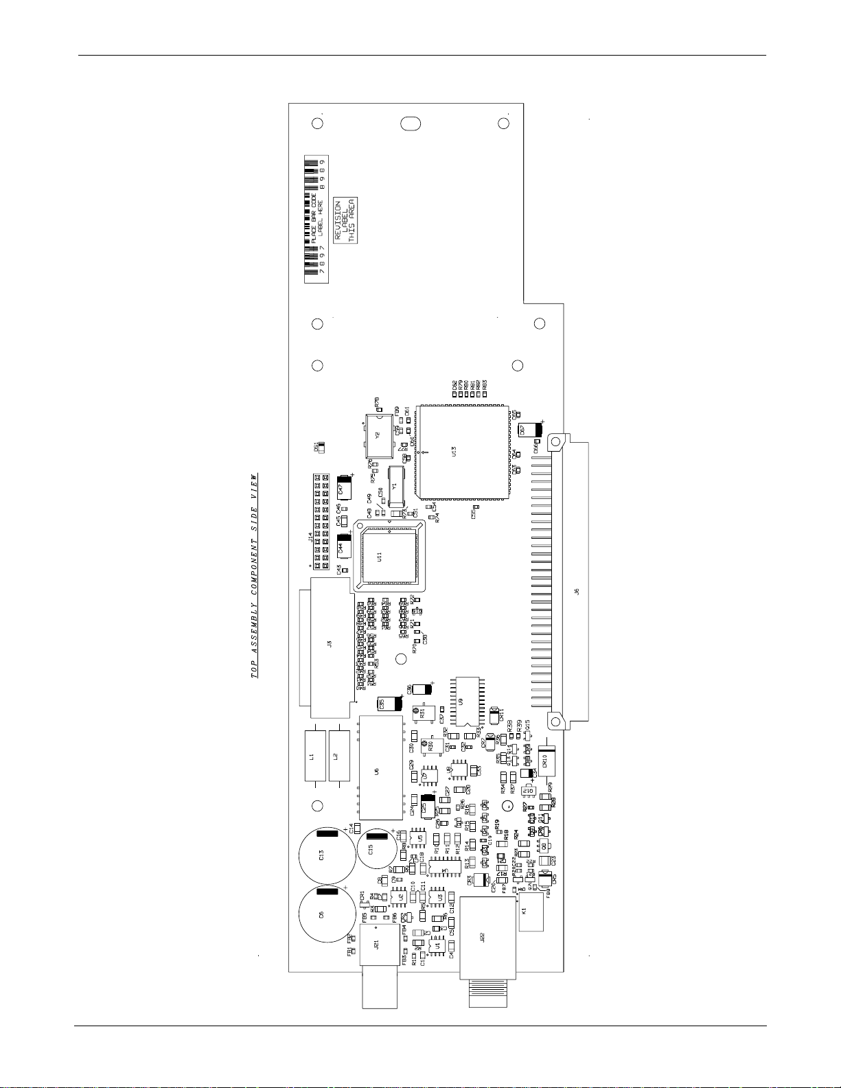
OPTION ASSEMBLIES AND PCBs: Parts Location Diagram PN 800836-002A
Parts Location Diagram PN 800836-002A
Revision A
Eagle 3000 Patient Monitor
415397-038
4-17
Page 99
OPTION ASSEMBLIES AND PCBs: Parts List PN 800836-002A
Parts List PN 800836-002A
Reference
Designation
C1, 7 Cap, Cer, 2200pF, 5%, 50V, SM 1182-222 2
C2, 4, 8, 10, 11, 12,
14, 16, 18, 20, 24, 28,
29, 30, 33, 45
C3, 26 Cap, Cer, 0.0056uF, 5% 1182-562 2
C5, 27 Cap, Cer, 0.0027
C6, 13 Cap, Al, 1500
C9, 17, 31, 32, 50, 51 Cap, NPO, 33pF, 5%, 50V, SM 411576-004 1
C15 Cap, Al, 820
C19, 49, 59 Cap, Cer, 0.1
C21 Cap, Cer, 0.047
C22, 37, 38, 43, 46,
48, 54, 55, 58, 60-66
C23 Cap, Cer, 0.22
C25, 35, 44, 47, 67 Cap, Tant, 10
C34 Cap, Tant, 1.0
C36 Serial Communication Controller, CMOS 85C30 401004-001 1
CR1, 2, 4 Diode Pair, Series, SM D7000 2013-201 3
CR3 Transorb, Bidirectional, 30V, 600W, SM SMBJ30 409052-001 1
CR5 Diode, Transient Voltage Suppression, SM
CR6, 8, 9 Diode, Schottky, SM BAT54 401985-001 3
CR7, 11 Diode, Schottky, Barrier, 1A, 40V, SM MBRS140T3 403187-001 2
CR10 Transient Voltage Suppressor, 16V, 10% 1N6276 410936-001 1
DS1 Light-Emitting Diode, Green, SM 1206 414417-004 1
FB1-9 Ferrite Bead BLM11A20 414061-001 9
J6 Connector, Dual In-Line, 96-Pin 410538-001 1
J14 Connector, Vertical, 12-Pin 1847-024 1
J21 Connector, Receptacle, PC Edge, 6-Pin 403933-001 1
J22 Jack, Phone, 1/4-inch, Right Angle, PCB 415158-001 1
J23 Connector, 50-Pin 404289-001 1
K1 Relay, SPDT, 5V, 280mW 409019-001 1
L1, 2 Inductor, Power, 33
Q1 Transistor, MOS-FET, N-Channel, SM 2N7002 401414-001 1
Q2, 3, 4, 5, 6, 9, 10,
11, 13, 14
Q7 Transistor, NPN, SM MMBT4401 405692-001 1
Q8, 12 Transistor, NPN, SM BCX56-1 2712-056 2
Q15, 16 Transistor, PNP, SM T3906 2511-101 2
R1, 4, 26, 27, 38, 39,
53, 61-72, 74, 75, 7883
Cap, Cer, 0.1
Cap, Cer, 0.1
P6SMB20AT1
Transistor, NPN, SM T3904 2511-001 10
Res, Cer, 10K, 1%, 1/16W, SM 410334-013 27
µ
µ
µ
µ
Description Part Number Qty
F, 20%, 50V 404370-001 16
µ
F, 5%, 50V, SM 1181-272 2
µ
F, 20%, 25V 414853-001 1
F, 20%, 25V, Radial 408957-001 1
F, 5%, 50V, SM 411575-012 3
µ
F, 5%, 50V, SM 1182-824 1
F, 5%, 16V 411575-002 16
µ
F, 5%, 50V, SM 1182-224 1
µ
F, 20%, 25V, SM 1152-106 5
µ
F, 10%, 35V, SM 403907-001 1
403939-001 1
µ
H, 1.81A, 10% 414943-001 1
4-18
Eagle 3000 Patient Monitor
415397-038
Revision A
Page 100
OPTION ASSEMBLIES AND PCBs: Parts List PN 800836-002A
Reference
Designation
R2, 3 Res, Cer, 100
Ω
Description Part Number Qty
, 1%, 1/8W, SM 1082-755 2
R5, 6, 11, 25 Res, Cer, 340K, 1%, 1/8W, SM 1082-782 4
R7, 8, 9, 10, 14 Res, Cer, 20K, 1%, 1/8W, SM 1082-202 5
R12, 34, 35, 36, 37 Res, Cer, 47.5K, 1%, 1/8W, SM 1082-757 5
R13 Res, Cer, 51.1K, 10%, 1/4W, SM 1082-772 1
R15 Res, Cer, 34.8K, 10%, 1/4W, SM 1082-791 1
R16, 28 Res, Cer, 3.4K, 1%, 1/8W, SM 1082-759 2
R17, 18 Res, Cer, 10K, 1%, 1/8W, SM 1082-104 2
R19 Res, Cer, 249
R20, 40-52, 54-60, 77 Res, Cer, 49.9
Ω
, 1%, 1/16W 410334-084 1
Ω
, 1%, 1/16W, SM 410334-040 22
R21, 22, 76 Res, Cer, 1K, 1%, 1/16W, SM 410334-008 3
R23, 29, 32, 33 Res, Cer, 49.9
Ω
, 1%, 1/8W, SM 1082-799 4
R24 Res, Cer, 1.5K, 1%, 1/8W, SM 1082-768 1
R30 Res, Var, 10K, SM 407457-004 1
R31 Res, Var, 100
Ω
, SM 407457-003 1
R73 Res, Chip, 4.7M, 1%, 1/8W, SM 1082-964 1
U1, 2, 3, 5, 8 Operational Ampl, JFET, Dual, SM MC34182D 401292-001 5
U4 Res, Ntwk, 20K, 0.1% 414854-001 1
U6 Converter, DC-DC, Isolated, 12V 414845-001 1
U7 Voltage Reference, SM LT1021DCS8-10 401294-001 1
U9 DAC, 12-Bit, Quad, PLCC DAC8221FS 406512-001 1
U11 Microprocessor, Writer 415259-002 1
U13 EPLD, Programmed, Eagle 3000 Option PCB 415295-003 1
Y1 Crystal, 3.6864MHz 408828-001 1
Y2 Crystal Oscillator, 25.000mHz, SM 405676-001 1
Socket, PLCC, 44-Pin, SM (for U11) 402412-001 1
Circuit Board 800837-002 1
Schematic Diagram SD800836-002 1
Revision A
Eagle 3000 Patient Monitor
415397-038
4-19
 Loading...