

Page 1

Page 2

02
WARNING
PACK CONTENTS
TECHNICAL SPECIFICATIONS
ELECTRICAL REQUIREMENTS
WIRING DIAGRAM
INSTALLATION OPTIONS
INTERNAL COMPONENTS
SAFETY
SITE REQUIREMENTS
CONNECTING TO SERVICES
HOW TO USE - HOW IT WORKS
TEMPERATURE CONTROL
ENERGY SAVING TIPS
FAULT FINDING (Troubleshooting)
SPECIAL EQUIPMENT AND ADVICE TO USERS
TEMPERATURE INCREASE CHART PER GPM
SPARE PARTS
CUSTOMER SERVICE
OTHER PRODUCTS
05
05
05
05
07
07
08
08
09
09
11
12
12
13
14
14
15
16
17
03
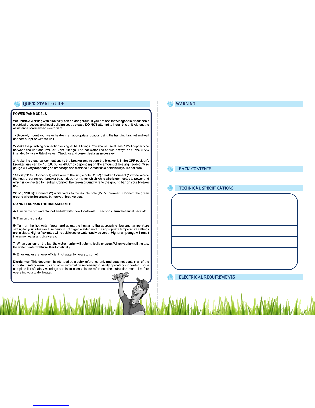
Congratulations!
You've just purchased a new Power Pak Plus tankless water heater and will
soon begin to enjoy the benefits of “going tankless.”
Please take the time to thoroughly read and understand this safety and
installation manual in its entirety before you attempt to install your new
tankless water heater, as it contains important safety tips and instructions.
Please carefully read all instructions and warnings. Should you have any
questions, please visit www.marey.com for installation videos and FAQ.
Please keep this manual for future reference and technical information.
QUICK START GUIDE 04
Page 3
If your water heater requires a reset, be sure to TURN OFF THE BREAKERS prior to resetting
the unit.
Resetting your unit without turning off the breakers can result in personal injury and damage
to your water heater.
WARNING! There is water contained in the coils of your water heater at all times. If your water
heater is exposed to freezing temperatures, the water in the coils could freeze, causing a
break in the heat exchanger of the unit, or the supply and return lines. This kind of damage will
result in water running freely into the space where the water heater is located, which can
cause flooding. DO NOT install this water heater where it may be subjected to a freeze. If your
water heater is in an area where freezing is a possibility, you must turn off the water to the
heater and drain it of any water by disconnecting the water lines. Leave the water lines
disconnected until you intend to use the water heater.
- Heater
- Hanging Bracket with Screws
The heater must be connected to its own independent electrical circuit. Install a
fuse box or switch (“breaker") for exclusive use of the heater.
PP110 PPXE5ITEM CODE
Voltage
Power
Inlet Pipe Measures
Outlet Pipe Measures
Amps.
Cycle
Water Pressure
Wires
Max. Gallons per Minute
Master Place Cover
Width x Height x Depth
Standard and Approvals
½" NPT
½" NPT
10-40A
50-60Hz
0.55 Bar (8 PSI) - 6.37 Bar (92.365 PSI)
8 AWG
2 GPM 3 GPM
ABS Heating Elements Copper
11.1" x 10.2" x 4.8"
ISO 9001
110V
1.1kW - 4.4kW
220V
2.2kW - 8.8kW
04 05
Page 4

The wire gauge necessary will vary based on amperage and distance to the breaker,
but 8 gauge wire is generally sufficient for most installations. If the distance is very
short, sometimes smaller gauge wire may be used. If you aren't sure which gauge of
wire should be used, contact an electrician. The supply wire, main switch and
circuit protection (Leakage Circuit Breaker) must be sufficient for the
amperage required. Please check the table above and the flow rate/temperature
rise chart for the appropriate amperage for your situation. Note that the lower the
amperage, the lower the water temperature rise will be.
DO NOT TURN ON THE BREAKER SWITCH UNTIL ALL ELECTRICAL AND
PLUMBING CONNECTIONS ARE MADE AND WATER IS FLOWING THROUGH
THE UNIT.
Connect (1) white wire to the single pole 10, 20, 30 or 40 Amp circuit breaker.
Connect (1) white wire to the neutral bar on your breaker box. It does not matter
which white wire connects to neutral and which connects to the breaker. Connect
the green ground wire to the ground bar on your breaker box.
Connect the (2) white wires to the double pole 10, 20, 30 or 40 Amp circuit breaker.
Connect the green ground wire to the ground bar on your breaker box.
This appliance MUST be grounded. Connect the ground wire, as indicated in the
Electrical Code.
When all connections are satisfactorily prepared, install the heater cover. With the
insulated container off and water flow modifier (optional) fully open, the faucet must
be opened fully to get maximum water flow . It is necessary to ensure that the water
tank is full before turning the power on. This is an essential step to protect the
heating element.
Note that the above instructions are simply guidelines that apply to most
installations.
The size of the switch and wire gauge must meet all local, state, provincial and
national electrical codes in your area. Contact an electrician if you're not sure.
To determine the minimum electrical circuit please see the next table:
For PP110:
For PP220 (PPXE5):
Remember that the above instructions are just guidelines that apply at most
installations.
Remember that you should remove the red and blue covers before installing your
unit.
Swing Check Valve
Main Water Supply Valve
Green Ground Wire.
Connect to ground bar on breaker box.
POWER PAK - PLUS
Amperage Control Knob
PP110: Connect (1) white wire to
breaker and (1) white wire to neutral.
PP220: Connect both white wires to
breaker.
ONE POINT OF USE TWO OR MORE POINTS OF USE
Power Selector
Minimum Breaker
Position 1 and 2
Position 1, 2 and 3
Position 1, 2, 3 and 4
20 Amperes
30 Amperes
40 Amperes
06 07
Page 5

08 09
Working with electricity requires proper skills and knowledge – Installation of the unit
should be performed by someone who is familiar or trained in this trade. We HIGHLY
recommend that you hire the services of a licensed and qualified
“Electrician/Plumber” familiar with tankless water heaters installation.
IMPROPER INSTALLATION CAN CAUSE INJURY OR EVEN DEATH.
IMPORTANT: All electrical work and unit fixing to the wall should be completed
before connecting electrical wiring.
When you turn on the unit, extremely hot water could come out. Take proper safety
precautions to avoid being hurt or burned by water.
DO NOT expose the unit to freezing temperatures. Do not use an input water
temperature over 90 degrees F or 32.2 degrees Celsius. This unit is designed for
indoor use only.
DO NOT restrict the flow of water entering the unit.
DO NOT operate the appliance if water ceases to flow during use, if the outer case or
cover is loose or if the unit is not working properly.
If the unit leaks or does not heat properly, disconnect the unit.
ISOLATE the electrical and water supplies before removing the cover and before
proceeding with installation or servicing.
NEVER OPERATE THIS HEATER WITHOUT THE COVER!
WATER AND PLUMBING REQUIREMENTS
DO NOT USE PVC, CPVC or plastic supply lines directly to the unit. A16” copper or
stainless steel pipe must be connected to the heater and then adapted to a different
material such as (CPVC, PVC or PEX PLASTIC).
Be sure to clean the pipes before connecting the heater to the main line. Clean all
the impurities of the pipe, allowing water to flow for a few minutes, check for leaks.
Any residue or dirt in the pipes may cause internal damage to the unit.
Connect the isolation valve at the entry inlet pipe of the heater and make sure you
install a rubber washer. Do not apply excessive force to tighten connectors. A safety
release valve must be fitted in the supply pipe.
We recommend installing a sediment filter before the entry of water to the heater.
Hard water or water with high levels of minerals and alkali can cause damage to this
unit. When this is the case, we recommend the use of a (non-salt) water softening
system.
The provision of a service stop valve in the cold supply pipe will assist in the event of
any subsequent servicing or maintenance.
These heaters are of the closed type (closed system with no ventilation pressure)
suitable for fitting to the normal input of cold water with a maximum of 94 PSI (6.5
bar). They must be fitted with a pressure valve adjacent to the entrance.
PREPARATION
1. Isolate electrical and water supplies BEFORE proceeding with the installation.
Page 6

10 11
ON
OFF
ON
OFF
VERTICAL POSITION
PIPES FACING
DOWN
2. The unit must be mounted on a flat surface in a vertical position with the incoming
and outgoing water pipes facing down. It is not possible to install the unit
horizontally. Please use the installation sticker guide and screws supplied in the
product's original package. Drill the wall for the indicated holes. Check that there are
no hidden wires or pipes, before drilling holes for wall mounting.
3. Secure the bracket to the wall with the screws supplied.
4. Hook the unit and screw the fixing holes, placing special attention to the bottom
screw.
CABLE ENTRY
5. There are two cable entry points. You can choose one of them and the back plate
will have to be cut out.
6. This appliance MUSTbe grounded.
ON
OFFONOFF
WATER INLET
RIGHT SIDE
WATER OUTLET
LEFT SIDE
OUTLET
INLET
PLUMBING
7. Use stainless steel flexible hose or copper tubing of ½" on the inlet and outlet
pipes (right side water inlet, hot water outlet, left).
8. Turn on the mains water supply to the water heater and then plug the unit at the
isolated electrical outlet.
NOTE: The electrical supply is not turned on until all the pipes and the installation is
complete.
THE WATER HEATER WILLTURN ON, WHEN YOU:
1. Turn on a water faucet.
2. The power indicator will light.
TO STOPTHE WATER HEATER:
Turn off the faucet.
TO USE THE POWER SELECTOR:
The power selector knob has five positions:
Page 7

The water temperature is altered by increasing or decreasing the flow rate of the
water through the water heater, via the temperature control knob. Increased
amperage settings will result in increased water temperature.
NOTE: If water pressure is low, the inlet pipe of the water should be ¾ "with outputs
of 5/8".
The heater should be installed as close as possible to the point of use to avoid heat
loss. If longer distances are required, hot water pipes should be insulated.
Adjust heater temperature settings (located on the front panel of the heater) to the
desired output temperature. Lowering the power setting will save energy, but hot
water temperature will decrease.
12
13
Power
Selector
Water
Temperature
Off
I (10A)
II (20A)
III (30A)
IIII (40A)
Cold
Temperate
Hot
Hotter
Max. Hot Water
Temperature
Small Drop:
Lower water outflow.
Warmer water.
Big Drop:
Higher water outflow.
Less hot water.
We recommend that you install the unit under the sink in the main bathrooms or
utility areas. This will allow for lower amperage usage and a reduced heat loss from
long pipe runs.
For additional savings, reduce the water flow valve at the inlet of the heater so the
temperature increases.
Your Marey Power Pak Plus should give you trouble free operation, however should
a problem or fault occur, the table below will assist in identifying the most common
faults. Diagnosis and fault finding should be carried out by a qualified individual,
skilled in electrical/plumbing.
Power not connected
No heating occurs
Insufficient Amperage
at Breaker
Too much water flow
Too little water flow
Heating Dial Not High
Enough
Incorrect Wiring
Overheat Sensor
Engaging
Water is not warm
enough
Water starts out
hot but then unit
shuts off
Breaker is tripping
Double check for correct
wiring and that all
connections are secure.
Ensure that there is
sufficient water flow to
engage unit (9 PSI)
Increase size of breaker
to 40 Amps if smaller
breaker is in use. Turn
heating dial to full.
Reduce amount of water
flowing through the unit.
Oveheat sensor is
shutting the unit off.
Increase water flow or
decrease heat setting.
Double check for correct
wiring and that all
connections are secure.
Ensure that heating dial
is no higher than breaker
size.
Page 8

14 15
1 2 3 4PP110
GPM*
0.75
1.0
1.25
1.5
2.0
11º
8º
6º
5º
3º
25º
18º
14º
12º
7º
36º
30º
23º
20º
11º
38º
32º
30º
26º
16º
TEMP. INCREASE PER GPM
*GPM = Gallons per Minute
1 2 3 4
GPM*
1.0
1.5
2.0
2.5
3.0
25º
17º
12º
10º
46º
32º
21º
17º
66º
48º
31º
25º
20º
58º
41º
33º
26º
13º6º
TEMP. INCREASE PER GPM
The pressure relief device is designed into the water heater. The device will work
automatically, when excessive build up of pressure occurs. Do not replace the
pressure relief device with any other screw.
The unit is built of fireproof material.
There is a safety thermal cut-out device in the water heater. This thermostat will cut
off electricity to prevent scalding, when there is a sudden rise in water temperature,
this protecting the user.
All models can be fitted with Leakage Circuit Breaker. (optional)
It is important to keep the showerhead clean in order to maintain the performance of
the water heater.
*Temperature increases listed are based on use of the water heater under optimal
conditions with an incoming water temperature of 48ºF. Variable factors such as
incorrect or imperfect installation or warmer incoming water temperature may yield
different results.
The following comprehensive list of spare parts is available for your Power Pak Plus.
DO NOT REPLACE WITH PARTS NOT RECOMMENDED BY MAREY, AS THIS
WILLINVALIDATE YOUR WARRANTY AND MAYRENDER THE INSTALLATION
DANGEROUS.
Description:
- Thermostat
- Safesty Valve
- Heating Element Container
- Microswitch
- Water Valve
*Reference in
page 8
Page 9

16 17
1-855-MAREY-55
customerservice@marey.com
Delbrey Street, 211
San Juan, Puerto Rico
00912
Tel: 1-512-332-2229
Toll Free: 1-855-627-3955
1-855-MAREY-55
www.marey.com
At Marey, we pride ourselves on the excellence of our customer service and support
team.
Please feel free to contact us if you have any questions about our products, warranty
service, or if you need assistance installing a unit. We also strive for continuous
improvement, so we welcome your comments, feedback and s uggestions.
Marey proudly manufactures water heaters and accessories for use in almost
any application. Please visit our website to learn more about other Marey
products.
AQUAMATIC ECO180 SANTON
POWERPAK PORTABLE POWER GAS
 Loading...