

Maretron TLM100 User Manual

®®
TLM100
Tank Level Monitor
User’s Manual
Revision 1.3
Copyright © 2010 Maretron, LLP All Rights Reserved
Maretron, LLP
9014 N. 23
Phoenix, AZ 85021
http://www.maretron.com
Maretron Manual Part #: M002201
rd
Ave #10
Revision 1.3 Page i
TLM100 User’s Manual
Revision History
Revision Description
1.0 Original document
1.1 Corrected typo in NMEA protocol PGN list
1.2 Typographical corrections
1.3 Added documentation on mounting locations and theory of operation
Corrected torque specifications
Added prohibition of red Loctite threadlocking compound and cleaning agents
containing acetone
Updated troubleshooting section
Updated referenced firmware version number
Typographical corrections
Page ii Revision 1.3

®®
Table of Contents
1 General ................................................................................................................................ 1
1.1 Introduction .................................................................................................................... 1
1.2 Gasoline Tanks .............................................................................................................. 1
1.3 Firmware Revision ......................................................................................................... 1
1.4 Features ........................................................................................................................ 1
1.5 TLM100 Accessories ..................................................................................................... 2
1.6 Quick Install ................................................................................................................... 2
2 Installation ............................................................................................................................ 2
2.1 Unpacking the Box ......................................................................................................... 2
2.2 Theory of Operation ....................................................................................................... 2
2.3 Choosing a Mounting Location ...................................................................................... 3
2.3.1 Effect of Pitch and Roll on the TLM100 ............................................................... 4
2.3.2 Use of an Airlock on Black Water Tanks ............................................................. 4
2.4 Mounting the TLM100 .................................................................................................... 5
2.4.1 Mounting the TLM100 Sensor Component ......................................................... 5
2.4.2 Mounting the TLM100 Interface Component ....................................................... 9
2.5 Connecting the TLM100 .............................................................................................. 10
2.5.1 Connecting to NMEA 2000® Interface ............................................................... 10
3 Configuring the TLM100 ..................................................................................................... 11
3.1 Configuring Tank Type ................................................................................................ 11
3.2 Configuring Tank Number ............................................................................................ 11
3.3 Configuring Tank Capacity .......................................................................................... 11
3.4 Tank Depth or Custom Calibration ............................................................................... 12
3.4.1 Tank Depth Programming ................................................................................. 12
3.4.2 Custom Calibration............................................................................................ 12
4 Maintenance ....................................................................................................................... 12
5 Troubleshooting ................................................................................................................. 12
6 Technical Specifications ..................................................................................................... 14
7 Technical Support .............................................................................................................. 15
8 Maretron (2 Year) Limited Warranty ................................................................................... 16
Revision 1.3 Page iii

TLM100 User’s Manual
Table of Figures
Figure 1 - TLM100 Operation .................................................................................................... 3
Figure 2 – TLM100 Mounting – SAE 5-Hole Bolt Pattern .......................................................... 6
Figure 3 – Mounting TLM100 to SAE 5-Hole Tank with Focus Tube ......................................... 7
Figure 4 – TLM100 Mounting With Threaded Adapter ............................................................... 8
Figure 5 – Mounting TLM100 with Focus Tube on Threaded Tank Fitting................................. 9
Figure 6 – TLM100 Connections ............................................................................................. 10
Figure 7 – NMEA 2000® Connector Face Views ..................................................................... 10
Figure 8 – Troubleshooting Guide ........................................................................................... 13
Table of Appendices
Appendix A – NMEA 2000® Interfacing .................................................................................... A1
Page iv Revision 1.3

®®
1 General
1.1 Introduction
Congratulations on your purchase of the Maretron Tank Level Monitor (TLM100). Maretron has
designed and built your monitor to the highest standards for years of reliable, dependable, and
accurate service.
The TLM100 is used to sense levels of liquid tanks using ultrasonic technology and transmit
the liquid levels over the NMEA 2000® network. This allows you to observe tank levels
anywhere on the vessel where there is an NMEA 2000® compatible display such as the
Maretron DSM250. The TLM100 is capable of sensing tanks up to 40” (1.02m) in depth. It can
be used for diesel, fresh water, grey water, black water, and oil tanks. Unlike most tank
senders that only work with rectangular tanks, the TLM100 can be calibrated for irregular tank
shapes so you know the true level of your tanks. The TLM100 can be mounted on tanks with a
SAE J1810 5-hole mounting pattern, or to tanks using 1.5” NPT or 1.25” BSP threaded
openings via available adapters. The TLM100 has an optional airlock for black water
applications to keep the face of the ultrasonic transmitter from fouling, and an optional focus
tube to allow use on boats with planing hulls when the vessel spends a significant amount of
time with the bow pitched up.
The Maretron TLM100 is designed to operate within the harsh demands of the marine
environment. However, no piece of marine electronic equipment can function properly unless
installed, calibrated, and maintained in the correct manner. Please read carefully and follow
these instructions for installation, calibration, and usage of the Maretron TLM100 in order to
ensure optimal performance.
1.2 Gasoline Tanks
The TLM100 is NOT intended for use in tanks containing gasoline. Use in tanks containing
gasoline will void the product warranty. For gasoline tank applications, please use the
Maretron TLM100 Gasoline Tank Level Monitor.
1.3 Firmware Revision
This manual corresponds to TLM100 firmware revision 1.1.5.
1.4 Features
The Maretron TLM100 has the following features:
• Transmits liquid levels over an NMEA 2000® Interface
• Integrated ultrasonic level sensor
• Can be used in tanks up to 40” (1.02m) deep
• SAE J1810 5-hole, 1.5” NPT, or 1.25” BSP Mounting
• Accommodates Irregularly Shaped Tanks with 16 Point Calibration
• 16 Programmable Tank Types Including Fuel, Fresh Water, Waste Water, Live Well
• Programmable Tank Number(s) Up to 16 per Tank Type
• Programmable Tank Capacity
Revision 1.3 Page 1

TLM100 User’s Manual
1.5 TLM100 Accessories
Maretron offers the following accessories for the TLM100:
• TA-5H-1.5NPT 1.5” NPT Displacement Hull Tank Adapter
• TA-5H-1.25BSP 1.25” BSP Displacement Hull Tank Adapter
• TFT-5H SAE 5-Bolt Pattern Non-Displacement Hull Focus Tube
• TFT-1.5NPT 1.5” NPT Non-Displacement Hull Focus Tube
• TFT-1.25BSP 1.25” BSP Non-Displacement Hull Focus Tube
• TAL-5H SAE 5-Bolt Pattern Black Water Airlock
• TAL-1.5NPT 1.5” NPT Black Water Airlock
• TAL-1.25BSP 1.25” BSP Black Water Airlock
1.6 Quick Install
Installing the Maretron TLM100 involves the following steps. Please refer to the individual
sections for additional details.
1. Unpack the Box (Section 2.1)
2. Choose a Mounting Location (Section 2.3)
3. Mount the TLM100 (Section 2.4)
4. Connect the TLM100 (Section 2.5)
5. Configure or Program the Tank Type (Section 3.1)
6. Configure or Program the Tank Number (Section 3.2)
7. Configure or Program Tank Capacity (Section 3.3)
8. Configure for Tank Depth and Shape
o Configure or Program the Tank Depth (Section 3.4.1)
o Custom Calibration (Section 3.4.2)
2 Installation
2.1 Unpacking the Box
When unpacking the box containing the Maretron TLM100, you should find the following items:
• 1 – TLM100 Tank Level Monitor
• 1 – TLM100 Gasket
• 1 – TLM100 User’s Manual
• 1 – Warranty Registration Card
If any of these items are missing or damaged, please contact Maretron.
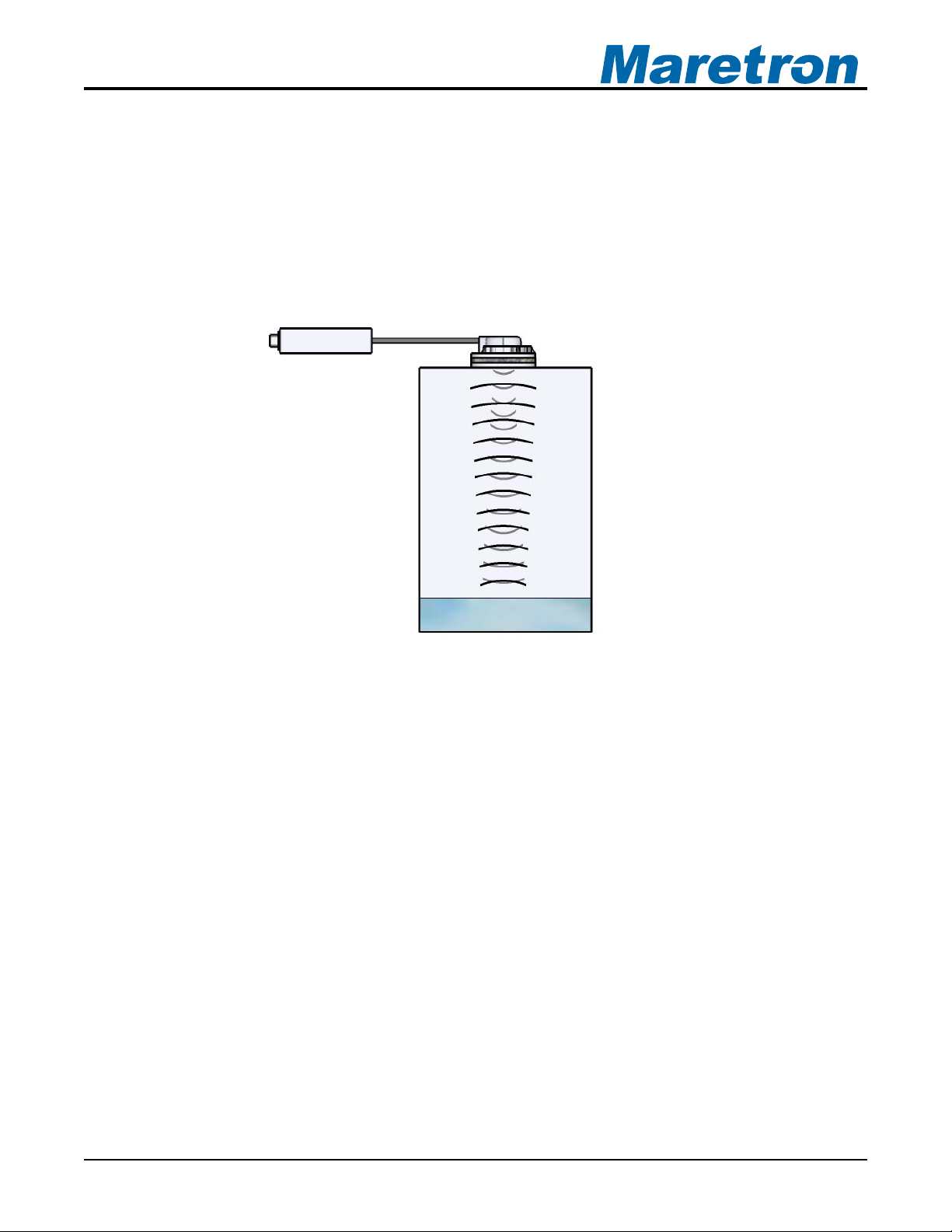
2.2 Theory of Operation
The TLM100 operates by directing a pulse of ultrasonic sound from the sensor component at
the top of the tank down to the surface of the liquid in the tank. The TLM100 then measures
the time it takes this pulse to travel down to the surface of the liquid, be reflected back up, and
Page 2 Revision 1.3
®®
then be received back at the sensor component. Using the speed of sound, it uses this time to
calculate the distance between the face of the sensor component and the surface of the liquid
(or the tank bottom if the tank is empty). The cone width of the beam transmitted by the
TLM100 sensor component is 6°. Please refer to Figure 1 below for a diagram of the waves
emitted and received by the TLM100.
Please note that due to limitations of ultrasonic technology, the minimum depth that can be
measured by the TLM100 is 2” (5.08cm).
Figure 1 - TLM100 Operation
2.3 Choosing a Mounting Location
The primary function of the TLM100 is to sense levels of liquid in tanks using ultrasonic
technology and transmit this information over NMEA 2000
information can be viewed anywhere on the vessel where there is an NMEA 2000® compatible
display.
The TLM100 tank level monitor consists of two parts: 1) the sensor, which mounts onto the top
of the tank and contains the ultrasonic level measurement components, and 2) the interface,
which converts the measured data into NMEA 2000® format and transmits the data over the
NMEA 2000
The interface component of the TLM100 may be mounted anywhere, subject to the length of
the cable connecting it to the sensor component.
The sensor component of the TLM100 must be mounted on the tank whose level is to be
monitored. Choosing a proper mounting location for the sensor component of the TLM100 is
critical to obtaining accurate tank level readings. For best results, please follow these
recommendations:
®
network.
• The sensor component of the TLM100 must be mounted flat, so that the round
transceiver portion of the TLM100 faces straight downward.
®
network so that tank level
Revision 1.3 Page 3
 Loading...