

Maretron SSC200 User Manual

®®
SSC200
Solid State Rate/Gyro Compass
User’s Manual
Revision 1.8
Copyright © 2012 Maretron, LLP All Rights Reserved
Maretron, LLP
9014 N. 23
Phoenix, AZ 85021-7850
http://www.maretron.com
Maretron Manual Part #: M000401
rd
Ave #10
Revision 1.8 Page i

SSC200 User’s Manual
Revision History
Revision Description
1.0 Original document.
1.1 Minor editorial changes.
Corrected default rate for Rate of Turn PGN under Technical Specifications.
1.2 Minor editorial changes.
Removed Warranty Card.
1.3 Changed copyright to 2005.
Added text to describe new feature (programmable variation) under Section 1.2,
3.0, 3.3, and Appendix B.
1.4 Added Variation section.
Added Rate of Turn section.
Updated Appendix A Maretron Proprietary Execute Sentence definitions.
Updated Appendix A Maretron Proprietary Set Period sentence table.
Added programming examples to Appendix A Maretron Proprietary Set Period
for enabling, disabling, and changing frequency of transmission of different
NMEA 0183 sentences.
Added Calibration Warning
1.5 Added Firmware Revision section indicating firmware revision 1.9
Added note to Appendix A that checksums are optional and removed checksums
from received sentences.
Added deviation compass environment quality measurements report from
compass.
Added rate of turn zeroing section.
1.6 Updated Supported Firmware Revision to 2.0.
Incorporated instructions on interfacing directly to a PC as Appendix C
Incorporated Magnetic Variation App Note (AN2) as Appendix D
Incorporated HDT App Note (AN1) as Appendix E
Added support for 38400 baud rate for P/N M000021 compasses.
1.7 Updated Section 3.1.2 describing compass output after successful deviation.
Updated installation to include power connections through NMEA 2000 port
Updated installation – SSC200 can be installed upside down and/or backward
1.8 Corrected order of parameters in $PMAREXE,ATT sentence description
Added cautions about using red Loctite and acetone cleaners
Updated “Unpacking the Box” items list
Added Appendix F on changing the NMEA0183 identifier
Clarified usage of PMARSETPX vs. PMARSETP sentences
Added NMEA0183 sentence to cause SSC200 to retransmit last calibration
status message
Editorial note in NMEA 0183 connections about consulting manufacturer of
connected products for connection information
Added length of NMEA 0183 cable (10m)
Page ii Revision 1.8

®®
Table of Contents
1 General .............................................................................................................................. 1
1.1 Introduction ................................................................................................................ 1
1.2 Firmware Revision ..................................................................................................... 1
1.3 Features .................................................................................................................... 1
1.4 Quick Install ............................................................................................................... 1
2 Installation .......................................................................................................................... 2
2.1 Unpacking the Box .................................................................................................... 2
2.2 Choosing a Mounting Location .................................................................................. 2
2.3 Mounting the SSC200 ............................................................................................... 3
2.3.1Mounting the SSC200 to a Horizontal Surface ........................................... 3
2.3.2Mounting the SSC200 to a Vertical Surface ............................................... 4
2.4 Connecting the SSC200 ............................................................................................ 5
2.4.1Connecting to NMEA 2000® Interface ........................................................ 6
2.4.2Connecting to NMEA 0183 Interface .......................................................... 7
If the NMEA 2000® interface is connected, power is supplied to the SSC200
through the NMEA 2000® network connection. ................................................... 8
2.4.3Connecting Both NMEA 2000® and NMEA 0183 Interfaces ..................... 10
2.4.4Checking Connections .............................................................................. 10
3 Calibration ........................................................................................................................ 10
3.1 Magnetic Deviation Calibration ................................................................................ 10
3.1.1Maretron Display Initiated Deviation Calibration ....................................... 11
3.1.2Automatic Power-Up Deviation Calibration ............................................... 11
3.2 Installation-Offset Correction ................................................................................... 12
3.2.1Maretron Display Product Offset Correction ............................................. 12
3.2.2Manual Installation-Offset Correction ....................................................... 12
4 Variation ........................................................................................................................... 13
4.1 Variation Input via NMEA 0183 Interface ................................................................. 13
4.2 Variation Input via the NMEA 2000® Interface ......................................................... 14
4.3 Variation Input via Manual Entry .............................................................................. 14
4.4 Variation Source Selection ...................................................................................... 15
4.4.1Variation Source Selection via Maretron Display ...................................... 15
4.4.2Variation Source Selection via NMEA 0183 Interface ............................... 15
5 Rate of Turn ..................................................................................................................... 15
5.1 Rate of Turn Damping Period Selection with Maretron Display ............................... 16
5.2 Rate of Turn Damping Period Selection by NMEA 0183 Interface .......................... 16
5.3 Rate of Turn Zeroing ............................................................................................... 16
6 Maintenance .................................................................................................................... 16
7 Troubleshooting ............................................................................................................... 17
8 Technical Specifications ................................................................................................... 18
9 Technical Support ............................................................................................................ 19
10 Installation Template ........................................................................................................ 20
11 Maretron (2 Year) Limited Warranty ................................................................................. 21
Revision 1.8 Page iii

SSC200 User’s Manual
Table of Figures
Figure 1 – Mounting the SSC200 to a Horizontal Surface ......................................................... 4
Figure 2 – Mounting the SSC200 to Vertical Surface ................................................................ 5
Figure 3 – NMEA 2000® / NMEA 0183 Interface Connector Locations ..................................... 6
Figure 4 – NMEA 2000®/Power Connector Face Views ............................................................ 6
Figure 5 - SSC200 with NMEA 2000® Connection Only ............................................................ 7
Figure 6 – NMEA 0183 Connector Face Views ......................................................................... 8
Figure 7 – NMEA 0183 Cable/Wire Color Coding ...................................................................... 8
Figure 8 - SSC200 with NMEA 0183 Connection Only .............................................................. 9
Figure 9 – Trouble Shooting Guide .......................................................................................... 17
Figure 10 – Horizontal Mounting Surface Template ................................................................ 20
Figure 11 – Vertical Mounting Surface Template ..................................................................... 20
Table of Appendices
Appendix A – NMEA 0183 Interfacing ..................................................................................... A1
Appendix B – NMEA 2000® Interfacing .................................................................................... B1
Appendix C – Connecting to a PC Via NMEA 0183 ................................................................. C1
Appendix D – Configuring the SSC200 to Transmit True Heading Data ................................. D1
Appendix E – Configuring the SSC200 to Transmit the HDT Sentence for …and Radars ...... E1
Page iv Revision 1.8

®®
1 General
1.1 Introduction
Congratulations on your purchase of the Maretron SSC200 Solid State Rate/Gyro Compass.
Maretron has designed and built your compass to the highest standards for years of reliable,
dependable, and accurate service.
The SSC200 detects the direction of the earth’s magnetic field using solid state
magnetometers and indicates the vessel heading relative to magnetic north. In addition, the
SSC200 incorporates solid state accelerometers and a solid state angular rate sensor for
indicating the vessel’s attitude (pitch and roll) and rate of turn.
The Maretron SSC200 is designed to operate within the harsh demands of the marine
environment. However, no piece of marine electronic equipment can function properly unless
installed, calibrated, and maintained in the correct manner. Please read carefully and follow
these instructions for installation, calibration, and usage of the Maretron SSC200 in order to
ensure optimal performance.
1.2 Firmware Revision
This manual corresponds to SSC200 firmware revision 2.0.
1.3 Features
The Maretron SSC200 Solid State Compass has the following features.
• NMEA 2000® and NMEA 0183 Interfaces
• Solid State Magnetometers for Indicating the Vessel’s Heading
• Solid State Accelerometers for Indicating the Vessel’s Attitude (Pitch and Roll)
• Solid State Angular Rate Sensor for Indicating the Vessel’s Rate of Turn
• Advanced Kalman Filtering for Stable and Accurate Output During Dynamic Conditions
• Fast Response Time Stabilizes Auto-Pilot Systems
• Calibration for Compensating Magnetic Deviation Caused by Hard and Soft Iron Effects
• Installation-Offset Capability for Aligning the Compass to the Vessel
• Programmable Variation
• Waterproof Enclosure and Cable System
1.4 Quick Install
Installing the Maretron SSC200 compass involves the following six steps. Please refer to the
individual sections for additional details.
1. Unpack the Box (Section 2.1)
2. Choose a Mounting Location (Section 2.2)
3. Mount the SSC200 Compass (Section 2.3)
4. Connect the SSC200 Compass (Section 2.4)
5. Calibrate the SSC200 Compass for Magnetic Deviation (Section 3.1)
Revision 1.8 Page 1

SSC200 User’s Manual
6. Calibrate the SSC200 Compass for Installation-Offset (Section 3.2)
7. Use Default Variation Source or Select an Appropriate Variation Source (Section 4)
2 Installation
2.1 Unpacking the Box
When unpacking the box containing the Maretron SSC200, you should find the following items.
• 1 - SSC200 Solid State Compass
• 2 - Mounting Brackets
• 4 - Mounting Bracket Screws
• 4 - Mounting Screws
• 1 - 10 meter NMEA 0183 Cable*
• 1 - NMEA 2000
• 1 - SSC200 User’s Manual
• 1 - Warranty Registration Card
* Only included in SSC200-01
If any of these items are missing or damaged, please contact Maretron.
®
Micro Field Attachable Connector (Female)*
2.2 Choosing a Mounting Location
The selection of a suitable mounting location is important for the optimal performance of the
Maretron SSC200. The mounting location and orientation of the Maretron SSC200 should be:
1. Level with the Earth’s Horizontal Plane – Although the SSC200 can be calibrated in the
vessel to compensate for pitch and roll installation-offset, it is best to mount the compass as
level as possible to maximize its pitch and roll operational range.
2. Oriented with Arrow Pointing to Bow Parallel to Vessel Centerline – Although the SSC200
can be calibrated in the vessel to compensate for heading installation-offset, it is best to
mount the compass pointed towards the bow and parallel to the vessel centerline. The
SSC200 can be mounted in other orientations, although this requires additional
configuration steps; please refer to Section 2.3 on page 3 for details.
3. Near the Center of Gravity (CG) of the Vessel – The compass experiences the least amount
of movement when located at the CG, which allows the most accurate readings. This is
similar to a traditional card/needle compass, where the farther the compass is from the CG,
then the more the fluid sloshes around, making accurate readings more difficult.
4. Away from Structures Containing Ferrous Metals – The earth’s lines of magnetic flux tend to
become distorted in the vicinity of ferrous metals, which can potentially cause errors in the
compass’s indicated heading. The SSC200 can be calibrated to compensate for these
errors, but it is still best to minimize the errors by placing the compass as far away from
ferrous metals as is practical.
5. Away from Magnetic Field Sources – Power or ignition cables, electric motors, and other
electronic equipment can create magnetic fields. The earth’s lines of magnetic flux tend to
become distorted in the vicinity of magnetic field sources, which can potentially cause errors
in the compass’s indicated heading. The magnetic fields tend to come and go as power is
Page 2 Revision 1.8

®®
switched on and off, which makes compensation impractical. Therefore, you should try to
mount the compass as far away as possible from these magnetic field sources (doubling the
distance between the magnetic field source and the compass will reduce the field strength
by a factor of approximately 8). Also, always observe any “compass-safe distance” markings
on other electronic equipment.
6. Minimal Vibration – Although the SSC200 is more tolerant of vibration than a fluxgate
compass, it is best to mount the compass in a location free of vibration as opposed to a
location with vibration.
2.3 Mounting the SSC200
The Maretron SSC200 compass can be mounted to a horizontal surface such as a floor or
deck (Section 2.3.1) or it can be mounted to a vertical surface such as a wall or bulkhead
(Section 2.3.2).
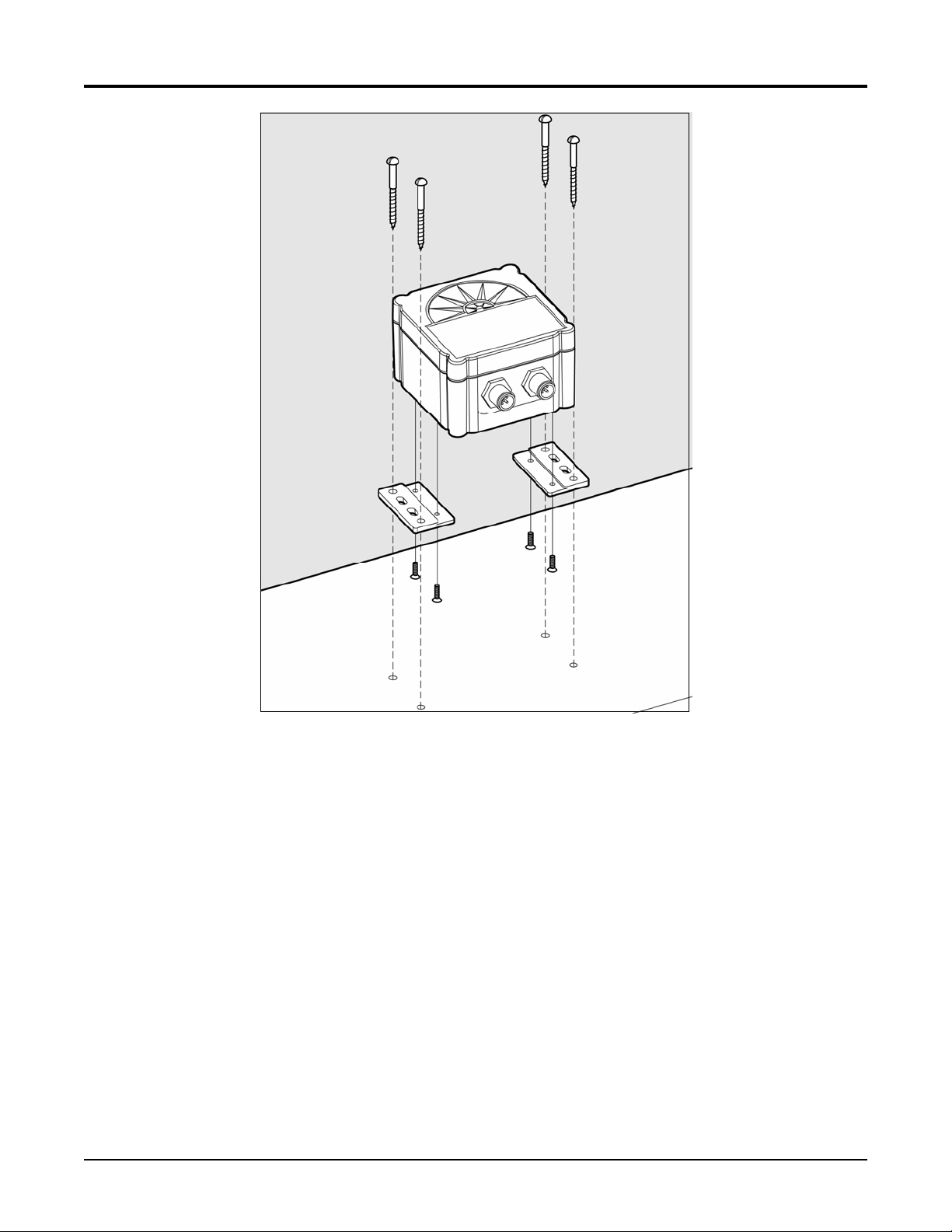
2.3.1 Mounting the SSC200 to a Horizontal Surface
Mounting the SSC200 compass to a horizontal surface requires that the provided mounting
brackets be fastened to the bottom of the SSC200 using the provided brass flat head screws.
Once the mounting brackets are securely fastened to the bottom of the SSC200, attach the
SSC200 securely to the vessel using the included brass mounting screws or other non-ferrous
fasteners as shown in Figure 1. Do not use threadlocking compounds containing methacrylate
ester, such as Loctite Red (271), as they will cause stress cracking of the plastic enclosure.
The usual way of mounting the SSC200 to a horizontal surface is to mount it to the top of the
horizontal surface; however, the SSC200 may be mounted upside down to the underside of a
horizontal surface, provided that the SSC200 is programmed to recognized that it is mounted
upside down. This can be done using a Maretron display product (e.g., DSM200 - please refer
to the DSM200 user’s manual for details).
Revision 1.8 Page 3
SSC200 User’s Manual
Figure 1 – Mounting the SSC200 to a Horizontal Surface
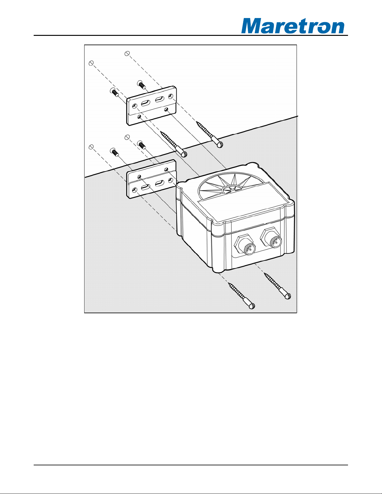
2.3.2 Mounting the SSC200 to a Vertical Surface
Mounting the SSC200 compass to a vertical surface requires that the provided mounting
brackets be fastened to the side of the SSC200 using the provided brass flat head screws.
Once the mounting brackets are securely fastened to the side of the SSC200, attach the
SSC200 securely to the vessel using the included brass mounting screws or other non-ferrous
fasteners as shown in Figure 2. Do not use threadlocking compounds containing methacrylate
ester, such as Loctite Red (271), as they will cause stress cracking of the plastic enclosure.
The usual way of mounting the SSC200 to a vertical surface is attaching the SSC200 to the
forward side of a vertical surface, so that the side of the compass with the connectors is facing
the bow of the boat; however, the SSC200 may be mounted to the astern side of a vertical
surface, so that the side of the compass with the connectors is facing the stern of the boat,
provided that the SSC200 is programmed to recognized that it is mounted in this way
(“backwards”). This can be done using a Maretron display product (e.g., DSM200 - please
refer to the DSM200 user’s manual for details).
Page 4 Revision 1.8
®®
Figure 2 – Mounting the SSC200 to Vertical Surface
2.4 Connecting the SSC200
You have a choice of connecting the SSC200 to a NMEA 2000® interface (Section 2.4.1),
NMEA 0183 interface (Section 2.4.2), or connecting both interfaces simultaneously (Section
2.4.2.2).
Revision 1.8 Page 5
SSC200 User’s Manual
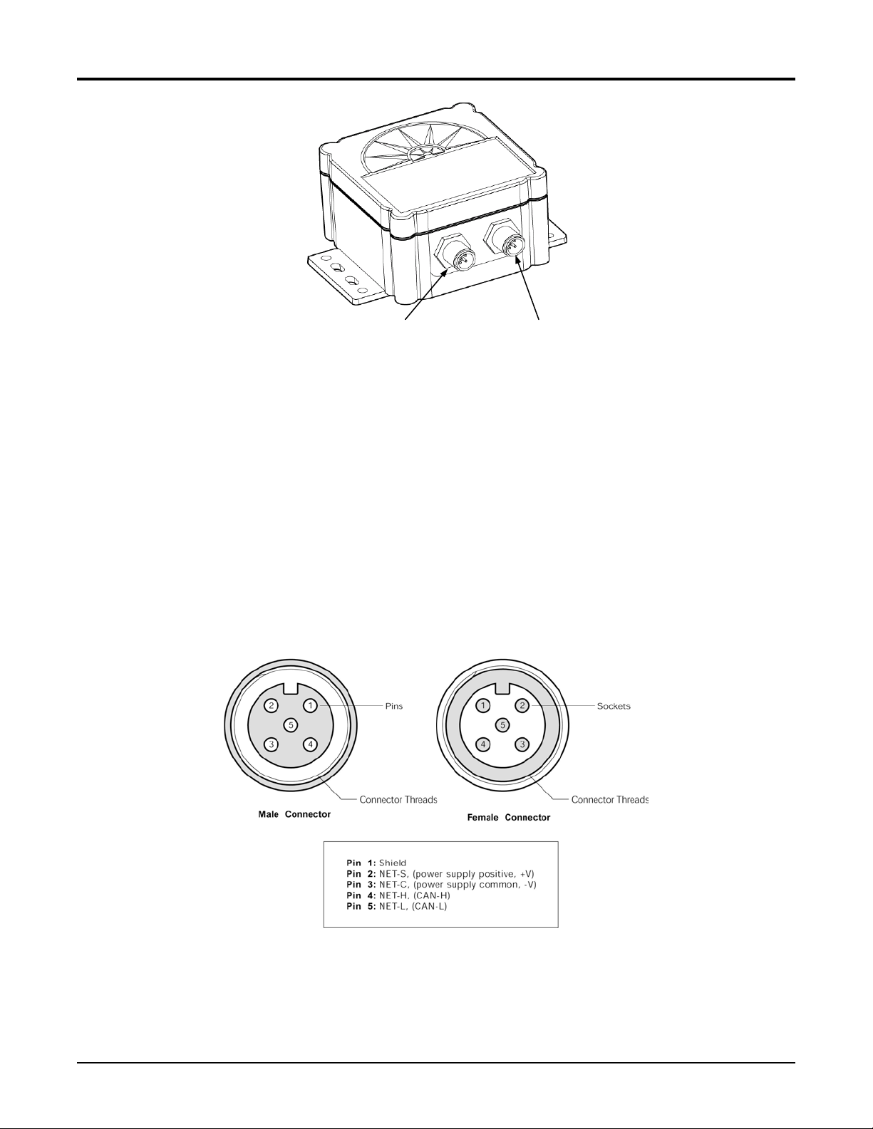
NMEA 2000 / Power
Connector
Figure 3 – NMEA 2000® / NMEA 0183 Interface Connector Locations
2.4.1 Connecting to NMEA 2000® Interface
NMEA 0183 Connector
The Maretron SSC200 provides a connection to an NMEA 2000® interface through a five pin
male connector (Figure 4). You connect the SSC200 to an NMEA 2000® network using a
Maretron NMEA 2000® cable (or compatible cable) by connecting the female end of the cable
to the SSC200 (note the key on the male connector and keyway on the female connector) as
shown in Figure 5 below.. Be sure the cable is connected securely and that the collar on the
cable connector is tightened firmly. Connect the other end of the cable (male) to the NMEA
2000® network in the same manner. The SSC200 is designed such that you can plug or unplug
it from an NMEA 2000® network while the power to the network is connected or disconnected.
Please follow recommended practices for installing NMEA 2000® network products.
Figure 4 – NMEA 2000®/Power Connector Face Views
Page 6 Revision 1.8
®®
®
Figure 5 - SSC200 with NMEA 2000
Connection Only
2.4.2 Connecting to NMEA 0183 Interface
The Maretron SSC200 provides a connection to an NMEA 0183 interface through an eight pin
male connector (Figure 6). You connect the SSC200 to an NMEA 0183 network using the
Maretron supplied 10 meter cable by connecting the female end of the cable to the SSC200
(note the key on the male connector and keyway on the female connector). Be sure the cable
is connected securely and that the collar on the cable connector is tightened firmly.
Revision 1.8 Page 7
SSC200 User’s Manual
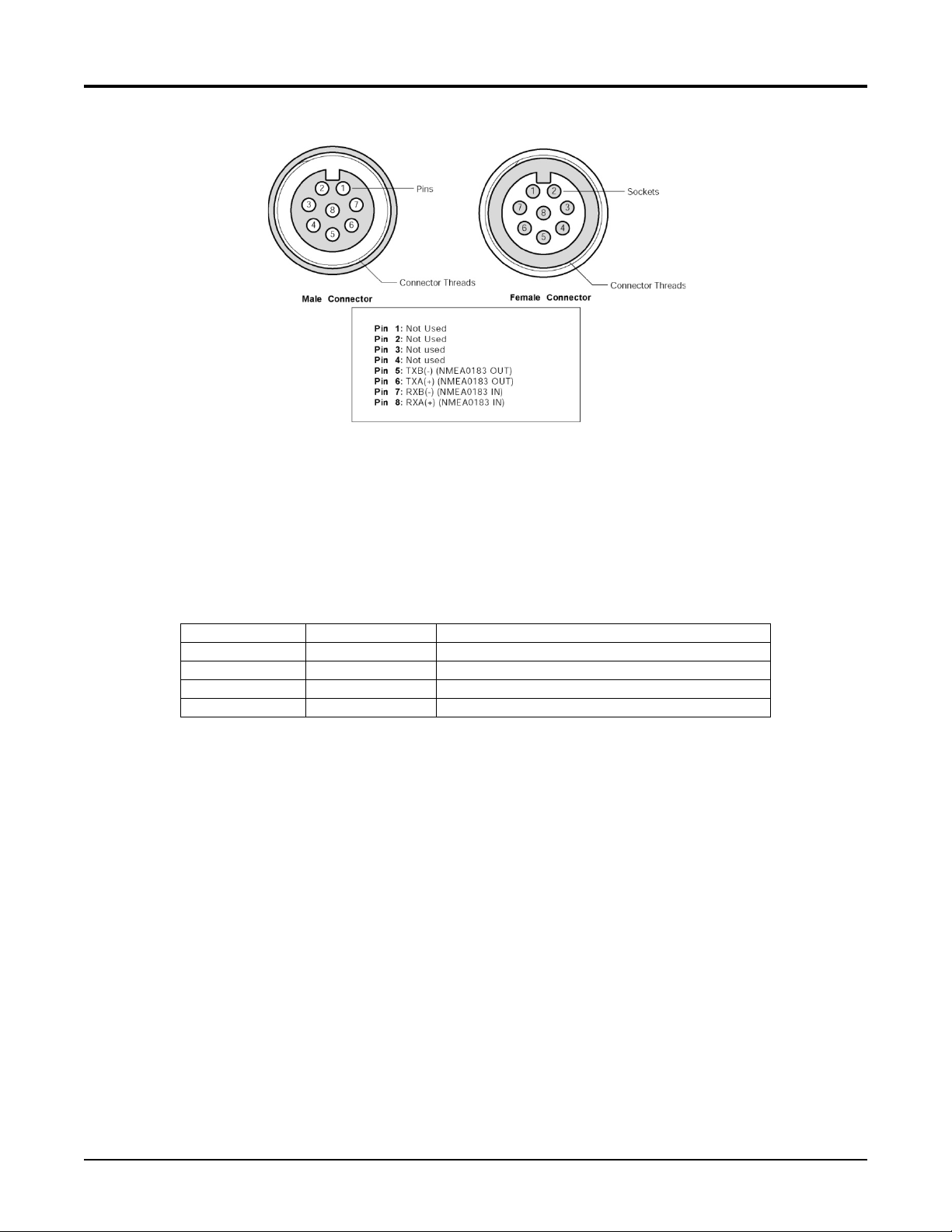
Figure 6 – NMEA 0183 Connector Face Views
Connect the other end of the cable consisting of individual wires using recommended practices
for installing NMEA 0183 products. Please note that NMEA 0183 does not have a standard for
connectors and the customer/installer should contact the manufacturer of the equipment to
which the SSC200 is being connected for information on how to properly connect the device to
the SSC200. The individual wires found within the cable have the following color coding.
Wire Color Name Description
Gray TXA Transmit Differential Output A Signal
Brown TXB Transmit Differential Output B Signal
Blue RXA Receive Differential Input A Signal
White RXB Receive Differential Input B Signal
Figure 7 – NMEA 0183 Cable/Wire Color Coding
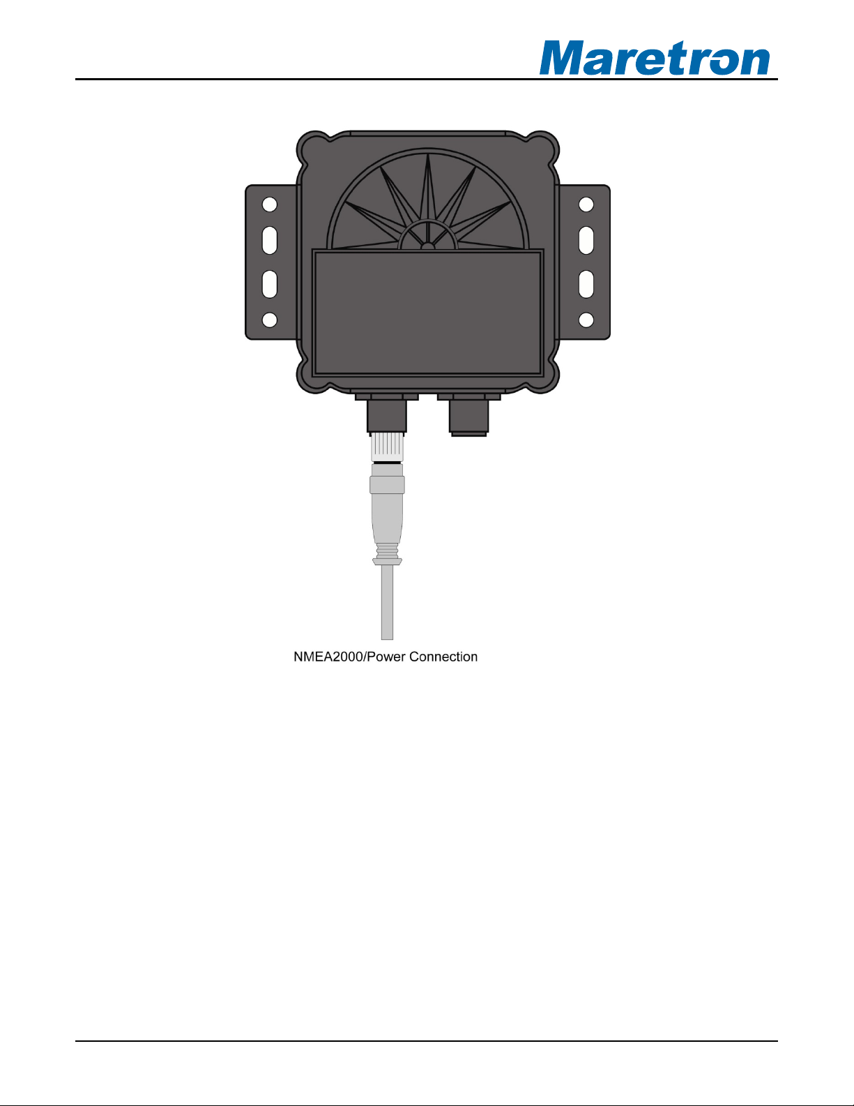
2.4.2.1 Power Connections
If the NMEA 2000® interface is connected, power is supplied to the SSC200 through the NMEA 2000® network connection.
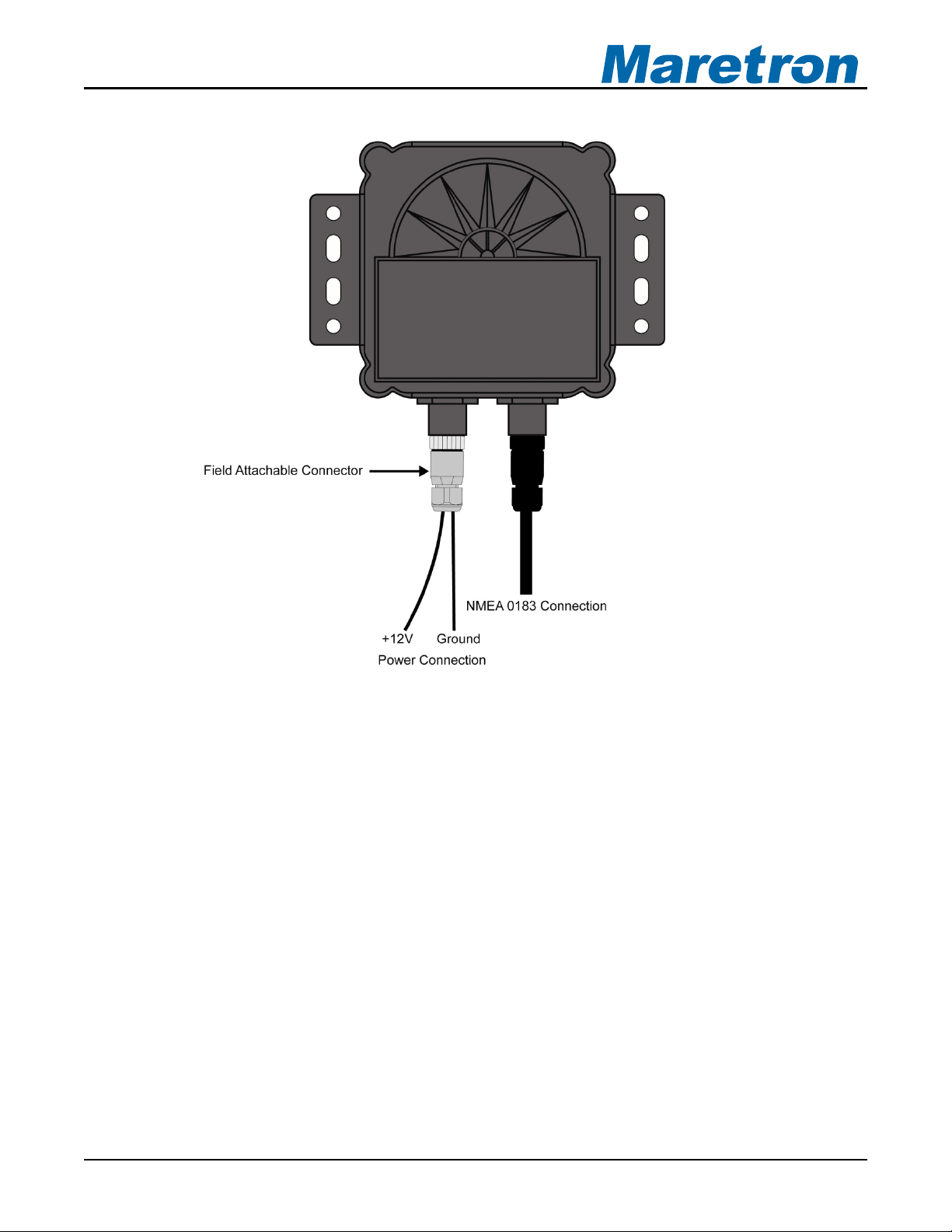
If only the NMEA 0183 interface is used, power connections must be made via the NMEA
2000®/Power connector. Using the included Micro Field Attachable Connector (Female),
connect two power wires (not included) to pins 2 and 3 of the field attachable connector (only
the two power pins need be connected) as shown in Figure 4 on page 6, assemble the
connector per the instructions packaged with the connector, and screw the connector snugly
into the NMEA 2000
®
/Power connector on the SSC200, as shown in Figure 8 below.
Page 8 Revision 1.8
®®
Figure 8 - SSC200 with NMEA 0183 Connection Only
2.4.2.2 Supported NMEA 0183 Baud Rates
The SSC200 compass supports NMEA0183 communication at both 4800 baud and 38400
baud. All SSC200 Compasses are shipped with a baud rate of 4800 baud. The baud rate may
be set to 38400 baud by connecting to the compass using a teminal emulator (See Appendix C
for details) and sending the following strings to the compass through the NMEA 0183
connection:
shell
This will cause the “cmd>” command prompt to be displayed
tm setbaud 38400
At this point, you must change the baud rate of your connection to 38400 baud to continue, as
the SSC200 has now been set to the higher baud rate.
tm storebaud
Revision 1.8 Page 9

SSC200 User’s Manual
This causes the new baud rate to be stored to non-volatile memory, so the compass will retain
this baud rate when it is powered down.
2.4.3 Connecting Both NMEA 2000® and NMEA 0183 Interfaces
The SSC200 can be simultaneously connected to both an NMEA 2000® network and an NMEA
0183 network.
2.4.4 Checking Connections
Once the NMEA 2000®/Power and/or NMEA 0183 connections to the Maretron SSC200 have
been completed, check to see that heading information is being properly transmitted by
observing an appropriate display. Refer to Section 7, “Troubleshooting”, if no heading
information appears, otherwise proceed to Section 3 entitled “Calibration”.
3 Calibration
In order to provide accurate heading indication, the SSC200 must be calibrated in the vessel
after installation. The two calibration procedures that must be carried out are magnetic
deviation calibration (Section 3.1) and installation-offset correction (Section 3.2).
These procedures should be carried out after the initial compass installation and again at any
time that the magnetic environment of the vessel has changed significantly (for example, new
cables have been routed near the compass or new equipment made of ferrous metal has been
installed near the compass).
WARNING: It is imperative that calibration procedures be carried out upon installation
of the SSC200 to ensure accurate readings.
3.1 Magnetic Deviation Calibration
Magnetic and/or ferrous items near a magnetic compass such as the SSC200 can cause
errors in the compass’ heading output. These errors are referred to as magnetic deviation.
The Maretron SSC200 compass can compensate for heading errors caused by magnetic
deviation by learning about the magnetic environment in which it has been mounted. This is
done using one of four possible magnetic deviation calibration procedures.
1. Maretron Display Product Initiated (Section 3.1.1)
2. Automatically at Power-Up (Section 3.1.2)
3. Through the NMEA 0183 Interface (Appendix A)
4. Through the NMEA 2000
All the procedures require that the vessel be turned in successive circles during which time the
SSC200 uses changing heading information along with readings from the angular rate sensor
to calculate hard and soft iron magnetic deviation. Upon a successful completion of deviation
calibration, the SSC200 stores the deviation values in permanent memory for subsequent
compensation. Under certain conditions (e.g., turning to fast or to slow), the SSC200 will not
successfully complete the calibration process and the SSC200 will not store the deviation
Page 10 Revision 1.8
®
Interface (Appendix B)
 Loading...