

Maretron ACM100 User Manual

®®
ACM100
Alternating Current Monitor
User’s Manual
Revision 1.2
Copyright © 2012 Maretron, LLP All Rights Reserved
Maretron, LLP
9014 N. 23rd Ave #10
Phoenix, AZ 85021-7850
http://www.maretron.com
Maretron Manual Part #: M001701
Revision 1.2 Page i
ACM100 User’s Manual
Revision History
Revision Description
1.0 Original document
1.1 Corrected AC sensor part number
Updated mounting drawing
1.2 Added sensed voltage and current range specifications
Added prohibition of red Loctite threadlocking compound and cleaning agents
containing acetone
Page ii Revision 1.2

®®
Table of Contents
1 Introduction ........................................................................................................................... 1
1.1 Firmware Revision .................................................................................................... 1
1.2 ACM100 Features .................................................................................................... 1
1.3 Quick Install .............................................................................................................. 2
2 Installation ............................................................................................................................. 2
2.1 Unpacking the Box ................................................................................................... 2
2.2 Choosing a Mounting Location ................................................................................. 2
2.3 Mounting the ACM100 .............................................................................................. 3
2.4 Connecting the ACM100 .......................................................................................... 3
2.4.1 NMEA 2000® Connection............................................................................... 3
2.4.2 AC Sensor Connections ................................................................................ 4
2.4.2.1 Single-Phase (Phase A) Connection ................................................ 5
2.4.2.2 Single-Phase (Phase A, B) Connection ........................................... 6
2.4.2.3 Three-Phase (Phase A, B, C) Connection ....................................... 8
2.4.3 Checking Connections ................................................................................. 10
2.5 Configuring the ACM100 ........................................................................................ 10
2.5.1 Device Instance ........................................................................................... 10
2.5.2 AC Device Type ........................................................................................... 10
2.5.3 AC Circuit Type ............................................................................................ 11
2.5.4 Reset Total Energy Recorded ...................................................................... 11
2.5.5 Advanced Configuration… ........................................................................... 11
2.5.5.1 Device Priority ................................................................................ 11
2.5.5.2 V,I,F Damping Period ..................................................................... 11
2.5.5.3 Power Damping Period .................................................................. 11
2.5.5.4 Current Transformer A ................................................................... 11
2.5.5.5 Current Transformer B ................................................................... 12
2.5.5.6 Current Transformer C ................................................................... 12
2.5.6 NMEA 2000® PGN Enable/Disable .............................................................. 12
2.5.7 Restore Factory Defaults ............................................................................. 12
3 Output Parameters .............................................................................................................. 12
3.1 Line-Specific and Line-to-Neutral Measurements ................................................... 13
3.2 Line-to-Line Measurements .................................................................................... 13
4 Maintenance ........................................................................................................................ 13
5 Troubleshooting .................................................................................................................. 14
6 Technical Specifications ...................................................................................................... 15
7 Technical Support ............................................................................................................... 16
8 Installation Template ........................................................................................................... 17
9 Maretron (2 Year) Limited Warranty .................................................................................... 18
Table of Figures
Figure 1 – Mounting the ACM100 .............................................................................................. 3
Figure 2 – NMEA 2000® Connector Face Views ....................................................................... 4
Figure 3 – Single-Phase (Single Line) Connection Diagram ...................................................... 5
Revision 1.2 Page iii

ACM100 User’s Manual
Figure 4 – Single-Phase (Dual Line) Connection Diagram ........................................................ 6
Figure 5 – Three-Phase Connection Diagram ........................................................................... 8
Figure 6 – Mounting Surface Template ................................................................................... 17
Table of Appendices
Appendix A – NMEA 2000® Interfacing .................................................................................... A1
Page iv Revision 1.2

®®
1 Introduction
Congratulations on your purchase of the Maretron Alternating Current (AC) Monitor (ACM100).
Maretron has designed and built your ACM100 to the highest standards for years of
dependable and accurate service.
Maretron’s ACM100 is a device which monitors AC power sources and outputs information
about these sources onto the industry standard NMEA 2000® marine data network. ACM100
output information is then displayed with networked NMEA 2000
Maretron DSM250 dedicated display or with NMEA 2000® compatible software such as
Maretron N2KView. The ACM100 can sense voltages up to 240VAC (line-to-neutral) and
currents up to 200A.
The Maretron ACM100 is designed to operate within the harsh demands of the marine
environment. However, no piece of marine electronic equipment can function properly unless
installed, configured, and maintained in the correct manner. Please read carefully and follow
these instructions for installation, configuration, and usage of the Maretron ACM100 in order to
ensure optimal performance.
®
equipment such as the
1.1 Firmware Revision
This manual corresponds to ACM100 firmware revision 1.0.0.
1.2 ACM100 Features
The Maretron ACM100 has the following features.
• NMEA 2000® Interface
• Waterproof Connectors
• Sealed Waterproof Enclosure
• Opto-Isolated from NMEA 2000® Eliminating Potential Ground Loops
• Monitoring of busses carrying AC power and transmitting
o Voltage
o Frequency
• Monitoring AC Power Sources such as Utilities and Generators and transmitting:
o Voltage
o Current
o Frequency
o Real Power
o Reactive Power
o Apparent Power
o Power Factor
o Total Energy Imported
o Total Energy Exported
• Can be used in the following configurations
o 120VAC single phase
o 120/240VAC split-phase
o 208VAC Y Three-phase (208Y)
Revision 1.2 Page 1

ACM100 User’s Manual
o 230VAC single phase
o 380VAC Y Three-phase (380Y)
1.3 Quick Install
Installing the Maretron ACM100 involves the following five steps. Please refer to the individual
sections for additional details.
1. Unpack the box (Section 2.1)
2. Choose a mounting location (Section 2.2)
3. Mount the ACM100 (Section 2.3)
4. Connect the ACM100 (Section 0)
5. Configure the ACM100 (Section 2.5)
2 Installation
2.1 Unpacking the Box
When unpacking the box containing the Maretron ACM100, you should find the following
items:
1 – ACM100 – AC Monitor
1 – AC Current Transformer with 5 ft. (1.5m) long cable (Part # M000630)
1 – Parts Bag containing 4 Stainless Steel Mounting Screws
1 – ACM100 User’s Manual
1 – Warranty Registration Card
If any of these items are missing or damaged, please contact Maretron.
2.2 Choosing a Mounting Location
Please consider the following when choosing a mounting location.
1. The ACM100 is waterproof, so it can be mounted in a damp or dry location.
2. The orientation is not important, so the ACM100 can be mounted on a horizontal deck,
vertical bulkhead, or upside down if desired.
3. The ACM100 is temperature rated to 55°C (130°F), so it should be mounted away from
engines or engine rooms where the operating temperature exceeds the specified limit.
Page 2 Revision 1.2
®®
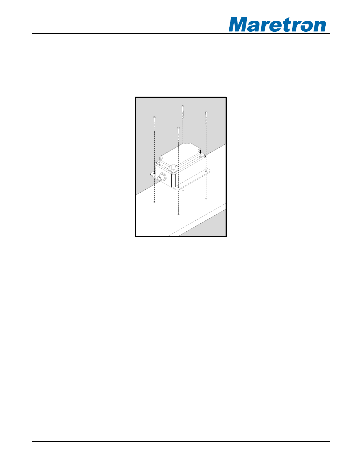
2.3 Mounting the ACM100
Attach the ACM100 securely to the vessel using the included stainless steel mounting screws
or other fasteners as shown in Figure 1 below. Do not use threadlocking compounds
containing methacrylate ester, such as Loctite Red (271), as they will cause stress cracking of
the plastic enclosure.
Figure 1 – Mounting the ACM100
2.4 Connecting the ACM100
The ACM100 requires two types of electrical connections: 1) the NMEA 2000® connection
(refer to Section 2.4.1), and 2) the AC sensor connections (i.e., current sensor(s) and sensing
voltage(s) connections), which are described in Section 2.4.2.
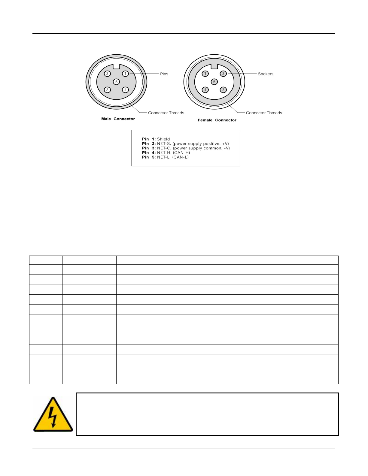
2.4.1 NMEA 2000® Connection
The NMEA 2000® connector can be found on the side of the enclosure. The NMEA 2000®
connector is a round five pin male connector (see Figure 2). You connect the ACM100 to an
NMEA 2000® network using a Maretron NMEA 2000® cable (or compatible cable) by
connecting the female end of the cable to the ACM100 (note the key on the male connector
and keyway on the female connector). Be sure the cable is connected securely and that the
collar on the cable connector is tightened firmly. Connect the other end of the cable (male) to
the NMEA 2000® network in the same manner. The ACM100 is designed such that you can
plug or unplug it from an NMEA 2000® network while the power to the network is connected or
disconnected. Please follow recommended practices for installing NMEA 2000® network
products.
Revision 1.2 Page 3
ACM100 User’s Manual
Figure 2 – NMEA 2000® Connector Face Views
2.4.2 AC Sensor Connections
The ACM100 sensor connections are made by connecting to the 12-pin terminal strip on the
top of the unit. First, remove the four screws at the corners of the unit detaching the splash
guard from the unit. On the bottom of the splash guard, you will find a label detailing the wire
connection to pin number assignments, which are repeated in the table below.
Pin # Signal Name Connection
1
2
3
4
5
6
7
8
9
10
11
12
V
V
V
V
V
V
A
B
C
Line
A
Line
B
Line
C
Neutral
Neutral
Neutral
I
A+
I
A-
IB+
I
B-
IC+
I
C-
WARNING: The voltages present on AC circuits can cause electrocution.
Before making any electrical connections to the ACM100, ensure that power is
removed from all AC circuits that will be connected to the ACM100. Only restore
AC power after all connections have been made to the ACM100 and the splash
guard has been re-installed.
Voltage Phase A Line
Voltage Phase B Line
Voltage Phase C Line
Voltage Phase A Neutral
Voltage Phase B Neutral
Voltage Phase C Neutral
Current Phase A Plus
Current Phase A Minus
Current Phase B Plus
Current Phase B Minus
Current Phase C Plus
Current Phase C Minus
Page 4 Revision 1.2
 Loading...