

MarelliGenerators M40FA640A/A MARK I User Manual

M40FA640A/A - Mark I
User Manual
Automatic Voltage Regulator for Three-phase Synchronous Generators
(Issued: 04.2010)
SIN.NT.015.6
Instruction Manual
Installation • Operation • Maintenance
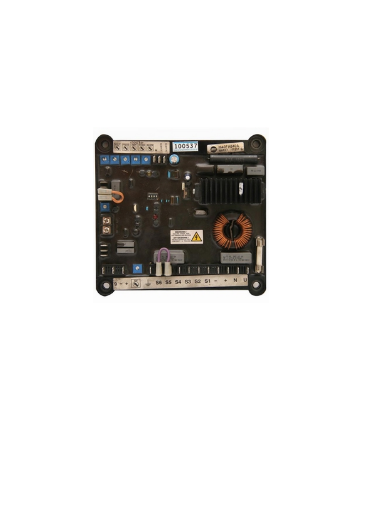
MARELLI AVR M40FA640A
hanada technology Co.,Ltd.
Page 1
INTRODUCTION
This Technical Note pr ovides gener al install ation and oper ating
information exclusively concerni ng the Marelli Motori regulator
code specified in the document, mounted on the Marelli Motori
synchronous generators specified in the next paragraph
“APPLICATION”.
Before the generator start and any types of regulation
operation, read carefully and completely t his Technical Note.
IMPORTANT NOTE: It is not the intention of this document t o
cover all the ins tallation or connection di agram variations, nor
does this manual provide information for every possible
contingency. The connection drawings provided with the
generator, the generator user manual and all the technical
information provided by Marelli Motori Technical Personnel can
integrate this Not e.
In particular, the connection drawings into this document are
provided only for e xplanation purpos es. They do not cover all
the application cases and not substitute the connection
drawings usually provided with the generator.
Should further information be required, please contact After
Sales Department (s ee the reference at the end of the page).
ENGLISH
SAFETY PRECAUTIONS
WARNING: when the regulation device is
energized (generator running), a lethal
(connection side) and at al l the par ts el ectri cally connect ed
to it. Furthermore, there are component s into the c ard that can
reach high worki ng temperature s, with high dan ger for the user
in case of direct contact.
personnel. Furthermore, pay attention to wait a time
interval sufficient for the device cooling-down.
suitable to assure t he user saf ety (i. e. isolat ed screwdr iver,
protection glasses and gloves).
Marelli Motori is under no liability for any damages which may
occur to the AVR, th e plant or the p ersons, or for l ost earnings ,
or financial loss, or system stoppages, due to missed out
Technical Note reading (both safety and installation/operating
instructions).
voltage is present at the top panel
Every wiring and/or mechanical installation
operation on the regulat or must be per formed only
in generator stop conditions, and only by skilled
Every regulation setting operation must be
performed with generat or running in no lo ad
conditions, by skilled personnel, using tools
SIN.NT.015.6 – M40FA640A/A
2
Issued 04.2010

DATI TECNICI - TECHNICAL DATA
INPUT/
ENGLISH
APPLICATION
The voltage regulator type “MARK I”, is suitable for
Synchronous Generators of MARELLI MOTORI make,
MJB series, size range 160-500 frames. This regulator is
proper to operate on machines rated from 10 up to 2000
kVA. The regulator is fully insulated in order to maintain
high reliability also with severe ambient conditions (high
level of humidity, dust, salt atmosphere), and in case of
high vibrations level. The regulator is proper both for single
and 3-phase operation.
REGULATION ACCURACY
VOLTAGE DRIFT:
RESPONSE TIME:
OPERATING TEMPERATURE:
EXCITER FIELD RESISTANCE:
OUTPUT DATA:
-
SUPPLY VOLTAGE:
-
-
POWER SUPPLY:
-
-
POWER DISSIPATED:
-
-
VOLTAGE SENSING:
-
±0.5%
a regime, per valori di tensione e carico nominali
steady state conditions, for rated Voltage and PF
±0.5%
variazione di tensione per variazione T
of voltage change for 50°C T
1 cycle (20ms-16.6ms)
-30°C ÷ +70°C
3.5Ω (min) ÷ 20Ω (max)
170 - 277V (50/60Hz)
1000 VA (max)
30 W (max)
170 - 270 / 380 - 415 / 440 - 480 V
(Three or Single Phase Sensing)
change
amb
amb
50°C
-
OUTPUT VOLTAGE (DC):
-
-
OUTPUT CURRENT (DC):
-
-
OUTPUT CURRENT (DC):
-
SIN.NT.015.6 – M40FA640A/A
80V (max, servizio continuo)
8A (max, servizio continuo)
(max, continuous)
15 A (max, in forzamento 1 minuto)
(max 1 minute forcing)
3
Issued 04.2010
VOLTAGE REGULATOR
M40FA640A/A
MARK I
ENGLISH
PAR
Va ric o mp
FREQ
VOL T
AMP
P
Q
60
Hz
RED
LED
A
B
8
6
9
-
+
ST AB SLOPE
YELLOW
LED
S6 S5 S4S3S2 S1
Three phase
voltage
refere nc e
ON
2
1 3
OFF
4
micro-switches 1-4
F
U
S
N U
-
+
E
Supply
Exciter
stator
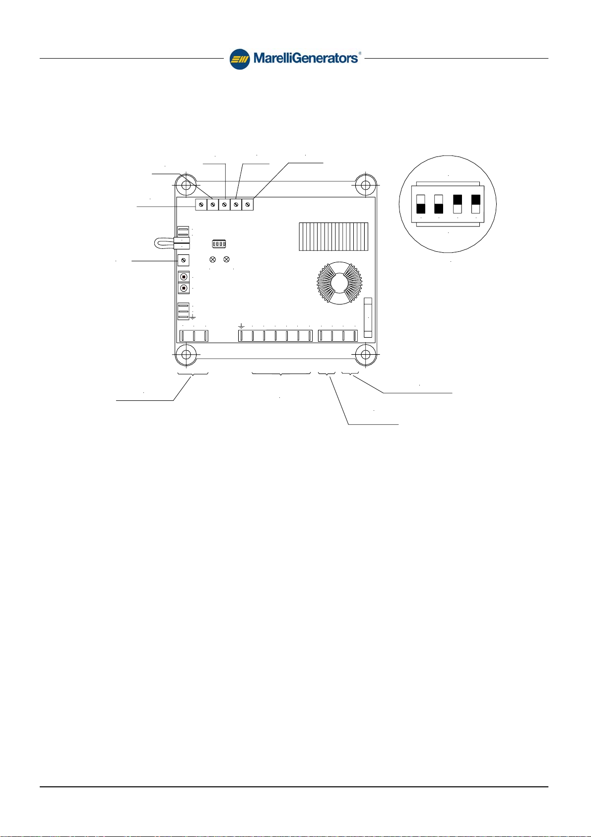
TERMINALS
Connection terminals are performed through FAST-ON
terminals. The terminals have to be connected according
the applicable wiring diagram, in order to avoid any
possible mistake in the wiring. The use of FAST-ON
terminals makes any operation on regulator (as
replacement, connection to accessories, setting up)
extremely simple.
POWER STAGE INPUT TERMINALS
“U”, “N” : terminals for power supply
VOLTAGE SENSING INPUT TERMINALS
“S1 - S2”, “S3 - S4”, “S5 - S6” are the terminals for three
phase or single phase voltage sensing.
POWER OUTPUT TERMINALS
“+”, “-”: output terminals (positive, DC, and negative, DC).
SIN.NT.015.6 – M40FA640A/A
4
Issued 04.2010
 Loading...