

Page 1

User’s Manual
BCM SYSTEM
Model No.: BN009
There is no User’s Manual because this equipment will not be sold to enduser directly.
Page 2

CONTENTS
1. PREFACE
2. PASSSIVE ACCSESS ENTRY FUNCTIONALITY
2.1. Door Unlocking
2.2. Engine Start
2.3. Engine Stop
2.4. Door Locking (Push switch)
3. ACTIVE ACCESS ENTRY FUNCTIONALITY
3.1. Door Unlocking
3.2. Engine Start
3.3. Engine Stop
3.4. Door Locking
3.5. Trunk Open
4. ENTRY SYSTEM OPTIONS
4.1. System Schematic
4.2. Modules
4.2.1. FOB ECU
4.2.2. Entry System ECU
5. SYSTEM CHARACTERISTICS
5.1. Antenna Areas
5.2. Exciter Locations
5.3. Switch Input Locations (Door handle)
6. ELECTRICAL CHARACTERISTICS
6.1. FOB
6.2. Entry System ECU
FCC WARNING
NOTICE
Page 3

1.Preface
This document describes the requirements and operation of the Passive Entry System. However, this
document is especially for the Entry system ECU (acronym for Electric Control Unit) and the FOB.
The FOB consists the following functionality for passive access and active access:
· Door unlocking / locking (however, only for request by means of switch operation)
· Trunk open (however, only for request by means of switch operation)
· LF decoding
· RF encoding
· Communication data encryption (cryptograph, anti-collision, rolling code and stuff)
And the entry system ECU consists of the following functionality:
· Door unlocking / locking
· Trunk open
· Engine start (/ stop)
· LF encoding
· RF encoding
· Communication data encryption (cryptograph, anti-collision, rolling code and stuff)
· LF antenna unit control
· Communication with the node ECUs connected to the body bus (e.g. CAN, J1850, customer
dependent bus)
As a further function, both the FOB and the entry system ECU provides the following function:
· Learning mode for programming the manufacturing data and stuff
· Data locking and password protection
· Diagnostic (based upon ISO9141 if required)
Page 4
LF RF
2.Passsive Accsess Entry Functionality
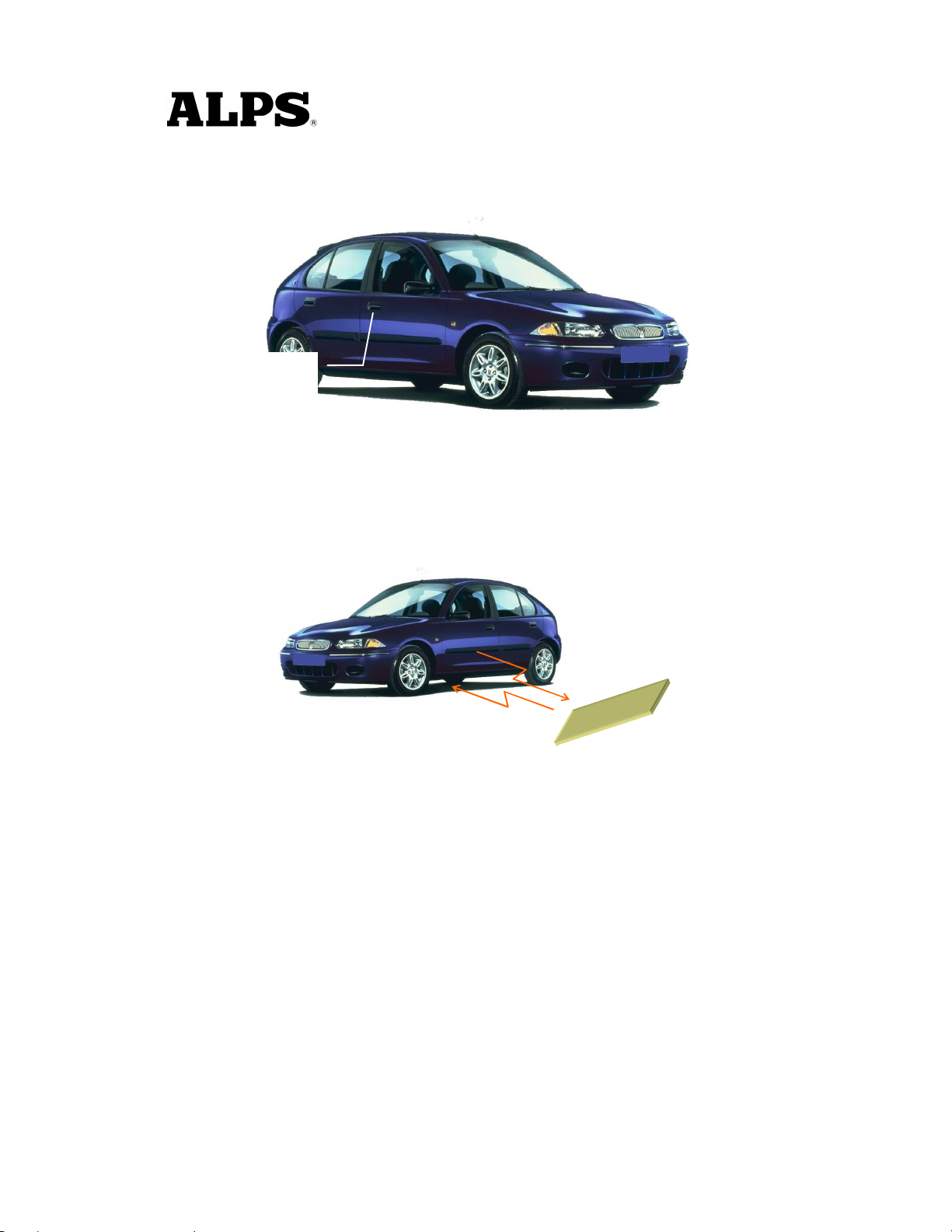
A handle sw located on, for example the door handles, mirrors and trunk lid will be used for proximity
check if user is in neighborhood of the vehicle. The switch input will trigger for unlocking and open the
doors and trunk.
Door Handle SW
Figure 1
2.1.Door Unlocking
· User pushes door handle sw.
· ECU sends LF-challenge via exterior antenna.
· FOB sends RF-response to the ECU.
· Door unlocking status is engaged.
· Doors are opened.
Figure 2
FOB
Page 5
RF
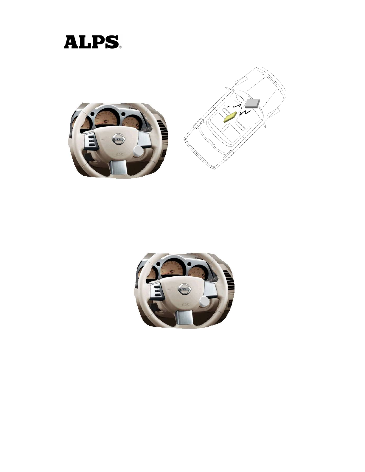
2.2.Engine Start
· User operates the engine start knob.
· ECU sends LF-challenge via interior antenna.
· FOB sends RF-response to the ECU.
· Immobilizer ECU receives and authorize the response.
· Engine controller ECU receives the authorization for engine strat.
· Start the engine.
LF
FOB
Figure 3
2.3.Engine Stop
· User operates the engine stop knob.
· ECU communicates with the other ECU for engine start request.
· Engine controller ECU receives the request.
· Stop the engine
Figure 4
Page 6
2.4.Door Locking (Push switch)
· User closes the door and pushes the switch (sensing of door locking switch).
· ECU sends LF-challenge via exterior antenna.
· FOB sends RF-response to the ECU.
· Door locking status is engaged.
· Doors are locked.
· (Indicates the door locking status by means of Flasher / Buzzer or stuff)
Figure 5
Page 7

3.Active Access Entry Functionality
3.1.Door Unlocking
Same functionality as the current one.
3.2.Engine Start
This function does not effect on the active entry system.
3.3.Engine Stop
This function does not have influence on the active entry system.
3.4.Door Locking
Same functionality as the current one.
3.5.Trunk Open
Same functionality as the current one.
Page 8
ECU
ECU
ECU
434
MHz
RF
LF
Y
Body Bus
Local Bus
LF
Exciter
LF
Exciter
LF
Exciter
LF
Exciter
As
Exterior Antenna
Interior Antenna
LF
Exciter
LF
Exciter
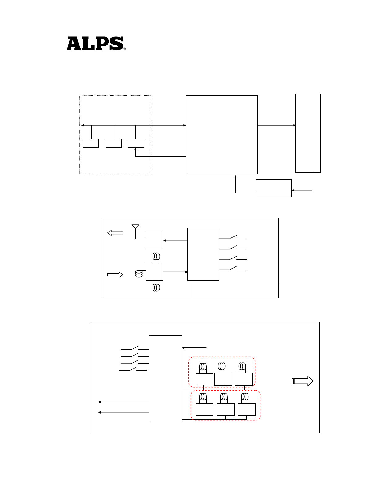
4.Entry System Options
4.1.System Schematic
4.2.Modules
OTHER ECUS
Body Bus
Local Bus
ENTRY SYSTEM ECU
Tuner signal
FOB
125kHz
LF (>2Kbps)
RF Tuner
4.2.1.FOB ECU
434MHz
125kHz
4.2.2.Entry System ECU
Dr Door handle
As Door handle
Trunk
Push knob
(Engine start knob)
Amp
X
Amp
FOB
ASIC
Emergency key (Transponder)
ENTRY SYSTEM ECU
MCU
Room1
Tuner signal
Room2 Room3
Dr
Lock
Unlock
Trunk
Panic
Room1: Console Antenna
Room2: Inst. Antenna
Room3: Trunk Antenna
Trunk
Dr : Driver Door Antenna
As : Assist Door Antenna
Trunk : Bumper Antenna
RF (>4Kbps)
125kHz
Page 9
As
5.System Characteristics
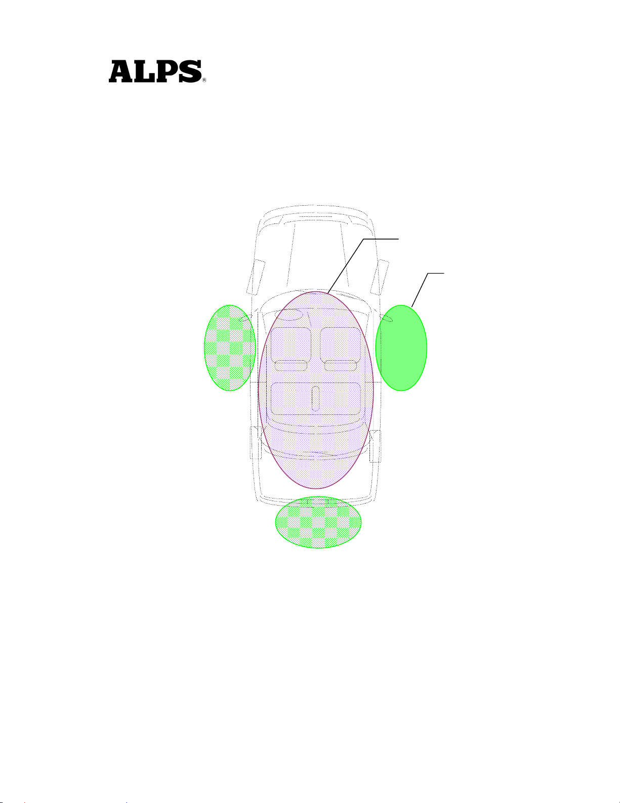
5.1.Antenna Areas
Exterior operating range: 0.8m to 1.5m
Interior operating range: Only inside the car
Number of the exterior exciters : typ.3, however, it is depending on the type of the vehicle.
Number of the interior exciters: max.4 (min.2)
Dr
Back
Figure 6
Interior
Exterior
Exterior antenna functionality:
· Unlock / lock doors.
· Open trunk.
· Activate / deactivate alarm system.
· Activate immobilizer
Interior antenna functionality:
· Deactivate immobilizer
· Engine start
Page 10
Interior
As
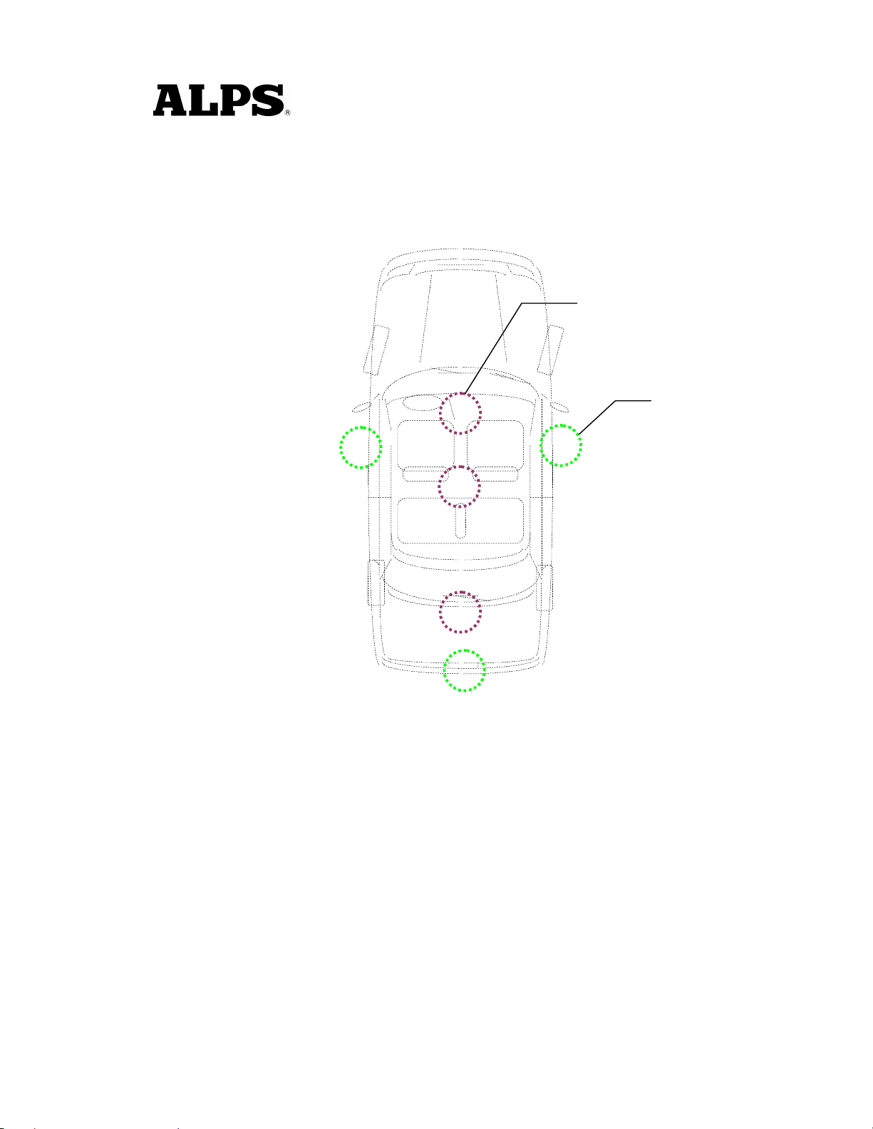
5.2.Exciter Locations
Exterior exciters: 3 doors
Interior exciters: 1 Center Console
2 Inst panel
3 Trunk
Dr
Exterior
Bumper
Figure 7
Antenna location can be different among of type of the vehicle (e.g. coupe, sedan, mini and stuff).
Page 11
As
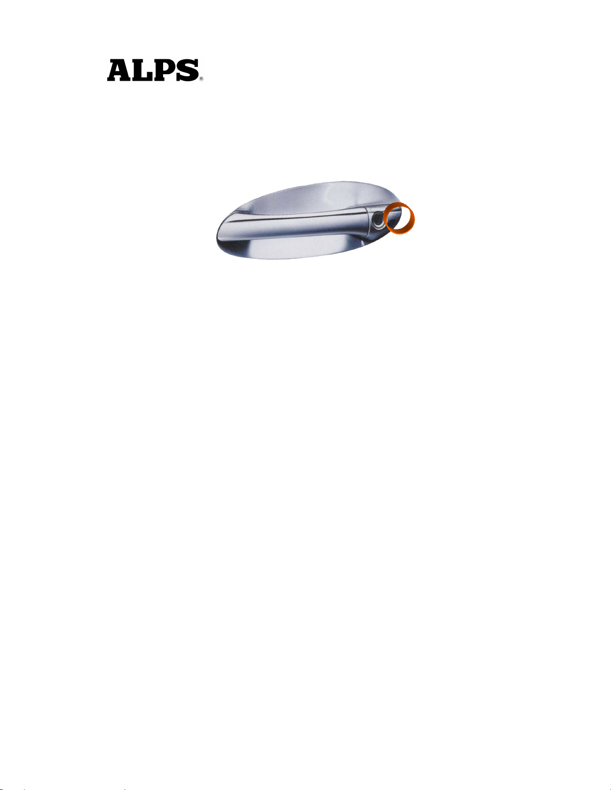
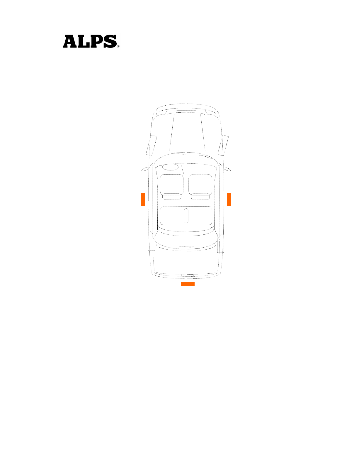
5.3.Switch Input Locations (Door handle)
There are some switches, for instance the door handle contact switch will be used as a triggering for
unlocking and open the door.
Switch inputs: 3 doors
Dr
Trunk
Figure 8
Switch inputs can be different among of type of the vehicle (e.g. coupe, sedan, mini and stuff).
Page 12

6.Electrical Characteristics
6.1.FOB
· ASK / FSK modulation
· Operating supply voltage 2.5V ~ 3.3V (3.0V Battery)
· Operating supply current < 35mA
· Stand-by current < 10.0uA
· Operating ambient temperature -10oC to +60oC
· Antenna direction 3-Dimension (X, Y, Z), to be considered
· Battery life 1.5 Years (Low battery indication is considered)
6.2.Entry System ECU
· Operating supply voltage 9.0V ~ 16.0V
· Operating supply current < 55mA
· Stand-by current < 4.0mA
· Operating ambient temperature -30oC to +80oC
·
Page 13

FCC WARNING
Changes or modifications not expressly approved by the party responsible for compliance
could void the user’s authority to operate the equipment.
NOTICE
This device complies with Part 15 of the FCC Rules and RSS-Gen of IC Rules.
Operation is subject to the following two conditions:
(1) this device may not cause harmful interference, and
(2) this device must accept any interference received, including interference that may
cause undesired operation.
 Loading...