


V12-CE SETUP MANUAL
V12-CE
SETUP
MANUAL

V12-CE SETUP MANUAL
INTRODUCTION
This document is not meant to act
as a complete instruction manual
– it has been written to support the
build instructions that come in the
kit, as well as suggest a variety of
tips that can improve the way the
car drives. It is aimed mainly at
The V12 ‘CE’ kit shares many of
the same parts as the older V12
kits. However, both the main chassis plate and new front suspension
plate are now made from either
GRP or Carbon composite material,
and these need careful preparation.
Round the edges with a light rub
down with 400 wet/dry paper (a
V12 runs close to the ground and
smoothing these edges prevents
the chassis from grabbing at the
carpet during a race). Then carefully seal the edges with a thin
layer of Super Glue to help prevent de-lamination during impacts.
Club racers at WSMCC, but does
make reference to the changes
required for racing at other clubs
which have different track sizes
and layouts, and for racing at
National level (to current BRCA
rules) too.
It is also assumed that the driver
has bought the additional differential rear axle to use on the car.
Buying one is not 100% essential, but most drivers agree that
you will get a better driving car if
you install one.
1. PARTS PREPARATION
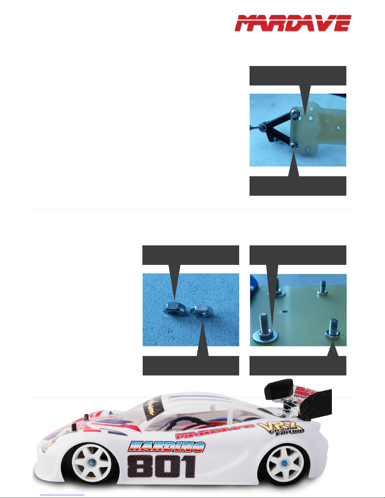
On the CE chassis, the wishbones
mount directly on the front suspension plate. They must be mounted
at on the front plate and the other
way up from the standard V12 kit.
Mount them with the lugs facing
‘upwards’. Do not add shims or
washers under the front end of the
wishbones to give you castor like
you used to on an old V12 chassis.
You’ll add shims, but you’ll do this
under both ends of the wishbone to
alter the ride height once the rest
of the car is built up; castor is best
changed by angling the plate itself.
It is best to get castor through
angling the whole plate, not by
angling the wishbones on the
plate. We have found that forcing
a twist in the wishbones by adding
spacers under their front end is
good to start with, but the plastic
the wishbones is made from has a
tendency to ‘creep’ and will try to
re-mould itself back it its original
shape over time. The problem
is that your left and right hand
wishbones won’t always creep at
the same rate, and after a week or
two you’ll have different castor on
each side – not good for consistent handling!
2. FRONT END
Wishbones lug side up.
Mounted at on the front plate.
No shims under here!
NEED UPGRADES & PARTS? WWW.MARDAVE.COM
V12-CE SETUP MANUAL
The holes you use to bolt the wishbones to the front plate depend
on the type of track you run on
and how you like the car to han-
dle. Wide wishbone spacing helps
prevent grip roll in the fast sections
but reduces steering a bit through
slow, tight sections of tracks; a
long wheelbase promotes stability at high speed while a shorter
wheelbase allows faster changes of
direction. At this point many drivers ditch the self-tapping screws
that come in the kit and use slightly
longer (12mm) button head M3
machine screws to give a stronger
mount when xing the wishbones
to the plate. Since the 4 holes for
each screw are quite close together you should also use a relatively
large diameter M3 washer under
the each of the screws’ heads to
help spread any loads. For the
time being, screw them all down
tight.
2.A. FRONT END
In this case, wishbones set to
“long and wide”.
M3 washer between screw
head and plate.
NOTE: do not use less than 2mm
spacing on the rear two screws
– doing so will allow the head
of the rear screw holding the
wishbone to the front plate to hit
the chassis and tweak the front
plate.
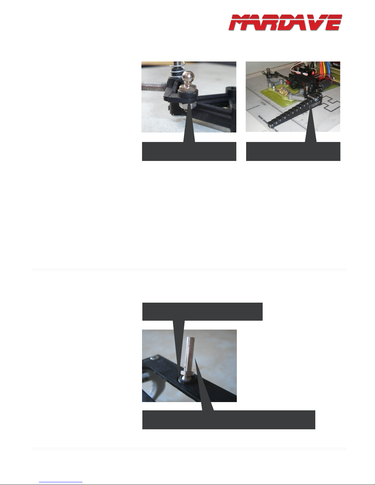
Now, add the central screw, but do
not add anything between the front
plate and chassis - we have found
that having a bit of ex in the plate
gives better front bite mid-corner
and more even tyre wear. Tighten
the screw’s top nut so that it compresses the plate to give about 1.5’
camber.
2.B. FRONT END
1mm thick washer under front bolts.
No washer under rear bolts.
Standard Nut
M3 “Low-Prole” nut is about 1mm
thinner than a standard nut.
V12-CE SETUP MANUAL
The steering system is easier - assemble all the parts and make sure
they all move freely. Add a 2mm
shim under the balls on the steering
arm (and use the bottom holes in
the servo saver) to get the steering
track rods as horizontal as possible
and minimize bump steer.
Lastly, make sure that the wishbones are seated level. Sometimes they can sit unevenly (this
can happen if any mould ashing
is not trimmed off the wishbone
mounts or steering blocks during
the build, or from racing impacts).
To check the wishbones, put the
chassis on a at surface, centre
the steering and measure the
clearance of the stub axels off the
ground. Left and right sides must
be identical. If they are not, check
for mould ashing and trim it, check
that kingpins and stub axels are
straight and replace any defective
parts.
2.C. FRONT END
“Ride Height” of left and right stub
axels must be identical.
Approx 2mm of spacers under the
pivot ball to eliminate bump steer.
This is almost identical to all other
V12 kits, the only difference is the
damper tube. Assemble the pod
and add the damper tube’s ball
stud, axel bearings and diff. Some-
times the rear pod’s pivot ball can
be stiff when tted in its hole in the
pod base plate. This is not good.
It is wise to give the ball a light rub
down by spinning it up in a drill and
polishing it with 400 wet/dry – this
will give a smoother movement, but
be careful not to make it so small
that you get any slop!
3. REAR END
If the rear pivot ball is tight in the cup, remove
it and sand it smooth with wet and dry paper.
This pivot ball has had a rear guide pin added to it via a grub screw.
The ball can rotate freely in the cup with just the weight of the pin.

V12-CE SETUP MANUAL
Next, add the rear spring screws
and nuts to the back of the chassis.
Add a washer between the rear
guide pin and the chassis – this
will stop the pin digging into the
chassis and reduces the risk of it
shaking loose or pulling through
the chassis in a big impact (new
part V9BT does this for you!). At
this point, check that the rear pod is
moves freely, sometimes the hole
in the pod’s base plate where the
pivot pin goes through needs to be
reamed out.
NOTE: this is just the hole in the
base plate itself, NOT the o-ring
and not the hole in the o-ring
holder!
3.A. REAR END
M3 washer under the rear pin – this
will help stop chassis denting.
If you are using large diameter rear
tyres (50-52mm diameter) then a
1.0 - 1.5mm thick washer under the
front pivot ball can be a good idea.
With tyres this size you’ll have to
loosen the rear springs right off to
get 3.5mm ride height. This will
give you a nice wide gap between
the bottom of the rear pod and the
top of the chassis but can, in fact,
bring the bottom of the rear pod
close to horizontal when the car
is sat at ride height. Horizontal is
not good for handling when you
accelerate – run the front of the
pod angled up to be at least 2mm
higher than the rear. For smaller
diameter rears you can remove
washers from under the pod’s ball
joint, or use none at all.
3.B. REAR END
Approx 1.5mm clearance be-
tween pod and chassis when the
car is resting on its wheels.
FOLLOW US! WWW.FACEBOOK.COM/TEAMMARDAVE

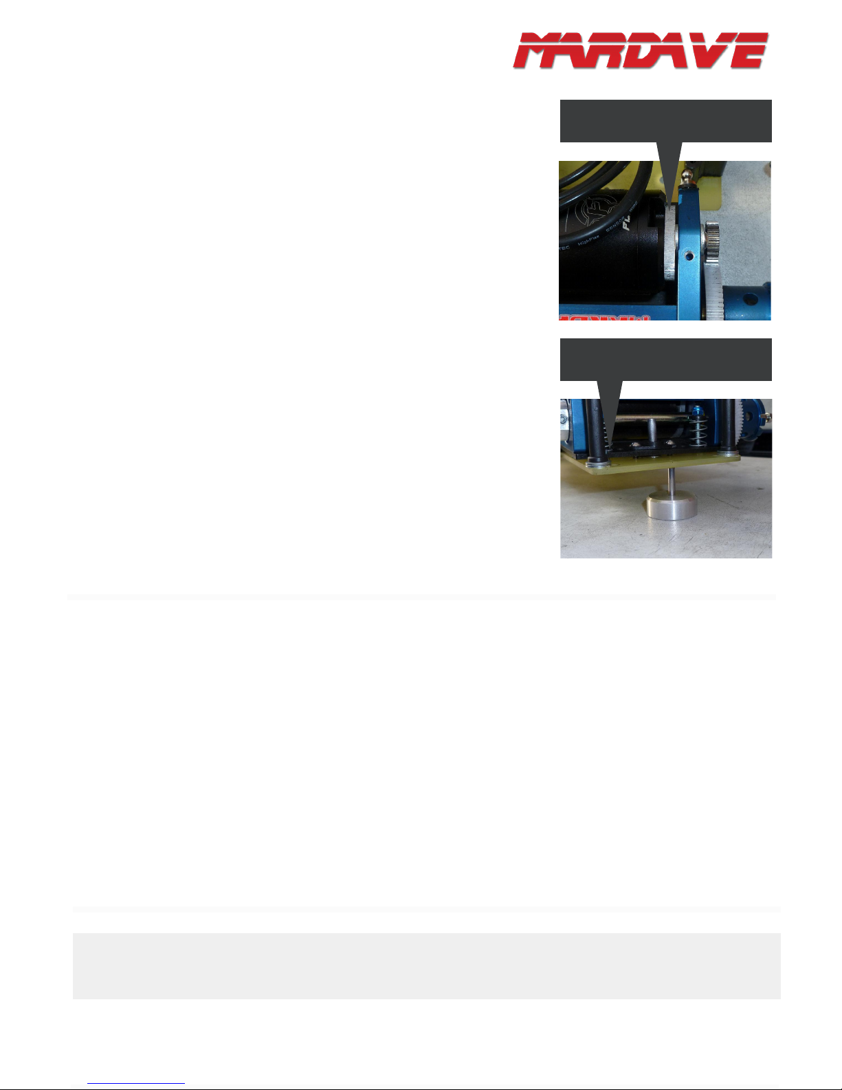
V12-CE SETUP MANUAL
The new, adjustable rear pod is different – ride height is changing by
swapping the axle bearing cams;
rear spring tension is only used to
get the required chassis droop and
is then left alone. The means no
washers are needed under the front
pivot ball, even if larger tyres are
used, resulting in your whole pod
(and CoG) being up to 2mm lower.
Just remember that when you
change the cams your gear mesh
will also need changing.
3.C. REAR END
Use a “Low” cam as your rear
wheels wear down.
Use a “High” cam when your
rear wheels are new and up to
51mm diameter.
This is a new part for this kit and
has a big impact on car handling.
The short story is that it affects
how the rear of the car behaves
as you go through corners. The
longer story is that oil thickness
changes the speed of the piston,
which changes how far/fast the
chassis can roll as you corner
which, in turn, affects how weight
is transferred and the outside tyre
is loaded up. Rear spring stiffness
/ diff tightness also come into play
and you risk some really poor handling if any of the settings are out!
Getting it right is a careful balance
of oil thickness, diff tightness and
spring rate.
Always keep the damper tube
topped up with oil. NOTE: There
is a difference between the units
used to measure oil thickness.
WT is not the same as CST so
30,000wt oil will be different to
30,000cst oil.
30,000wt oil is good on larger,
faster tracks and down to
12,000wt is good if you need
faster weight transfer and quicker
steering response on tight tracks.
Re-ll the tube every 3-6 runs,
whether it feels like it needs it or
not - wipe excess off the rod and
clean the inside of the tube with
motor spray. Pour a small amount
of oil into the tube and smother
the rod’s grooves in the stuff.
Slowly slide the rod into the tube
and give it a bit of a bounce and
twist as you push it in so that the
oil is evenly distributed. Expect
to get some oil squeezing out of
the breathing holes and some left
on the rod once it is fully in – this
way you know it is completely full
each time re-ll it.
As for handling:
1. Rear end ‘hops’ on accelerate out of corners - softer rear
springs, lighter damper oil or
loosen the diff.
2. Inside wheel front wheel lifts
(or car grip rolls) in corners harder rear spring and damper
oil use smaller diameter, harder
tyres.
3. On-power understeer out of
corners - loosen the diff; tighten it
for oversteer.
4. DAMPER TUBE
NEED UPGRADES & PARTS? WWW.MARDAVE.COM

V12-CE SETUP MANUAL
Recent BRCA ruling now recognises three forms of power for
running a Mardave / GT12 car –
4cell/G2, 1s LiPo/13.5t brushless
or 2s LiPo/21.5t brushless.
4-CELL/G2:
This is a very easy system for a
beginner to use - components are
cheap and reliable and there is a
wide variety available. However, it
is not so suitable for top end competition because getting the very
best out of a motor and cell is extremely time consuming, expensive
and difcult.
For this system, only the Mardave
G2 motor is eligible, speedos
must retail for under £65 and have
reverse but there is free choice of
cells. The CE kits come with a battery tray that is perfect for the 4-cell
packs.
1S LIPO / 13.5T
BRUSHLESS:
Slightly more powerful than the
4-cell/G2 system, zero maintenance and the most popular system for top end club and National
racing. However, the low voltages
of the 1s LiPo packs mean that
speedo choice is tricky – only a few
(expensive) speedos work properly,
and cheaper ones will need an additional voltage booster installed.
Speedos do not need reverse.
The most popular speedos are:
1. HobbyWing 1s: install the
508 version of the software for
full ‘blinky’ mode. This speedo is
slightly larger than the other speedos below, but it is the cheapest at
about £110 in the UK (or £70 from
Hong Kong).
2. LRP SXX Stock Spec: probably the most expensive of the
three (around £175 UK price)
but comes with the best warranty
and manufacturer backup too. If
possible, get the Version 2 unit
as some software versions on the
Version 1 units can be less reliable than others.
3. Nosram Pearl Version 2: essentially the same as the SXX V2,
but in a red box rather than a blue
one. Don’t get the V1 units as
these don’t have 1s LiPo capabil-
ity. New cost is usually around
£150.
4. Fusion Exceed: comes with a
perfectly good motor for £95 but
will need a voltage booster tted.
Not eligible for National racing as
it has no ‘blinky’ mode.
Motors can be any 13.5t from the
BRCA EB list (there is no restric-
tion of price any more). Popular
choices are the HPI Flux, Fusion
Exceed, Team Powers Plutonium.
The lexan battery tray that comes
in the kit will take most varieties of
1s LiPo cell and offers a degree of
extra protection too. Mounting the
cells in the designated place will
give a reasonable balance and
setup for medium to high speed
tracks.
Another option is to use ‘Cobra’
battery boxes to hold LiPo cells
and to mount them lengthways
(slightly to the left) down the chassis rather than across it. This will
get the weight closer to the centre
line of the chassis and is generally
better for faster changes of direc-
tion and faster, atter cornering. If
you choose to do this you should
position the cell, speedo, servo
and receiver very carefully to help
counterbalance the off-set weight
of the motor.
2S / 21.5T
BRUSHLESS
A new idea but extensive testing
has proved it to be very close to
the 13.5t / 1s setup, with none of
the low voltage problems. The
BRCA support this setup for club
racing but is not recognized at
National level.
For cells there are 3 main
choices:
1. Hard-cased, mini LiPo packs
used in the micro off-road buggy
classes. Small, very light but
still enough punch and capacity
to last an 8 min race. There are
battery trays available from Mardave that house these perfectly.
2. New 1s/2s packs for GT10
cars (Intellect CC2S3200V7 or
Yokomo YB-P228BE). Same
physical size as a standard 1s
pack (so t the standard cell
holders) but are internally wired
to give 7.4v.
3. “Shorty” packs used for
1/10 buggies. Taller than the
1s/2s packs (25mm compared
to 18mm) and are signicantly
heavier too. However, they offer
faster re-charge times between
races
For speedos and motors try
a HobbyWing “Just Stock” or
SpeedPassion Citrix or Reventon
“S” speedo and any 21.5t motor
that has a xed endbell (HobbyWing Stock, SpeedPassion V2 or
V3 Ultra Sportsman etc).
5. POWER: CELLS, SPEEDOS AND MOTORS

V12-CE SETUP MANUAL
The chassis is drilled for a standard
size (Touring Car size) steering servo to be mounted on the right hand
side of the chassis. This is ne for
oval Hot Rod racing but does not
give an ideal weight distribution for
circuit racing.
You’ll get a better balance if you
mount the servo on the left hand
side of the chassis. It is also a
good idea to invest in a ‘low-prole’
type servo (eg Savox 1251MG or
Futaba s9550 for example) since
these are short front to back, and
using these will free up some more
room for cells and electrics in the
chassis. Choosing a servo with
fast movement (<0.10 sec to 60’ at
6V) and reasonable torque (>4Kg/
cm) is also wise. Dedicated 1/12
scale servos can be good as they
are light in weight, just as fast and
usually have lower current draws,
but they are often longer in the
body (so take up more room) and,
as they are so slim, they need to
be raised off the chassis so there
is clearance for the servo saver to
move freely. It is a close call between the two types and really depends on budget and how/where
you plan to mount your cells.
NOTE: the holes that come predrilled in the chassis are designed to accept Futaba makes
of servo. The holes are spaced
so that the central output spline
on most Futaba servos is dead
centre on the chassis. Savox servos do not have the
same position for their output splines and, although the
1251MG model will t the holes
as they come, it will not be
dead centre.
If you choose to re-drill your
servo holes, mark them extremely carefully. Get your steering
assembled, mount the track
rods onto the servo saver and
then mount that onto the servo
itself. Position the servo so that
the track rods are perpendicular
to the centre line of the chassis
and this will give you reasonable
Ackerman change.
6. SERVO
Lexan shells are lighter, ABS ones
can be a little tougher. Some good,
and popular choices are :
Lotus GT1: most front end downforce of the common shells. Good
on slower, twisty tracks, but you’ll
need to add a bigger rear wing
and probably use small diameter,
harder compound front tires to stabilize it on faster tracks.
Mazda Speed 6: good aerodynamic balance makes this the safest,
most forgiving shell to drive.
Ascari GT3: half way between
the Lotus and Mazda for handling.
Common favorite for many drivers.
GT2 ‘Wedge’: can look nice,
but can also look like a piece of
cheese! Aside from looks, be very
careful when mounting it on your
chassis as the front/rear position
has a massive effect on aerodynamic balance – 2mm forwards
gives oversteer, 2mm backwards
gives understeer. Front and rear
wheel mould lines are not an ideal
shape.
Calibra: another good looking
shell but complex molding splits
easily and a high roof line and
high rear wing positions make
it unstable / prone to grip roll
through high speed corners.
Porsche 911: Soon to be released.
All the above are ne for club
meetings. Only the Ascari, Lo-
tus, and GT2 shells are permitted
for Nationals.
A nal word on bodies – many
drivers suggest investing in a set
of vertical rear posts or a V10M
‘Banger Mount’ and have these
mounted to come through your
shell under the rear wing. If you
turn them so the body pin holes
face front to rear the pins are
then easy enough to get in and
out.
7. BODY SHELL
VISIT OUR FORUM! WWW.MARDAVE-FORUM.CO.UK

V12-CE SETUP MANUAL
Ofcial Mardave bumper plates will
be released soon. Until they are,
cut a 45mm x 125mm rectangle
of 3mm nylon sheet, round off the
front corners and mount it to the
chassis using the two holes usually
used for the front body posts. Drill
another pair of holes in the bumper
plate, just in front of the edge of
the chassis, and mount the body
posts through these. This gives the
option to position the posts further
forward for better support of the
front of the shell, and body posts
could spaced from side to side to
avoid any awkward moldings in the
shell. Lastly, cut and shape some
15mm deep foam, punched holes
in this to go over the body posts,
and it is job done.
8. FRONT BUMPER
It can be worthwhile to have differ-
ent bumpers to t different shells.
Bumper plate bolted to chassis and
body posts bolted to the plate.
9. GENERAL SETUP
Any small, light, rear wheel drive
car is very delicate to set up right
- small changes have a big effect
on the way the car drives. Below
are some tips that should keep you
pointing (mostly) in the right direction.
TRYRES:
The most important setup tool are
your tyres, being on the right tyre
at the right time is 90% of getting
your car running well. UFRA pink
‘Medium’ (part number V54P) is
extremely popular as the rear tyre,
but front tyre compounds can vary
widely depending on track layout,
grip level and driver preference.
The JAP range are good - ‘shore’
ratings are a good indication of grip
with low shores (38’ for example)
giving more grip than the harder
52’ shore. JAP ‘Medium’ fronts are
actually the softest and offer most
grip. Start with a pair of 44’ or 46’
fronts, and get a pair of hard JAP
50s and some softer JAP Medi-
ums so you can test what works
best for you.
ADDITIVE:
Be careful. UFRA Pinks can take
additive twice a day (maximum)
with no ill effects, but JAP fronts
can get over-softened easily.
Most front tyre compounds pick
up most of the additive they need
straight off the track, but some
can be applied on the inside 1/3
of each tyre if you need extra
bite. Using additive more than
3 times a week on any tyre will
over-soften it – the structure of
the rubber changes and the tyres
just fall apart. A good strategy is
to buy multiple sets of the same
compound and run each tyre just
twice each meeting. Sure, this
means an increase in expense to
begin with but they last longer in
the long run.
Contact have recently released
a range of tyres for the Mardave
cars. Initial testing indicates
that grip is good, compounds
take additives well and wear is
not excessive. They are more
expensive at £6 (rears) or £7
(fronts) but they do come ‘trued
and glued’ which saves a lot of
mess. Their 32’ shore rears and
either 42’ or 45’ shore fronts are
popular, but true them down to
47mm (front) and 50mm (rear_
for best results. Their drawback
is that the wheel rims have no
lip on the outer edge – the tire
is much more prone to chunking
when you hit something. >>

V12-CE SETUP MANUAL
Once you have run any set of tyres,
store them in an airtight container
or bag. This increases their life
by not allowing them to ‘dry out’
between meetings. It is also a
good strategy if you ever run your
car at a club that does not allow
the use of additive – there is usually enough left in your tyres from
the last meeting when you did use
additive to see you through the
rst couple of rounds at the non-
additive club when grip is likely to
be lower.
After every race, check that your
tyres have not started to come
unstuck from the rims. Even the
smallest unstuck area will encour-
age grip roll. Use either EvoStick
or Super Glue to re-attach the tyre
to the rim.
Lastly, it is vital to round off the inside and outside edges of all tyres.
This will help prevent the outer
edge ‘rolling under’ during heavy
cornering. Grip roll is likely if this
ever happens.
FRONT SUSPENSION:
Since this is such a simple system
it requires very little work done on
it. However, since the steering
system is so direct, the work you do
need to do is extremely important.
Make sure each part moves completely freely and there is no stick-
ing or binding. If anything feels
stiff, disassemble, clean and
re-assemble. Check that kingpins
are not bent, that track rods have
not been knocked out of alignment, that ball cups have not got
grit in them or have too much play
and that bearings rotate freely.
REAR SUSPENSION:
Again, very simple, but very important too. The front ball joint can
gather dust and get stiff. Remove
the ball from time to time and
clean. Taking the ball in and out
too many times though causes the
cup to wear and the ball can then
be easily knocked out during a
race. If this happens, replace the
pod plate straight away. Use the
rear spring nuts to adjust your ride
height and chassis tweak (more
on that in a moment).
As the rear tyres wear down you
will have to change the spring
tension again (or change the axel
bearing cams if you have the ad-
justable alloy pod). Always leave
at least 1.2mm clearance between
the bottom of the rear pod and the
top of the chassis when the car
is resting at its given ride height.
Less than this and the pod will hit
the chassis as the rear suspension compresses in the corners,
leading to poor handling.
DIFF:
This must run smoothly. Do not
over tighten the diff side wheel
nut as this will cause the diff to
bind, back it off about ½ a turn
and this should be about right. It
is also wise to run a 5mm drill bit
through the rear wheel axel holes
so that the diff axle can rotate
freely in it. If the diff feels gritty,
take it all apart and clean everything (except the thrust race) in
motor cleaner, paying particular
attention to the insides of the ball
holes in the spur gear. Diff plates
can be lightly sanded to remove
the ball-ring and to scuff the surface slightly. Re-assemble with
just the lightest possible smear
of silicone diff grease on the balls
(but none on the diff plates).
Tighten the adjustor nut extremely gently and by very, very small
increments.
The best way to check the diff
tension is to get the car on the
track (with rear tyres fully additived but dry) and accelerate
HARD from a standstill. If the
diff slips, tighten it. If it does not
slip, back the nut off until it does,
and then tighten it a bit. Once
set, the diffs can run for weeks,
or even months, without the need
for adjustment.
RIDE HEIGHT:
Mardaves run at their best when
about 3.0 - 3.5mm off the deck.
You will need to keep on top of this
as tyres wear down, so be prepared to add/remove shims from
under the wishbones to change the
front ride height and change the
rear spring tensions (or rear axle
cams) to set the rear ride height.
1.0mm spacer tted under
whish bones
Ride Height Spacers – 0.5, 1.0
and 1.5mm.
V12-CE SETUP MANUAL
CHASSIS BALANCE:
The V12 chassis was rst designed
to go around an oval rather than
a circuit, so it will turn right better
than it turns left. To counteract this,
mount your motor on the right hand
side of the pod (but space it away
from the pod by 3-4mm by adding
washers between the motor and
the pod), locate your cells slightly
offset to the left of the chassis and
mount your servo on the left of the
chassis too. Check for left/right
balance by placing the fully built up
chassis on drawing pins and seeing
if it falls off to one side. Add lead
weights as needed.
For front/rear balance, a 40/60
front/rear weight split is good (the
chassis should balance at a point
roughly 81mm forward of the rear
axle line, but this point may change
in position depending on hardness
of the tyres, width of tyres and how
much additive you are using etc).
Finding the ‘Grip Balance Point’
instead can me more useful.
To nd this, put the car on a
smooth, at surface (like a setup
board) with tyres that have just
been used in a race. Use a
screwdriver blade on the edge
of the chassis plate to push the
chassis sideways. If the front end
slides sideways before the back
slides you are pushing at a point
on the chassis that is too far forwards; if the rear slides sideways
rst you are pushing too far backwards. Change your push point
until both front and rear slide at
the same time – this is your ‘Grip
Balance Point’. Once you have
this point, mark it on the chassis
and then measure from here to
the rear wheel axle line. Move
any ballast weight about to get the
46/60 split.
Motor is spaced away from the rear
pod – in this case, about 4mm
Use the 1.5mm holes in the front &
rear of chassis to test for balance.
MOTOR GEARING:
Brushless motors are more complex to gear then brushed ones.
The temptation is to gear up because they have a wider torque
band than the G2 motors. However, while this might give a good top
speed, you’ll start to lose acceleration out of the corners. The best
gearing will give you top speed just
before the end of the straight, but
only just. Next, after each race,
check your motor temperature, ide-
ally it should be less than 60’C. If
it is, advance the motor’s timing a
bit (and gear down a tooth on the
pinion at the same time); if your
motor is nishing the race with a
temperature in the high 50s then
stick where you are.
Unfortunately, as rear tires wear,
our overall gearing changes.
Hence why we cannot say that a
23t pinion on a 70t spur is perfect
for a given track– it will also depend on tire size. The best way to
compare gearing is to calculate
your ‘mm/rev’ gure (how far the
car travels for each single revolution of the motor):
mm/rev = (3.142 x pinion x tire
diameter) / spur
A gure around 56-58mm/rev is
a good starter for a 12x20m track
with a HPI Flux motor on its full
timing advance. Go up to 63mm/
rev on 20x30m tracks.
FOLLOW US! WWW.FACEBOOK.COM/TEAMMARDAVE

V12-CE SETUP MANUAL
FRONT:
• JAP Medium, Jap 38, Contact 32’ or 35’ shore tires trued to 47mm diameter (inside and outside edges
well rounded off), 6mm wide inside edge additive.
• Silver ‘Medium’ spring
• Zero degrees toe in/out
• 3.2mm ride height
• 5th, central plate screw done up with only very light tension (approx 1.5’ camber)
• 1.0mm castor shims added under front end of wishbone plate.
QUICK SETUP
FRONT:
• UFRA Pink Medium or Contact 32 shore tires trued to around 49mm diameter (edges well rounded again)
and full width additive
• Silver ‘Medium’ springs
• 20,000 – 30,000wt damper oil
• Diff set to medium
• Motor spaced 4mm away from motor pod
• 3.2mm ride height
• Gearing on 1s LiPo / 13.5t motor (HPI Flux) – 54-56mm/rev
THANKS GOES OUT TO JAMES GARRETT, JOHN PARKER & OTHERS. HAPPY RACING!
© 2012 MARDAVE. ALL RIGHTS RESERVED.
CALL MARDAVE: 01953 861134
MARDAVE, TURNPIKE HOUSE, THE TURNPIKE,
CARLETON RODE, NORWICH, NR16 1NL,
UNITED KINGDOM
 Loading...