

Marcy RE6000 User Manual

RE6000
www.puretecfitness.com
1
Turbo Rower
USER MANUAL
Distributed By:
Pure-Tec Limited
www.puretecfitness.com

CONTENTS
www.puretecfitness.com
2
portant Safety Information Weight Limit Capacities
Im
Hardware Parts List
Pre Assembly Check List
Assembly Instructions
Computer Instructions
Exercise Instructions
Exploded Diagram
Parts List & Additional Information
Warranty Information
3
4
5
6 - 9
10
11-12
13-14
15-17
18
BEFORE YOU BEGIN
Thank you for selecting the MARCY RE6000 Turbo Rower. For your safety
and benefit, read this manual carefully before using the equipment. As the
official distributor for Marcy, we are committed to providing complete
customer satisfaction. If you have any questions, or find there are missing or
damaged parts, we guarantee you complete satisfaction through direct
assistance. To avoid unnecessary delays, please contact our Customer
Solutions Department, Monday to Friday 8am – 5pm GMT.
Pure-Tec Limited
www.puretecfitness.com
Tel: +44 (0) 1482 212098
Email: service@puret ecf itness.com
Monday - Friday 0800 - 1700GMT

IMPORTANT SAFETY INFORMATION
www.puretecfitness.com
3
READ ALL INST RUC TI O NS B EFORE USING
THIS OWNER ’S MANUAL CONTAINS ASSEMBLY, OPERATION, MAINTENANCE AND
SAFETY INFORMATION. IN THE INTEREST OF SAFETY, PLEASE MAKE CERTAIN THAT
YOU READ AND UNDERSTAND ALL THE INFORMATION BELOW .
1. This Rower is intended for class H (H=Domestic) use only. It is not designed for
commercial use.
2. This machine has been tested t o BS EN 957.
3. Read the OWNER’S OPERATION MANU AL and all acco mpanyi ng lit erature and foll ow it
carefully before using your Rower.
4. Keep children and pets away from the Rower at all times. Do not leave children
unattended in the same room with the Rower. The Rower is not a toy and therefore
parents and guardians should be aware of the natural tendency for children to play,
leading to situations and behaviour for which the Rower is not intended.
5. If children are allowed to use the Rower their physica l/ ment al development and above all,
temperament should be taken into account. Constant supervision is therefore needed.
6. Position the Rower on a clear levelled surface which is clear of all obstacles as not to
restrict movement whilst exercising. DO NOT use the Rower near water or outdoors.
7. Exercise equipment has moving parts. In the interest of safety, keep others, especially
children, at a safe distance while exercising.
8. Never hold your breath while exercising. Breathing should remain at a normal rate in
conjunction with the level of exercise being performed.
9. Rest adequately between workouts. Muscle tone develops during these rest periods.
Beginners should work out twice a week and increase gradually to 4 to 5 times per
week.
10. Remove all jewellery, including rings, chains and pins before commencing exercise.
11. Always wear suitable clothing and footwear during exercise. Do not wear loose fitting
clothing that could become entangled with the moving parts of your exercise machine.
IMPORTANT!!! THE MAXIMUM RECOMMENDED WEIGHT CAPACITY FOR YOUR
ROWER IS 150KGS.

HARDWARE PARTS LIST
www.puretecfitness.com
4
PART NO. DESCRIPTION Q’TY DRAWINGS
19 Allen bolt 5
34 Allen bolt 4
37 Spring washer 2
38 Flat washer 2
40L End cap for side rail ( L ) 1
40R End cap for side rail ( R ) 1
41 Axle for slide rail 1
42 Allen bolt 2
43 Flat washer 3
Allen key ( 6MM ) 2
Open ended wrench ( 13MM ) 1
Above described parts are all the parts you need to assemble this machine. Before
you start to assemble, please check the hardware packing to make sure they are
included.

PRE-ASSEMBLY CHECK LIST
NO:1 NO:9 NO:54
NO:53 NO:45 NO:14L/R
NO:11L/R NO:55 NO:13 NO:35 NO:8L/R
NO:3
www.puretecfitness.com
5
PART NO. DESCRIPTION Q’TY
1 Main frame 1
3 Roller Wheel 2
8L/R End cap for front stabilizer tube ( L/R ) 1/1
11L/R Fixed bracket for handlebar ( L/R ) 1/1
13 Allen bolt for pedal 4
14L/R Pedal ( L/R ) 1/1
35 Ball pin 1
45 Slide rail 1
53 Seat 1
54 Rear support tube 1
55 Foot mat 2
91 Middle support tube 1
User manual 1
Hardware parts 1
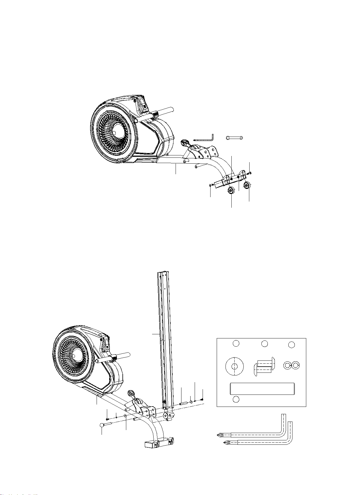
ASSEMBLY INSTRUCTION
2
3
4
3
4
2
1
1
34
38
37
41
34
37
38
35
45
φ8*φ
25mm
38
2X
M8*20mm
34
2X
37
φ
8mm
2X
41
φ
16*86mm 1X
6mm
www.puretecfitness.com
6
Step 1
Attach the two Roller Wheels (3) to the Main Frame (1). Secure each Roller Wheel (3) wi th
one Allen Bolt (4) and one Nylon Nut (2).
Step 2
Pull out the ball pin (35) from the main frame (1). Insert the slide rail (45) onto the U type
connect tube of m ain frame (1), faste n w ith on e ax le for slid e rai l (41) , t wo se ts o f allen b olt s
(34), spring washers (37) and flat washers (38).
Then insert the ball pin (35).
 Loading...