

Marcy GS 99 User Manual
NOTE:
Please read all instructions
carefully before using this
product
Table of Contents
Safety Notice
Hardware Pack
Assembly Instruction
Parts List
Resistance Chart
Warranty
Ordering Parts
Marcy Platinum
Corner Gym
GS 99
Model
GS 99
Retain This
Manual for
Reference
Jan-14-05
OWNER'S
MANUAL
IBL
Escalade International Limited
Pleasant Road, Penllegaer, Swansea. SA4 9GE
Tel: 00 44 1792 222 550 Fax 00 44 1792 895 781
www.escaladesports.co.uk
info@escaladesports.co.uk

TABLE OF CONTENTS
BEFORE YOU BEGIN...................................................................................... 1
IMPORTANT SAFETY PRECAUTIONS........................................................... 2
HARDWARE PACK……….....…....................................................................... 3
ASSEMBLY INSTRUCTIONS...............................................................…..........6
PARTS LIST…………………………………………………………….……….…… 25
RESISTANCE CHART………………………………………………………………. 26
WARRANTY.................................................................................................…. 27
ORDERING PARTS.......................................................................................... 27
CARE AND MAINTENANCE………………………………………………………. 28
BEFORE YOU BEGIN
Thank you for selecting the MARCY PLATINUM CORNER GYM by IMPEX FITNESS
PRODUCTS. For your safety and benefit, read this manual carefully before using the
machine. As the distributor, we are committed to provide you complete customer
satisfaction. If you have any questions, or find there are missing or damaged parts or you
require assistance assembling this product, we guarantee you complete satisfaction
through direct assistance. To avoid unnecessary delays, please call our customer service
department.
Monday to Friday 9am to 5pm.
Tel: 0044 (0) 1792 222562
E mail: customerservices@escaladesports.co.uk
Supplied by
Escalade International Ltd
Pleasant Road
Penllegaer
Swansea
SA4 9GE
Tel: 0044 (0) 1792 222550
Fax: 0044 (0) 1792 895781
www.escaladesports.co.uk
E mail: info@escaladesports.co.uk
1

IMPORTANT SAFETY PRECAUTIONS
This gym built for optimum safety. However, certain precautions apply whenever you operate
a piece of exercise equipment. Be sure to read the entire manual before you assemble or use
your gym. In particular, note the following safety precautions:
1. Keep children and pets away from the gym at all times. Do not leave children unattended in the
same room with the gym. The gym is not a toy and therefore parents and guardians should be
aware of the natural tendency for children to play, leading to situations and behaviour for which
the gym is not intended.
2. If children are allowed to use the gym their physical/mental development and above all,
temperament should be taken into account. Constant supervision is therefore needed.
3. If the user experiences dizziness, nausea, chest pain or any other abnormal symptoms, STOP the
workout at once. Consult a physician immediately. Injuries may occur due to incorrect or
excessive exercise.
4. Position the gym on a clear levelled surface which is clear of all obstacles as not to restrict
movement whilst exercising. DO NOT use the gym near water or outdoors.
5. Keep hands away from all moving parts
6. Always wear appropriate clothing when exercising. DO NOT wear robes or other clothing that
could become caught in the gym. Running or aerobic shoes are also required when using the
gym.
7. Use the gym only for its intended use as described in this manual. DO NOT use attachments not
recommended by the manufacturer.
8. Do not place any sharp objects around the gym.
9. Disabled persons should not use the machine without a qualified person or physician in
attendance.
10. Before using the gym to exercise, always do stretching exercises to properly warm up.
11. Never use the gym if it is not functioning properly.
12. This product is intended for H=Domestic use only.
WARNING: BEFORE BEGINNING ANY EXERCISE PROGRAM, CONSULT YOUR
PHYSICIAN. THIS IS ESPECIALLY IMPORTANT FOR INDIVIDUALS OVER THE AGE OF 35
OR PERSONS WITH PRE-EXISTING HEALTH PROBLEMS. READ ALL INSTRUCTIONS
BEFORE USING ANY FITNESS EQUIPMENT. MARCY ASSUMES NO RESPONSIBILITY FOR
PERSONAL INJURY OR PROPERTY DAMAGE SUSTAINED BY OR THROUGH THE USE OF
THIS PRODUCT.
SAVE THESE INSTRUCTIONS.
2

HARDWARE PACK

HARDWARE PACK
3

HARDWARE PACK
4
5
ASSEMBLY INSTRUCTION
Tools Required Assembling the Machine: Two Adjustable Wrenches and Allen Wrenches
NOTE: It is strongly recommended two or people assembling this machine to avoid
possible injury.
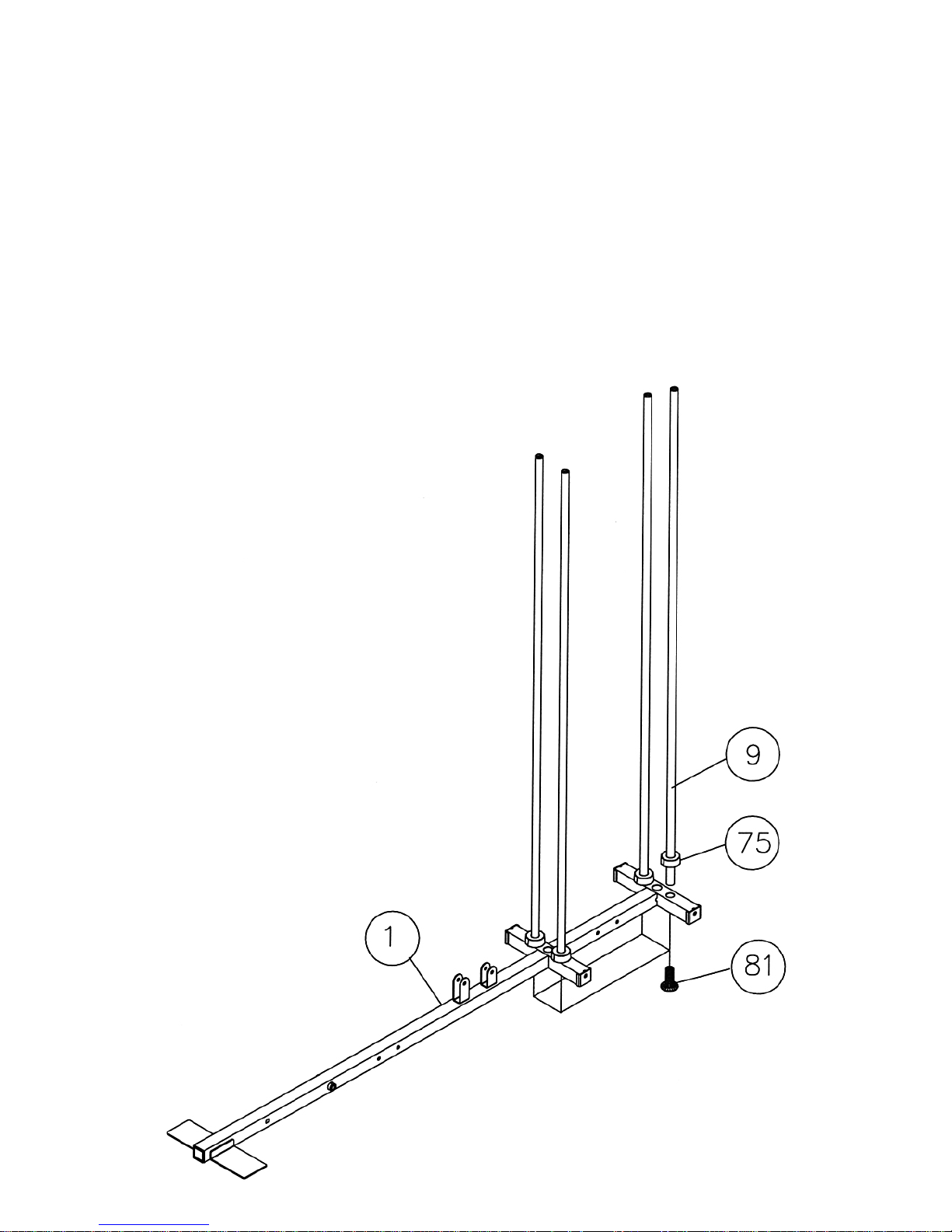
STEP 1 (See Diagram 1)
A.) Place the Right Base Frame (#1) on a flat surface. Make sure there is enough space around
to assemble the machine.
B.) Insert four Guide Rods (#9) into the holes on the Right Base Frame (#1). Secure each Guide
Rod to the Right Base Frame from the bottom with a M10 x 1” Allen Bolt (#81).
C.) Slide four Ø 2 ½” x 1” Rubber Bumpers (#75) onto the Guide Rods.
Diagram 1
6
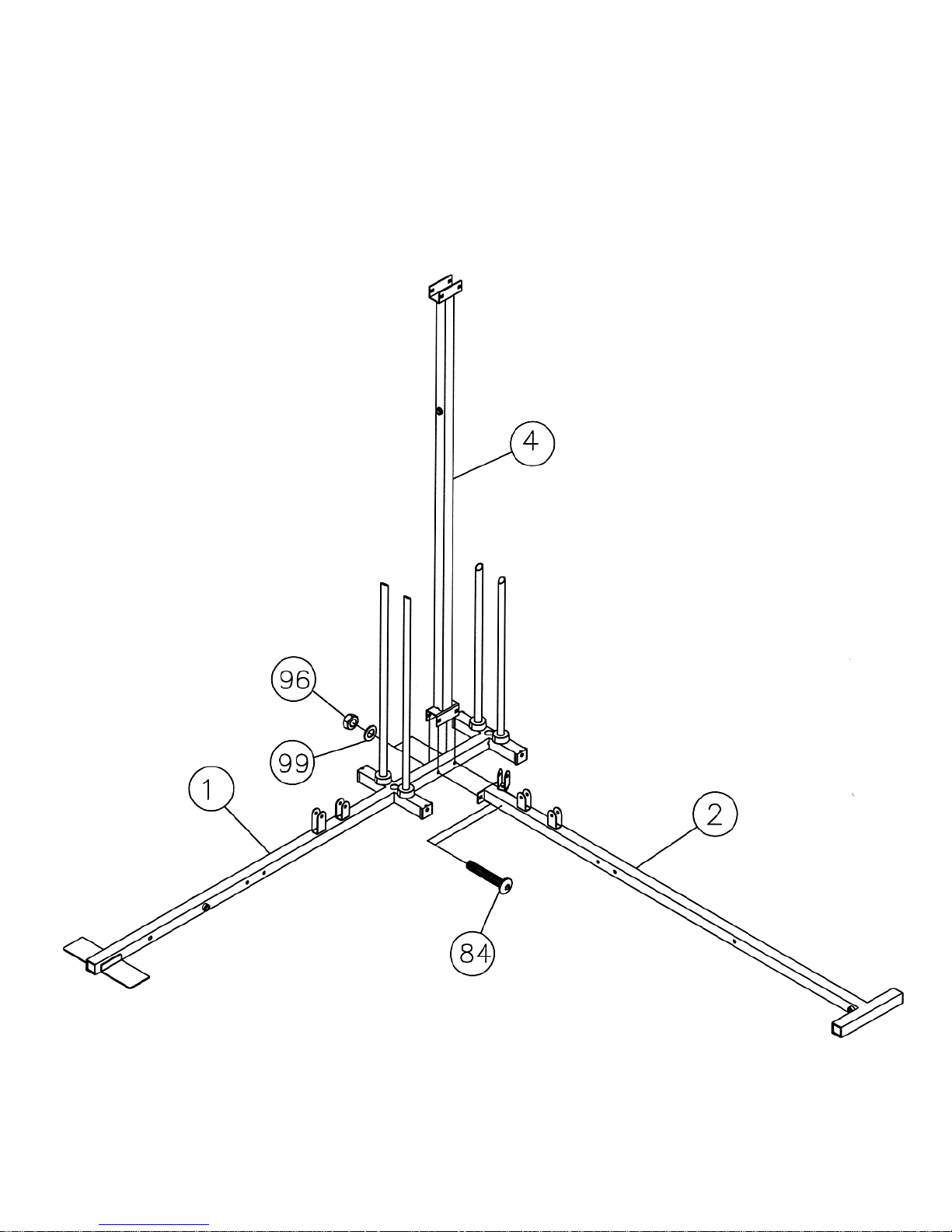
STEP 2 (See Diagram 2)
A.) Attach the Rear Vertical Frame (#4) to the Right Base Frame (#1). Attach the Left Base
Frame (#2) to the Rear Vertical Frame. Align the holes and secure them with two M10 x 2
¾” Carriage Bolts (#84), ∅ ¾” Washers (#99), and M10 Aircraft Nuts (#96).
B.) Do not tighten the Nuts and Bolts yet.
DIAGRAM 2
7
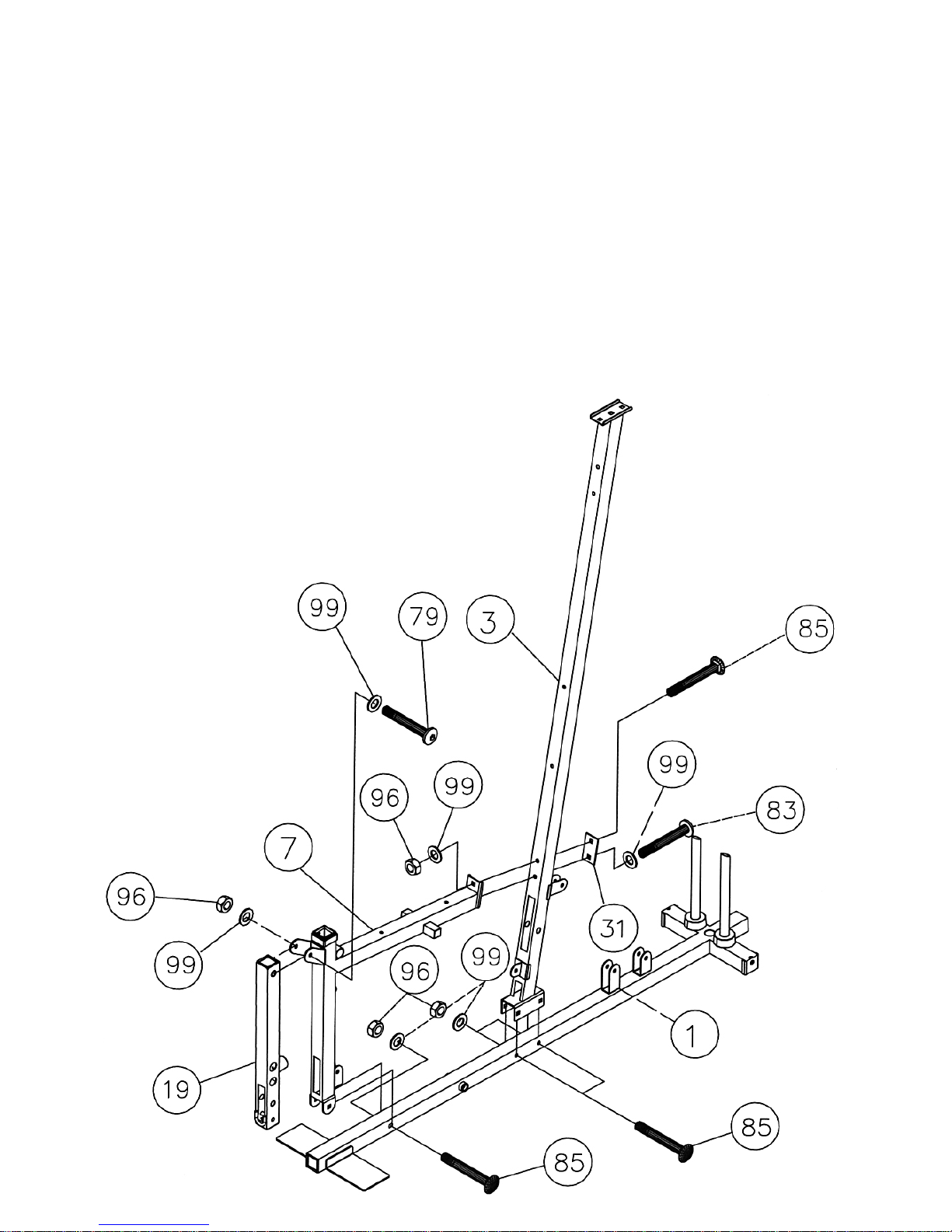
STEP 3 (See Diagram 3)
A.) Attach the Right Vertical Beam (#3) to the Right Base Frame (#1). Secure it with two
M10 x 2 ½” Carriage Bolts (#85), ∅¾” Washers (#99), and M10 Aircraft Nuts (#96). DO
not tighten the Nuts and Bolts yet.
B.) Attach the Right Seat Support (#7) to the Right Vertical Beam (#3). Secure it with one
M10 x 2 ½” Carriage Bolt (#85), one M10 x 2 3/8” Allen Bolt (#83), one 3 1/8” x 1 ¾”
Bracket (#31), two Ø ¾” Washers (#99), and one M10 Aircraft Nut (#96).
C.) Attach the Right Seat Support (#7) to the Right Base Frame (#1). Secure it with one
M10 x 2 ½” Carriage Bolt (#85), ∅ ¾” Washer (#99), and M10 Aircraft Nut (#96).
D.) Attach the Leg Developer (#19) to the bracket on the Right Seat Support (#7). Secure it
with one M10 x 2 7/8” Allen Bolt (#79), two Ø ¾” Washers (#99), and one M10 Aircraft
Nut (#96). Do not over tighten the Leg Developer, make sure it is able to swivel.
DIAGRAM 3
 Loading...