

Marcy CL603 User Manual
Cycle
Product Code: CL603
Escalade International Limited
Pleasant Road, Penllergaer, Swansea. SA4 9GE
Tel: 00 44 1792 222 550 Fax 00 44 1792 895 781
www.escaladesports.co.uk
info@escaladesports.co.uk
14-10-2009-1

Contents
Important Safety Information
Weight Limit Capacities
3
Hardware Parts List
Pre Assembly Check List
Assembly Instructions
User Guide
Computer Instructions
Exercise Instructions
Fault Finding Chart
Exploded Diagram
Parts List
Additional Information
Care Maintenance
Limited Warranty
4
5
6 – 9
10 – 11
12
13
14
15
16
17
18
Supplied by
Escalade International Ltd
Pleasant Road
Penllergaer
Swansea
SA4 9GE
Tel: 00 44 1792 222550
Fax: 00 44 1792 895781
www.escaladesports.co.uk
E mail: info@escaladesports.co.uk
2

IMPORTANT SAFETY INFORMATION
READ ALL INSTRUCTIONS BEFORE USE
THIS OWNER’S MANUAL CONTAINS ASSEMBLY, OPERATION, MAINTENANCE
1. This cycle is intended for class H (H=Domestic) use only. It is not designed for commercial use.
2. This cycle has been tested to BS EN 957 Parts 1:2005 and Part 5:1996.
3. Read the OWNER’S OPERATION MANUAL and all accompanying information and follow it
4. Keep children and pets away from the Cycle at all times. Do not leave children unattended in the
AND SAFETY INFORMATION. IN THE INTEREST OF SAFETY, PLEASE MAKE
CERTAIN THAT YOU READ AND UNDERSTAND ALL THE INFORMATION BELOW.
carefully before using your cycle.
same room with the Cycle. The Cycle is not a toy and therefore parents and guardians should
be aware of the natural tendency for children to play, leading to situations and behaviour for
which the Cycle is not intended.
5. If children are allowed to use the Cycle their physical/mental development and above all,
temperament should be taken into account. Constant supervision is therefore needed.
6. Position the Cycle on a clear levelled surface which is clear of all obstacles as not to restrict
movement whilst exercising. DO NOT use the Cycle near water or outdoors.
7. Exercise equipment has moving parts. In the interest of safety, keep others, especially children,
at a safe distance while exercising.
8. Never hold your breath while exercising. Breathing should remain at a normal rate in conjunction
with the level of exercise being performed.
9. Rest adequately between workouts. Muscle tone develops during these rest periods. Beginners
should work out twice a week and increase gradually to 4 to 5 times per week.
10. Remove all jewellery, including rings, chains and pins before commencing exercise.
11. Always wear suitable clothing and footwear during exercise. Do not wear loose fitting clothing
that could become entangled with the moving parts of your exercise machine.
IMPORTANT!!! THE MAXIMUM RECOMMENDED WEIGHT CAPACITY FOR YOUR CYCLE IS
120KGS.
3
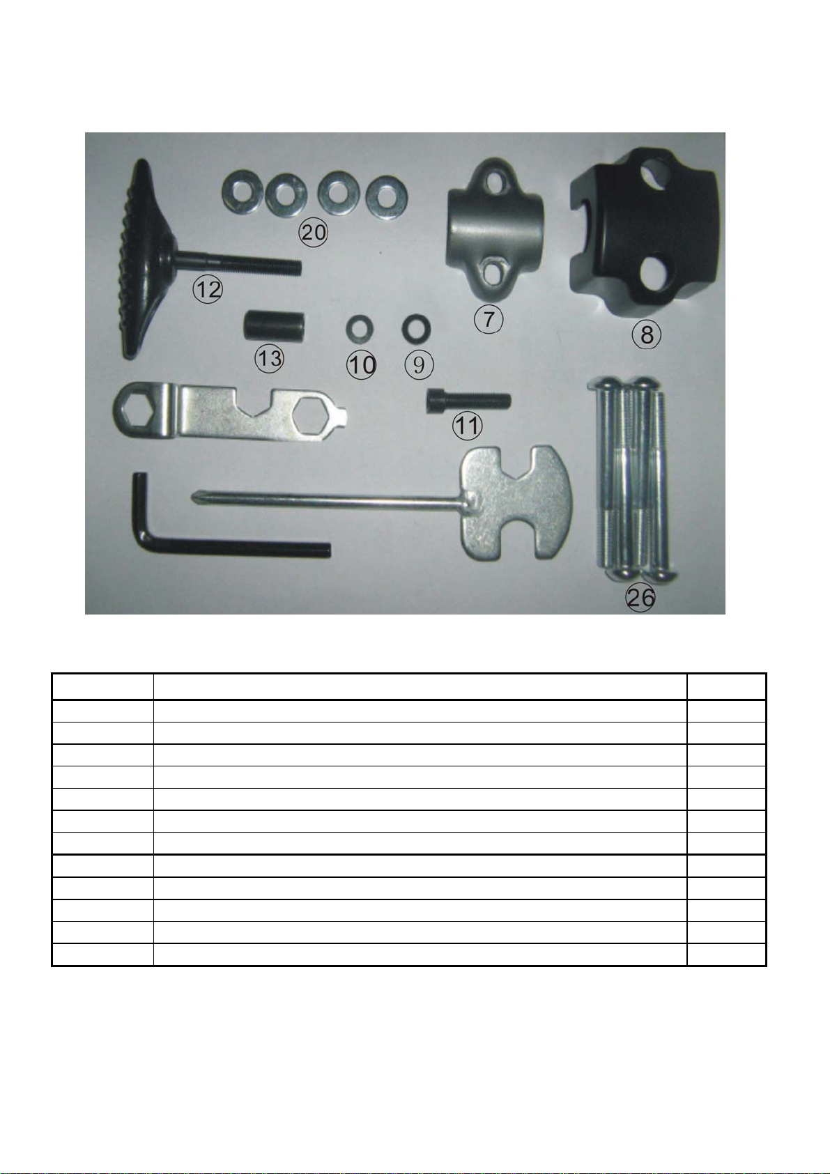
HARDWARE PARTS LIST
Part No. Description Q’ty
7
8
9 Flat washer ф7*ф12*1T 1
10 Spring washer ф7*ф13*2T 1
11 Allen Head Bolt M7*30 1
12
13
20 Flat washer ф8*ф19*2T 4
26 Allen Head Bolt M8*72 4
Allen key S6 1
Wrench 13/15 1
N-shape wrench 13/14/15 1
Metal cover for handlebar
Plastic cover for handlebar ABS
T knob M7x55L
Steel bush ф7*ф12*25
1
1
1
1
Above described parts are all the parts you need to assemble this machine. Before you
start to assemble, please check the hardware packing to make sure they are included.
Please note that some items of hardware may already be pre assembled onto your cycle.
4
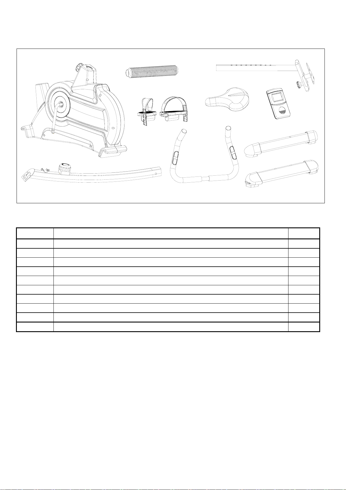
PRE-ASSEMBLY CHECK LIST
NO.45
NO.25
NO.36
NO.32
NO.01
NO.47
NO.17
Part No. Description Qty
01
06
17
23
25
27
32
36 Seat Post 1
45 Bellows 1
47 Main Frame 1
Computer
Handle bar
Handle Bar Post
Rear Stabilizer
Pedal(R/L)
Front Stabilizer
Saddle
NO.06
NO.27
NO.23
1
1
1
1
2
1
1
5

ASSEMBLY INSTRUCTIONS
STEP 1
Attach the Front Stabilizer (27) to the Main Frame (47) using 2 Allen Head Bolts (26) and 2 Flat
Washers (20).
Attach the Rear Stabilizer (23) to the Main Frame (47) using 2 Allen Head Bolts (26) and 2 Flat
Washers (20).
47
27
20
26
STEP 2
Ensure the Tension Control Knob is set to number 1. Slide the Handlebar Post cover (24) onto
the end of the Handlebar Post. Connect the Upper Tension Control Cable (16) to the Lower Tension
Control Cable (31). Please see the next page for a detailed description of the assembly.
Connect the Upper Sensor Wire (14) to the Lower Sensor Wire (30). Assemble the Handlebar Post
onto the Main Base and secure using 4 Allan Head Bolts (19) and 2 Flat Washers (18) and 2
Curved Washers (18).
23
18
19
16
20
14
24
6
 Loading...