

Marcy 1201U User Manual

www.puretecfitness.com
1
1201U
UPRIGHT BIKE
USER MANUAL
Distributed By:
Pure-Tec Limited
www.puretecfitness.com

www.puretecfitness.com
2
CONTENTS
Important Saf ety Information
Weight Limit Capacities
Hardware Parts Lis t
Pre Assembly Check List
Assembly Instructions
Computer Instruct ions
Exercise Instructions
Exploded Diagram
Parts List
Additional Information
Warranty Information
3
4
5
6 - 9
10-11
12-13
14
15-16
17
18
BEFORE YOU BEGIN
Thank you for selecting the MARCY 1201U Upright Bike. For your
safety and benefit, read this manual carefully before using the equipment.
As the official distributor for Marcy, we are committed to providing
complete customer satisfaction. If you have any questions, or find there are
missing or damaged parts, we guarantee you complete satisfaction
through direct assistance. To avoid unnecessary delays, please contact
our Customer Solutions Department, Monday to Friday 8am – 5pm GMT.
Pure-Tec Limited
www.puretecfitness.com
Tel: +44 (0) 1482 212098
Email: service@puretecfitness.com
Monday - Friday 0800 - 1700GMT

www.puretecfitness.com
3
IMPORTANT SAFETY INFORMATION
READ ALL INSTRUCTIONS BEFORE USING
1. This Bike is intended for class H (H=Domestic) use only. It is not designed for
commercial use.
2. This machine has been t es ted to EN 957.
3. Read the OWNER’S OPERATION MANUAL and all accompanying literature and follow it
carefully befor e using your Bike.
4. Keep children and pets away from the Bike at all times. Do not leave children unattended
in the same room with the Bike. The Bike is not a toy and therefore parents and
guardians should be aware of the natural tendency for children to play, leading to
situations and behaviour for w hic h the Bike is not intended.
5. If chil dren are a llowe d to use th e Bik e their phys ical/ mental develop ment and abov e al l,
temperament s hould be taken into account. Constant supervision is therefore needed.
6. Position the Bike on a clear levelled surface which is clear of all obstacles as not to
restrict mov em ent whilst exercising. DO NOT use the Bike near water or outdoors.
7. Exercise equip ment has moving parts. In the interes t of safety, k eep others , especially
children, at a safe distance while exercising.
8. Nev er hold your breath w hile exercising. Breathing should remain at a normal rate in
conjunction with the level of exerc ise being performed.
9. Rest adequately between workouts. Muscle tone develops during these rest periods.
Beginners should work out twice a week and increase gradually to 4 to 5 times per
week.
10. Remove all je wellery, including rings, chains and pins befor e c ommencing exercise.
11. A lways wear suitable clot hing and footwear durin g exercise. Do not wear loose fitting
clothing that c ould become enta ngled with the moving parts of your exer cise machine.
IMPORTANT!! ! THE MAXIMUM RECOMMENDED WEIGHT CAPACITY FOR YOUR
BIKE IS 110KGS.
THIS OWNER’S MANUAL CONTAINS ASSEMBLY, OPERATION, MAINTENANCE AND
SAFETY INFORMATION. IN THE INTEREST OF SAFETY, PLEASE MAKE CERTAIN THAT
YOU READ AND UNDERSTAND ALL THE INFORMATION BELOW.
www.puretecfitness.com
4
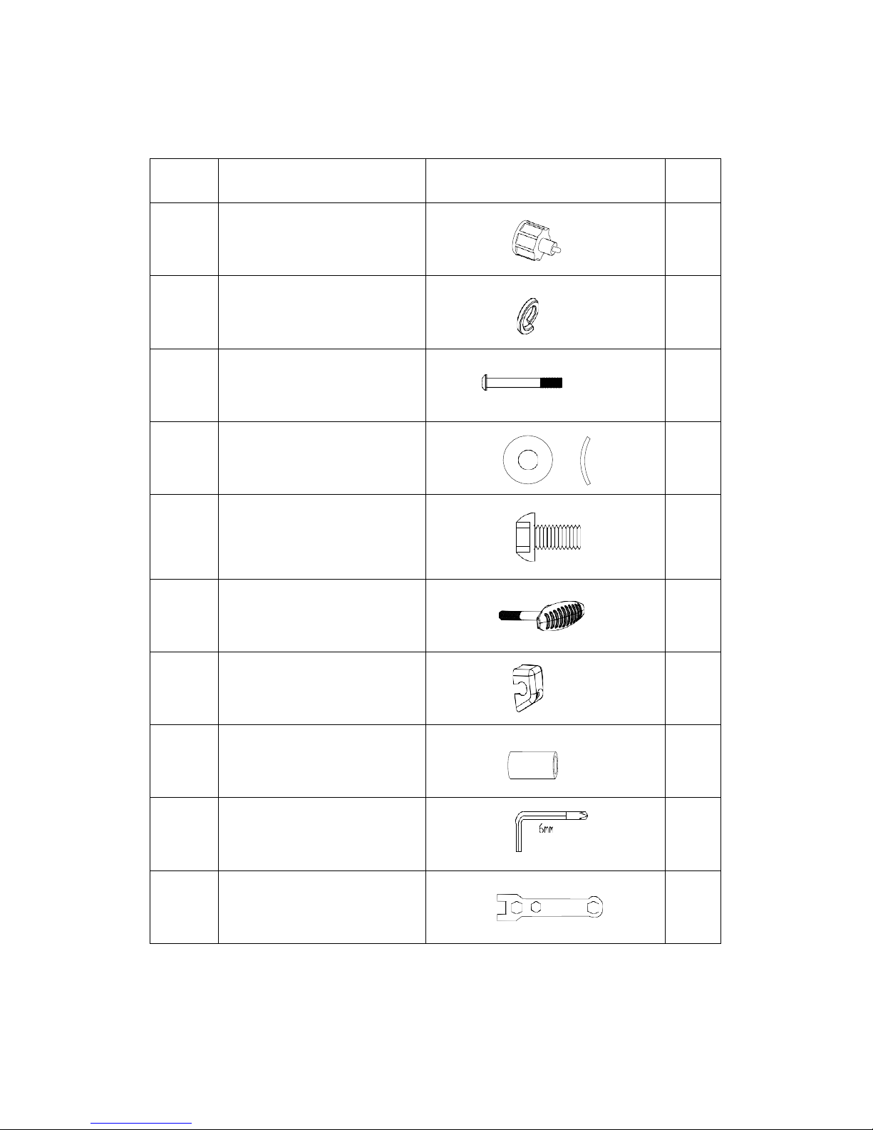
HARDWARE PACKING LIST
NO. DESCRIPTION DRAWING QTY
11
Quick Release L oc k Knob
1
13
Spring Washer
4
15
Allen Bolt M8*7 5
4
16
Curved Washer Φ20* Φ8
8
18
Allen Bolt M8*1 6
4
21
T-shaped Lock K nob
1
37
Decorative Cover
1
19
Bushing
1
Allen key L6
1
Box Wrench
1
www.puretecfitness.com
5
4
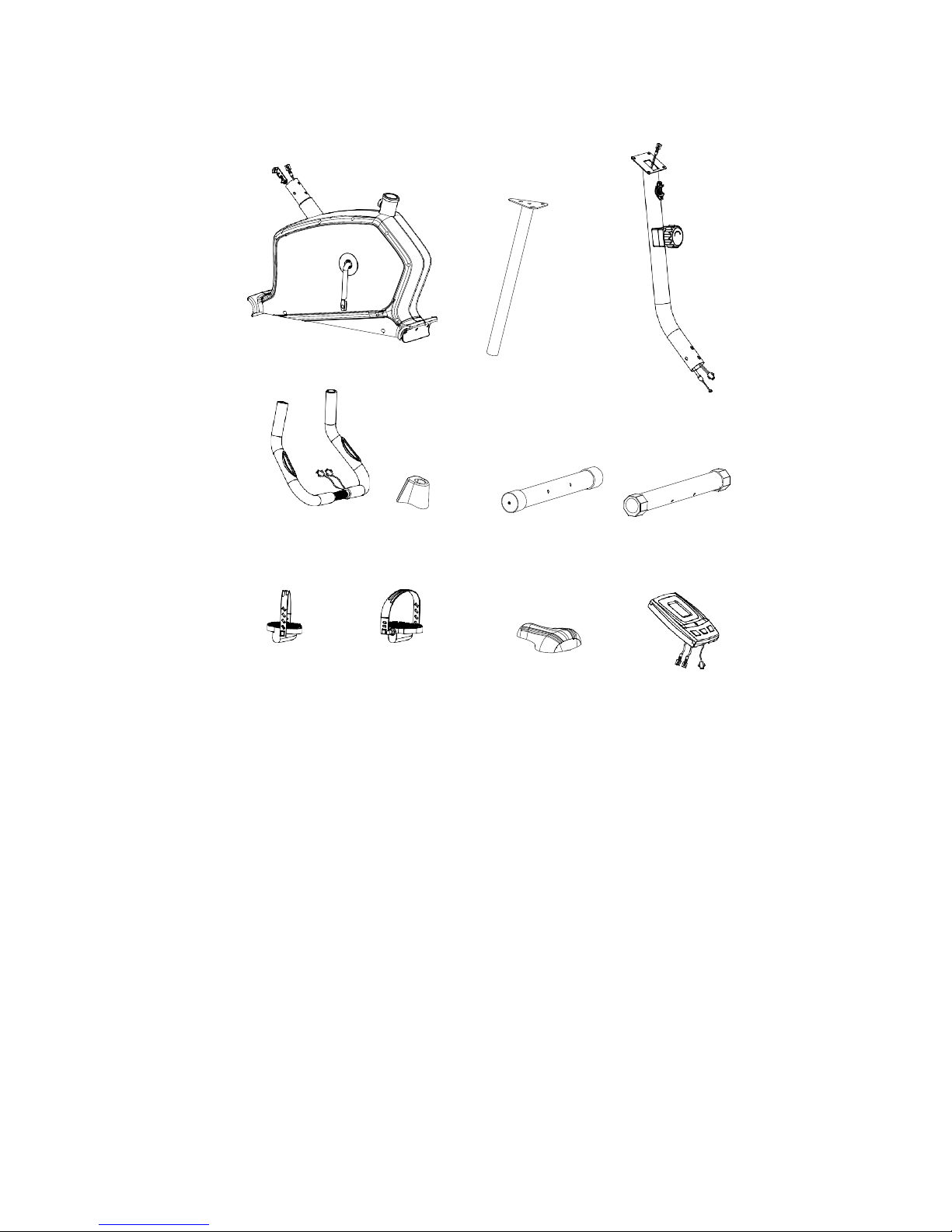
PRE-ASSEMBLY CHECK LIST
1
7
5
17 2
3
9 10 8 6
PART NO.
DESCRIPTION
Q’TY
1 Main frame 1
4 Front support 1
7 Seat support 1
6 Meter 1
9/10 Pedal ( L/R ) 1/1
17 Front support cover 1
8 Seat 1
5 Handlebar 1
2 Front stabili zer 1
3
Rear stabilizer
1
www.puretecfitness.com
6
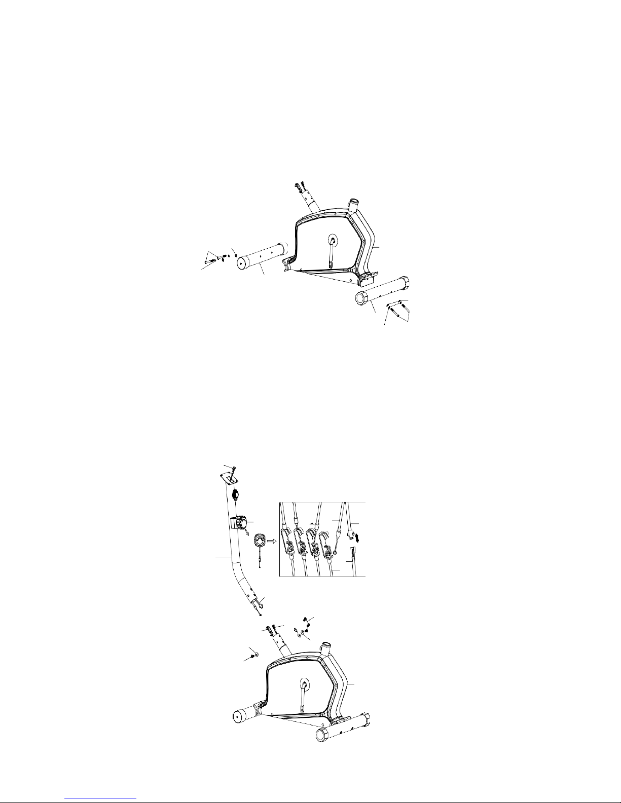
STEP 1
ASSEMBLY INST RUCTION
Attach the fr ont stabilizer (2) to t he main frame (1), Sec ur e using two curved washer (16),
two Spring Washer (13) and Allen Bolt (15).
Attach the rear s tabilizer (3) to t he m ain frame (1), Sec ur e us ing two curved washer (16),
two Spring Washer (13) and Allen Bolt (15).
STEP 2
15
16
13
2
1
16
3
13
15
Connect the middle computer wire ( 33) with lower computer wire (34).
Turn the tens ion knob (60) to level 8 and connect the t ens i on knob w/upper tension cable
(60) to the extension with the low er tension cable (61).
Insert the front pos t (04) into the main frame (1) and secure using four al len screws (18)
and four curved washers (16).
33
60
60
33
4
34
61
33
18
61
34
16
16
18
1
 Loading...