

Marcy 1201R User Manual
1
1201R
RECUMBENT BIKE
USER MANUAL
Distributed By:
Pure-Tec Limited
www.puretecfitness.com
www.puretecfitness.com

www.puretecfitness.com
2
CONTENTS
Important Safety
Information Weight Limit Capacities
Hardware Parts List
Pre Assembly Check List
Assembly Instructions
Computer Instructions
Exercise Instructions
Exploded Diagram
Parts List
Additional Information
Warranty Inform
ation
3
4
5
6- 9
10-11
12-13
14-15
16-17
18
BEFORE YOU BEGIN
Thank you for selecting the MARCY 1201R Recumbent Bike. For your
safety and benefit, read this manual carefull y before using the equipment.
As the official distributor for Marcy, we are committed to providing
complete customer satisfaction. If you have any questions, or find there are
missing or damaged parts, we guarantee you complete satisfaction
through direct assistance. To avoid unnecessary delays, please contact
our Customer Solutions Department, Monday to Friday 8am – 5pm GMT.
Pure-Tec Limited
www.puretecfitness.com
Tel:
+44 (0) 1482 212098
Email: service@puretecfitness.com
Monday - Friday 0800 - 1700GMT
19

www.puretecfitness.com
3
IMPORTANT SAFETY INFORMATION
READ ALL INSTRUCTIONS BEFORE USING
1.
This Recumbent Bike is intended for class H (H=Domestic) use only. It is not
designed for commercial use.
2.
This machine has been tested to EN 957.
3.
Read the OWNER’S OPERATION MANUAL and all accompanying literature and follow it
carefully before using your Recumbent Bike.
4.
Keep children and pets away from the Recumbent Bike at all times. Do not leave children
unattended in the same room with the Recumbent Bike. The Recumbent Bike is not
a toy and therefore parents and guardians should be aware of the natural tendency
for children to play, leading to situations and behaviour for which the Bike is not
intended.
5.
If children are allowed to use the Recumbent Bike their physical/mental development
and above all, temperament should be taken into account. Constant supervision is
therefore needed.
6.
Position the Recumbent Bike on a clear levelled surface which is clear of all
obstacles as not to restrict movement whilst exercising. DO NOT use the Recumbent
Bike near water or outdoors.
7.
Exercise equipment has moving parts. In the interest of safety, keep others, especially
children, at a safe distance while exercising.
8.
Never hold your breath while exercising. Breathing should remain at a normal rate in
conjunction with the level of exercise being performed.
9.
Rest adequately between workouts. Muscle tone develops during these rest periods.
Beginners should work out twice a week and increase gradually to 4 to 5 times per
week.
10.
Remove all jewellery, including rings, chains and pins before commencing exercise.
11.
Always wear suitable clothing and footwear during exercise. Do not wear loose fitting
clothing that could become entangled with the moving parts of your exercise machine.
IMPORTANT!! ! THE MAXIMUM RECOMMENDED WEIGHT CAPACITY FO R Y O UR
BIKE IS 110KGS.
THIS OWNER’S MANUAL CONTAINS ASSEMBLY, OPERATION, MAINTENANCE AND
SAFETY INFORMATION. IN THE INTEREST OF SAFETY, PLEASE MAKE CERTAIN THAT
YOU READ AND UNDERSTAND ALL THE INFORMATION BELOW.

www.puretecfitness.com
4
HARDWARE PACKING LIST
No. Description Identifier Q’ty
2
Allen screw M8*75
2
4
Spring washer Φ8
2
5
Curved washer Φ8*Φ20*1.5 12
21 Allen screw M8*16 30
23 Carriage bolt M 10*75
2
24 Curved washer Φ10*Φ22*1.5
2
28 Carriage bolt M 8*40
2
29 Domed nut M8
2
31
Domed nut M10
2
38 Flat washer Φ17*Φ8.5
6
39 Leveling pad 1
42
Quick release knob
1
Crossing Wren ch 1
Allen KeyL6 1
www.puretecfitness.com
5
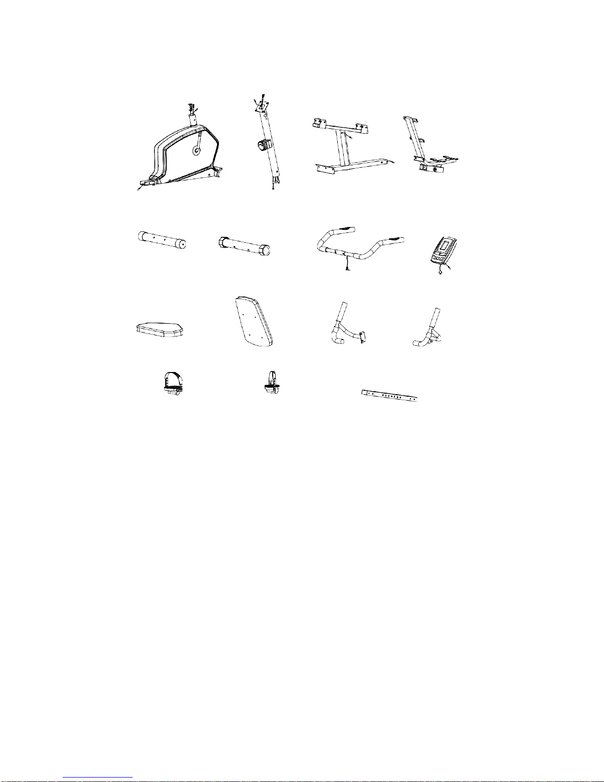
PRE-ASSEMBLY CHECK LIST
1 9 40 43
3
6
13
10
44
12
11
37 41
PART NO.
DESCRIPTION
Q’TY
1
Main frame
1
3
Front stabili zer
1
6
Rear stabili zer
1
9
Front post
1
10 Computer 1/1
11 Stat ionary handlebar R
1
12 Stationary handlebar L
1
13 Rear handlebar
1
36/37 Right / Left peda l
1
40 Support tube 1/1
41 Sliding tube
1
43 Seat support br ac ket
1
44 Back cushion
1
45
Seat cushion 1
www.puretecfitness.com
6
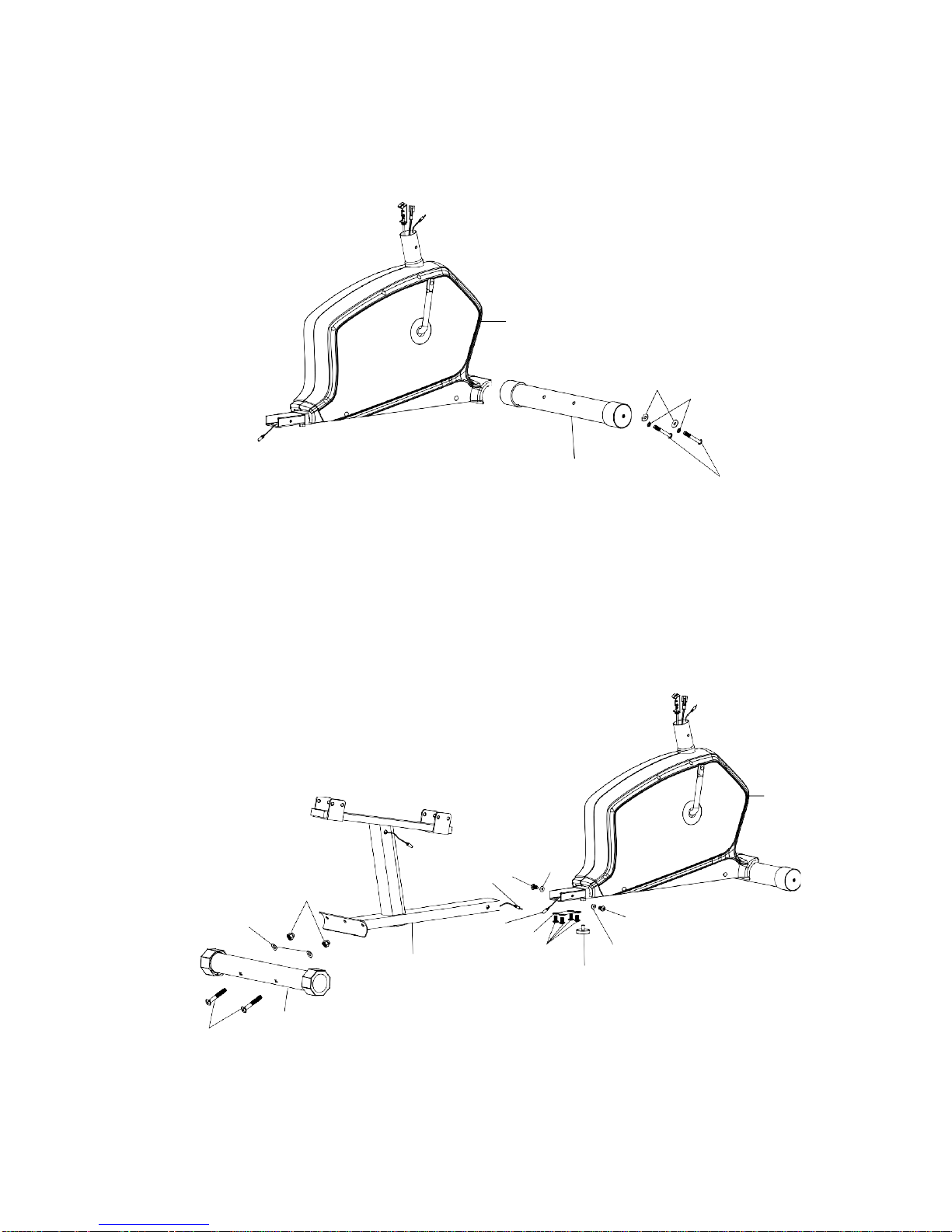
STEP 1
ASSEMBLY INST RUCTION
Attach the fr ont stabilizer (3) to the main frame (1), securing with two al len screws (2), two spring
washers (4) and two curved washers (5) .
1
5
4
3
2
STEP 2
Connect mi ddle extension hand pulse wire (47) with rear extension hand pulse wire (46) . Attach
support tube (40) to mai n frame (1), and tighten with 6 sets of allen screw (21) and flat w asher (38).
Attach the leveling pad (39) to the bottom of main frame (1).
Attach rear st abili zer (6) to the support tube (40) and tighten with 2 sets of carri age bolt (23), curved
washer (24) and domed nut (31).
Tip: Avoid pinching the Extension Wires
1
31
24
23
6
46
21
38
47
38
21
40
21
39
38
 Loading...